Sunday, 8 April 2018

'Learn to be a Driver' Courses at Birmingham Railway Museum

In the post Birmingham Railway Museum, Tyseley, I talked about some of my experiences working as a volunteer at Birmingham Railway Musuem. In an attempt to boost the Museum's income, 'Learn to be a Driver' Courses were introduced whilst I was there, allowing novices to spend a day learning a little about railways and actually driving steam locomotives. These courses were divided into a number of sessions and the format was immediately successful:-
1. Mandatory safety briefing.
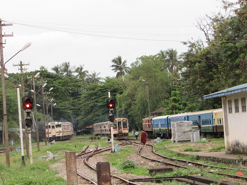
2. The Shunter (person on the ground marshalling vehicles).
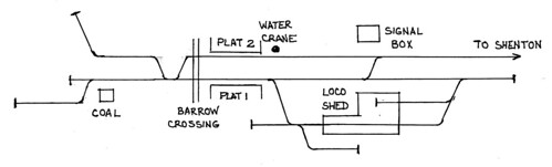
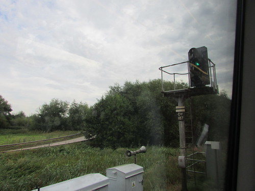
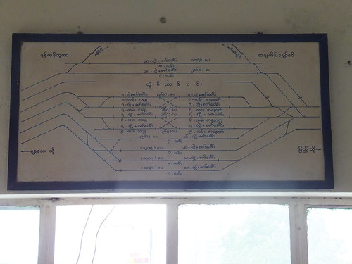
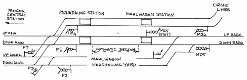
3. Signalling (using the Museum's working signal box).
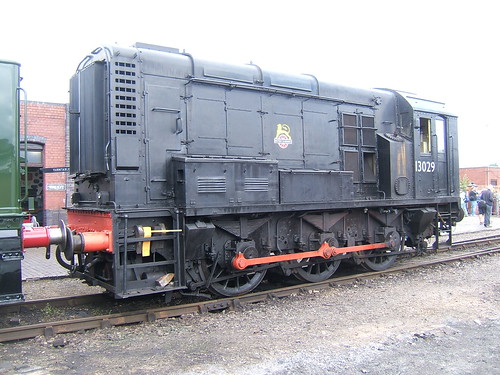
4. Locomotive engineering (using locomotives under repair/restoration).
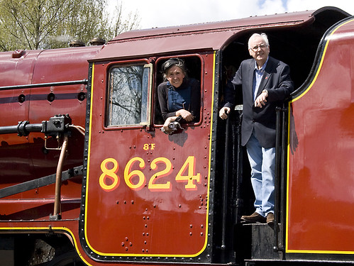
5. Driving and firing a small tank engine.
6. Driving and firing a well-known tender engine.

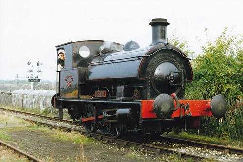
'Henry' often served as the small tank engine.


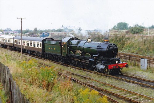
Initially, 5080 'Defiant' was the tender engine (here shown on a passenger train on a Gala Day on 9-Oct-1994).

The trainees were divided into groups of 3 on the footplate, with an Instructor Driver (who in addition to supervising the trainees was responsible for firing/boiler management). For the non-footplate sessions, two footplate groups were usually combined so museum volunteers gave talks to groups of 6 or more trainees and, if 'friends and family' chose to join these sessions, parties of 12 or more were common!

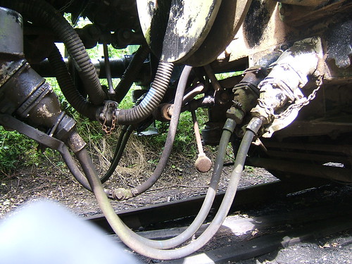
The Shunter's session looked at static wagons, examined manual and vacuum braking systems and demonstrated the use of the Shunting Pole and Brake Stick. Some trainees were keen to try for themselves. Some of the things we explained on these sessions are described in this blog in posts titled 'The Role of the Shunter', starting here.

In the signal box, apart from looking at the mechanical and electrical equipment in the locking room of the signal box, the operating floor gave opportunities for trainees to work the lever frame.

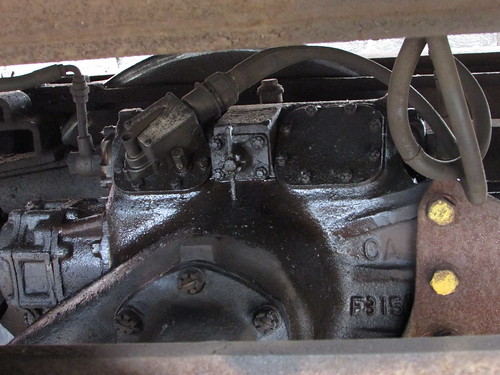
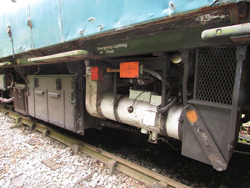
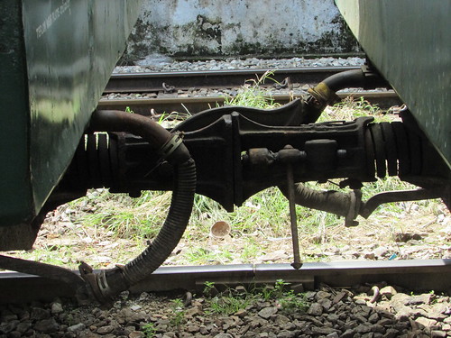
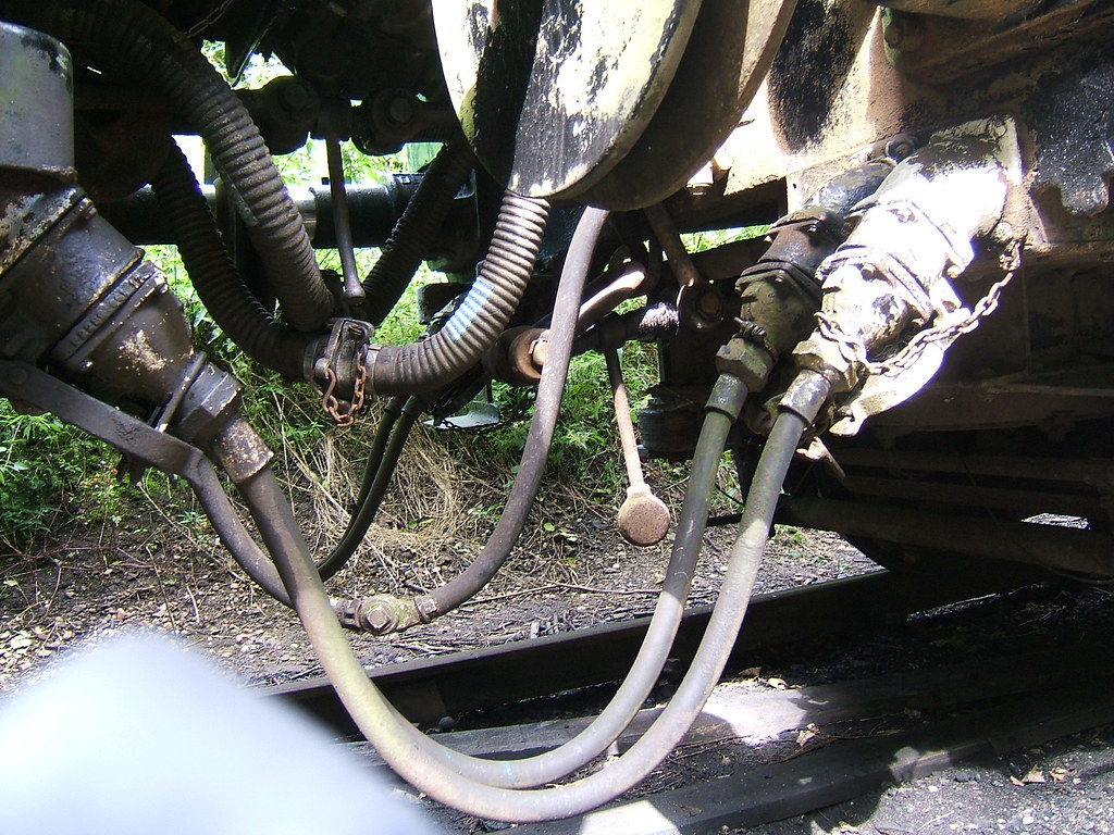
The Locomotive Engineering session conducted in the workshops and outside around the yard with various dismantled locomotives allowed close-up views of different parts of locomotives, including wheelsets, frames, cylinders, motion and boilers. The talks were a very simplified version of the syllabus being covered in Mutual Improvement Classes (MIC) for volunteers at Birmingham Railway Museum being run at the same time, in which I was involved. The background to MIC courses is described in the post here and there's an index of posts in this blog which have the kind of technical content covered in MIC Classes here.

Although the driving sessions were what people had come for, I was surprised and gratified at how much serious interest was shown in the shunting, signalling and locomotive engineering sessions, by both trainees and friends and family'.

Other locomotives were made available to drive from time to time, so the 'small tank engine' role was fulfilled variously by Avonside 'Cadbury No. 1', Bagnall 'Victor' and at least two Tyseley Panniers. A constellation of tender engines included:-
7029 'Clun Castle'
6024 'King Edward I
4920 'Dumbleton Hall'
45593 'Kolhapur'
6203 'Princess Margaret Rose'
34027 'Taw Valley'
35005 'Canadian Pacific'
4498 'Nigel Gresley'
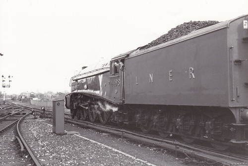
Birmingham Railway Museum: Jan instructing on streamlined A4 4498 'Nigel Gresley'.

Remarkably the iconic Gresley A3 4472 'Flying Scotsman' also made a number of visits offering driving experiences - there's a post about 'Flying Scotsman' at Birmingham Railway Museum here.

Related Posts on this Website

Birmingham Railway Museum, Tyseley.
'Flying Scotsman' at Birmingham Railway Museum.
Index of MIC-related posts.

My Pictures

Where necessary, clicking on an image above will display an 'uncropped' view or, alternately, pictures may be selected, viewed or downloaded, in various sizes, from the album listed:-

Birmingham Railway Museum.
Tyseley 100.


Diesel Multiple Unit, Easter 2018

The Battlefield operated steam trains with 'Cumbria' over the 2018 Easter Holiday but, starting on Tuesday 3rd April, a Diesel Multiple Unit (DMU) service took over. On Tuesday, Ritchie ran a 2-car DMU comprising half of the 2-car set (the other half is awaiting 'shopping') connected to the single unit DMU 55005. The following day, I was to operate the same formation.

Events of Wednesday, 4th April

I performed the daily exam and check of levels then attempted ground start of the four 150 horse power 'flat six' bus engines. This is carried out on each underframe-mounted engine control panel in turn, holding the manual throttle in 'full rack' position whilst pressing the electric start button until the engine is firing.


'Flat Six' 150 h.p. bus engine. The red-painted box is the battery charging point. The orange-painted box top right is the engine control panel.

The manual throttle is then progressively eased back to the 'idling' position. To avoid the engine cutting-out, this may take a few seconds. If the engine does stop, a fresh attempt at 'cranking' can only be made after a short delay. The two engines on the single unit 'Bubble Car' started fine but neither engine on the other vehicle would crank. In each case, the starter solenoid came in with a reassuring 'clunk' but there seemed very little movement of the engine. Since both engines were similarly affected, I diagnosed discharged battery. Each vehicle has its own heavy-duty lead-acid 24 volt battery but the heavy current demand when starting each engine means that a good battery in an adjacent vehicle cannot be used to 'jump start' a failed car. The service could have been performed with both cars if one of the two failed engines could have been started, in which case the final drive on the failed engine would have been isolated but this is not recommended with both engines on a power car 'out'.


The vertical bar is the Final Drive Isolating Switch in the 'engaged' position. When horizontal, the drive is 'isolated'.

There seemed two options: put the discharged battery on mains charge or 'ditch' the problem car, performing the service with just the one-coach 'Bubble Car'. Depending on the charge remaining in the battery, it was possible that an hour's charging would allow engine start but, adding the time to connect up and remove the mains charger, that would have put the start of service seriously late. So, after a brief discussion, it was agreed to use only the single unit, which was the vehicle at the southern end of the set. So the 'Bubble Car' had to propel the failed vehicle out of the way at the north end of the station, 'tie it down' and then split the two vehicles. I'd hoped that we might be able to recharge the battery during the day from one of the power sockets provided on the platform face but this did not prove possible.


Shackerstone track diagram sketch. North is to the left on this sketch.

In the post Santa Specials at the Battlefield Line 2017 I commented "The rather cramped track layout at Shackerstone requires careful choreography to manage two trains" but, on the morning of 4th April, with various items of freight and passenger rolling stock awaiting shunting operations to be completed, our options were very limited and we decided to leave the failed vehicle in the north end of platform 1.

Splitting DMU vehicles, interconnected by a screw shackle, air hoses, duplicated vacuum hoses and various electrical jumpers is not a trivial task and I was grateful to Adrian for relieving me of this job.

Click for larger image
Details of the interconnections between vehicles.


The picture above shows the arrangement and, of course, there's not much room to work. Referring to the picture above, starting nearest the camera, you have:-
1. Jumper cable on left vehicle ('black') attached to multipole connector on right vehicle.
2. Jumper cable on left vehicle ('white')attached to multipole connector on right vehicle.
3. Control air hoses, joined with 'palm' coupling.
4. Vacuum brake train pipe corrugated hoses, joined with standard vacuum connection ('red').
5. Vacuum brake 'quick release' corrugated hoses, joined with 'reversed' vacuum connection ('blue').
6. Standard screw coupling on left vehicle, attached to right vehicle and tightened.
7. Standard screw coupling on right vehicle, not used and suspended from hook on underframe.
8. Jumper cable on right vehicle ('white') attached to multipole connector on left vehicle.
9. Jumper cable on right vehicle ('black') attached to multipole connector on left vehicle.
10. The round buffer heads nearer the camera are visible at the top of the picture.
Jumper cables not in use are 'stowed' in a receptacle adjacent to the jumper cable. 'Palm' couplings are standard on railways for air lines and they are mated and de-mated with an action similar to rubbing your hands together, hence the name. To avoid confusion between the two vacuum brake hoses, the fittings on the 'quick release' hoses are the mirror image of the standard coupling. On DMU, palm coupling fittings are often painted white, vacuum hose fittings red and 'quick release' hose fittings blue.

Finally, the Guard placed an unlit oil tail lamp on the lamp bracket at the south end of the failed vehicle as a warning to the driver of an approaching train during the day (me!). By the time all this was accomplished, we were around ten minutes late and our passengers had already boarded the 'Bubble Car' so the Guard gave the 'Right Away' (two buzzes on the Guard/Driver annunciator) which I acknowledged.


DMU: Guard's buzzer pushbutton and Buzzer Code.

We started our booked 'diagram' of four round trips to Shenton as the sky darkened and the weather deteriorated to heavy rain. I started the electrically-controlled diesel-fuel powered warm air heater and, after a while, the passenger compartment was quite cosy. The driver's cabs weren't bad, either.


Left: Battery Box, Right: Underfloor warm air heater.

Ritchie had installed new windscreen wiper blades as well but my initial optimism was tempered by the rather erratic wiper motion produced by the air motors. However, we completed our workings without incident and, by the time we'd finished, it had even stopped raining. It remained to retrieve the failed vehicle from the north end of Platform 1, stable on the DMU siding and put the battery on charge overnight ready for the next day. I closed up to the failed vehicle and Dave attached the screw shackle. I decided to leave all the jumpers and hoses disconnected, in case only the single unit was used the following day (we were not expecting large numbers of passengers).

However, when I'd shunted the failed vehicle that morning, I'd had the benefit of a working vacuum brake because it was still 'piped' to the Bubble Car so, once the vacuum was 'destroyed' the vacuum cylinders on each bogie applied the brakes. Although vacuum brakes will eventually 'leak off', in a well-maintained cylinder the brakes can remain applied for days before enough air leaks past the piston seal in the cylinder to reduce the partial vacuum above the piston and allow the brake blocks to release. Reliance is never placed on how good the leakage performance of a brake cylinder might be and handbrakes are always applied to an isolated vehicle. I had the choice of either re-connecting the brake hoses to the vehicle so that vacuum could be re-created below the piston or ensuring brake release by deliberately admitting air above the brake piston to destroy the persistent vacuum. This is done by opening a release valve associated with each brake cylinder. Because of the inaccessibility of these valves, there is normally a stout cord leading from the valve to framing on each side of the vehicle. Tugging on the cord opens the valve and, after a few seconds, the brake piston should have descended fully, releasing the brake.

In an ordinary bogie coach, the brake cylinders are normally mounted on the coach underframe, adjacent to each bogie. But in a DMU the underframe space is already filled with equipment - engines, transmission, compressors, exhauster - so the vacuum brake cylinders are mounted on the bogie frame itself, with the release cord on the outer end of the bogie. Manually releasing vacuum brakes on any type of vehicle is always called "pulling the strings".

With the brakes released, the Bubble Car then dragged the failed driving motor coach into the siding, allowing the 'big shunt' to be completed by a diesel shunter at some stage. The engines were shut-down, handbrakes applied to both vehicles and the battery charger was connected to the battery charging socket on the failed vehicle in the hope of restoring the battery overnight.


DMU at Shackerstone: Battery Charger.


DMU at Shackerstone: Battery charging socket.

It just remained to complete all the paperwork and the day was done.

Saturday, 7 April 2018

Diesel Multiple Units (Index)

This is a list of the occasional posts I've written about Diesel Multiple Units (DMU), based on my experiences at the Battlefield Line. Content is mixed, sometimes including associated steam train working.

Posts are listed in reverse date-of-posting order but, just to confuse, each post describes events any time from the previous day to fifty years earlier. Alternately, selecting 'DMU' in the list of 'Labels to select a blog topic' will find all my posts about DMU (again, in reverse date-of-posting order). Finally, the Search Box in the page header (with the magnifying glass symbol) will find posts including any particular word or phrase.

Diesel Days 22-Jul-2018
Diesel Multiple Unit, Easter 2018 8-Apr-2018
Summer at Shackerstone 4-Aug-2017
DMU Days at the Battlefield Line 12-Jul-2017
Bank Holiday with Steam and Diesel 7-Jun-2017
The Heritage Railcar at Shackerstone, 2015 24-Jul-2015
The Battlefield Line, 2014 2-Apr-2014
Midweek at the Battlefield Line 9-Aug-2013
Battlefield Line 1940s Weekend (June 2013) 18-Jun-2013
Sunday Diesel 4-Mar-2013
Battlefield Line Modellers' Weekend 2012 29-May-2012
'Thomas' at the Battlefield Line 1-May-2012
The 'Mince Pie Flyer' 3-Jan-2012
Diesel Multiple Units 23-May-2010
Battlefield Line Mince Pie Specials 2009 3-Jan-2010
The Battlefield Line DMU Group 29-Apr-2007

Most of the above posts have links to albums of photographs which can be viewed or downloaded in various sizes. Alternately, you can go to a list of all my photograph collections on Flickr here and look for a particular picture.

[Post added 8-Apr-2018: Updated 14-Sep-2018]

Monday, 2 April 2018

Railway Signalling in Britain: Part 8: Colour Light Signals

In part 4 of this series here, I discussed the illumination of semaphore signals by paraffin or electric lamps to make the indications visible to a driver at night.

But in conditions of poor visibility, such as fog or falling snow, it was realised that the lamp indications needed to be much brighter. Once the lamp indication is visible in all conditions, there is no need for the moving semaphore arm at all. This gave rise to Colour Light Signals which are becoming universal. The semaphore arm (and moving parts) are eliminated and, both by day and by night, the indication is given by various combinations of powerful coloured and white lights. Some cherished techniques from the semaphore era had to be re-designed and electric detection and electric locking largely replaced the mechanical counterparts.

Searchlight signals

The searchlight signal was an early form of colour light with only one lamp, always lit and projecting lens. Different colours were produced by filter pivoted between the lamp and the lens which produced one (more restrictive) colour when an electric solenoid was unenergised and a different colour when the filter was moved by energising the solenoid. The simplest arrangement produced a stop signal (displaying red or green aspect) or a distant signal (yellow or green aspect). Three aspects could be produced by using a polarised solenoid giving 'red' when unenergised, 'yellow' with one polarity applied to the solenoid and 'green' with the opposite polarity applied.


Front view of searchlight signal at Myo Haung, Burma.

Multiple aspect signals

In the U.K., searchlight signals gave way to designs with a separate lamp and lens for each colour where electromechanical relays controlled each lamp. These could be 2-aspect (like the London Underground signal illustrated below), 3-aspect or 4-aspect (described next).


A typical 4-aspect colour light from the 1960s. This is Derby P.S.B. signal DY187 on the Birmingham to Derby line
Click for larger view.


The picture above illustrates the typical features of multiple aspect colour light signals. The platform carrying the signal head is cantilevered to the right of the main post to improve sighting from a distance. For the benefit of the Signal and Telegraph Lineman, a simple handrail is provided around the platform and there is a permanent access ladder. The main post carries an identification plate with the unique signal number (usually first and last letters of the name, here 'DY' for 'Derby' and a number up to 3 digits long). This signal is on plain line with no diverging routes so the signal is arranged to operate automatically, as track circuits become occupied or cleared by the passage of trains. The white top part of the identification plate with a black horizontal bar indicates that this signal is not controlled by the signaller but is an 'Automatic'. However, a telephone is mounted lower down the main post which communicates with the Signaller. The two grey metal cabinets in the foreground are 'Location Cases' containing the necessary signalling relays, cable termination and power supplies. Two loudspeakers are mounted on the top of the smaller location case. This was the, rather crude, 'Staff Location System' of the period. Mobile phones, as we now understand them, were not available in the 1960s (1973 is accepted as the date of the first call on a Motorola mobile phone). Instead, the signaller could send one of four distinctive tones (one for each of three engineering disciplines plus a continuous tone for 'cancel') to the loudspeakers in an area where staff might be. As you can imagine, in built-up areas at night, use of this facility was not very popular with the neighbours.

In this type of multiple aspect colour light signal, four tungsten filament lamps are mounted vertically in line. When lit, each produces 'white' light (with a 'yellow' tinge). Colour filters in front of each lamp provide red, yellow or green light which is concentrated by a lens system on each lamp to project an intense beam towards the approaching trains when the lamp is lit. From the bottom, the four lamps produce red, yellow, green and, at the top, a second yellow. Four different 'aspects' or indications are given - red, yellow, green or 'double yellow' (where both yellow lamps are illuminated, but separated by the unlit 'green'aspect so that the driver can distinguish between 'single yellow - "prepare to stop at next signal" and 'double yellow' - "prepare to stop at next-but-one signal").

The most common repair would be 'replace failed lamp' but this type of low-voltage special bayonet-fitting lamp normally had two filaments.


Dual-filament lamp.

Failure of the main filament was detected by a lamp proving relay measuring the current flowing through the filament. Release of this relay upon failure of the main filament switched in the standby filament to keep the signal lit. The failure would be indicated to the Signaller (who, in the 1960s was still called a 'signalman') allowing the lineman to be alerted. Should the second filament fail or the power supply to the signal be lost, the signal would go 'dark'. In this case, the next signal in the rear would automatically be held at 'red' until relays proved that the failed signal should be showing a 'proceed' indication, in which case the signal in the rear would be allowed to display a 'single yellow' to keep trains moving whilst the problem was rectified.

There's more information about this type of signal and the electromechanical relay circuits which typically control them in the (as yet incomplete) series of posts on Princes End Electrical Controls starting here. The following description is taken from the post Princes End Electrical Controls (Part 4).

4-aspect signal head

Detail of 4-aspect signal head

Each lamp was fed from its own step-down transformer. The primary of each transformer (terminals 1 - 6 on the diagram above) was fed, via control relay contacts in the adjacent location case, with nominal 110 volts a.c.

The signal lamps were dual-filament low-voltage special bayonet-fitting type. Note that the 'Auxiliary' filament was fed from a lower voltage than the 'Main'. Each 'Main' filament was in series with a lamp proving relay mounted in the signal head ('ER1' to 'ER4'). If current was being drawn by the 'Main' filament, the appropriate lamp proving relay was energised and the 'Auxiliary' filament was disconnected. Release of the lamp proving relay connected the 'Auxiliary' filament via a normally closed ('back') contact.

Further contacts on the lamp proving relays were wired to indicate the status of the 'Main' filaments (terminals 7 - 9 on the diagram above). The contact circuit is drawn rather oddly but the effect is that the signal head presented a closed circuit between terminal 7 and terminal 8 (which was linked to terminal 9 externally) provided any of the relays 'ER1', 'ER2', 'ER3' were energised. The indication contact on 'ER4' (the second Yellow lamp used for the 'HH' 'Double Yellow' Aspect) could be shorted out by an external link when not used.

The signal head was a rectangular die cast box closed by a hinged door at the rear secured by a padlock. The front of the head had four apertures fitted with projecting sheet steel hoods to minimise the effect of overhead sunlight. Each aperture had a clear cast glass lens (the colour filtering was behind this lens). To project an intense beam visible at a distance, a Fresnel lens was used where the rear of the lens was shaped into a series of stepped rings. Because the Fresnel is so efficient at projecting light in a narrow beam, it could be difficult for a driver stopped close to the signal to confirm the aspect. In early signals of this type, a small second aspect was provided aligned to face a train waiting at the signal. This aspect was also provided with a small hood. Because of the shape of this hood, the device was often called the "pig's ear".


London Underground Signal Training facility, Bollo Lane, Acton: 2-aspect colour light signal with "pig's ear" aspects and 'theatre type' (multilamp) route indicator on the right capable of displaying '1' or '2'. Rail Gap Indicator on the left indicating section ahead discharged when lit.

However, by the 1960s, a simpler arrangement was in use. The section of cast glass Fresnel Lens between around 'four o'clock' and 'five o'clock' intentionally had a different profile, which deliberately scattered light towards a waiting train, rather than projecting it forward as part of the main beam.

The signal head was then mounted in a variety of ways, so as to give the driver the best possible 'sighting' of the signal. Straight tubular posts, brackets, massive cantilevers or gantry bridges were used, depending upon the geography.

Use of Light Emitting Diodes (LEDs)

To improve the reliability of signal lamps, replacement lamps were produced using multiple LEDs packaged as a plug-in replacement for a filament lamp.


Signal 'R101' on Platform 2 at Yangon, Burma. A multi-LED lamp has replaced the original filament lamp.

The availability of very high light output LEDs has led to various manufacturers producing a range of modern equipment, some of which is barely-recognisable as railway signals.


LED 4-aspect signal at Wolverhampton. Note the small, red indication projected sideways - the modern "pig's ear". Position light subsidiary aspect.

Related Posts on this Website

Railway Signalling in Britain (Index).
Princes End Electrical Controls (Part 1).

My Pictures

2-aspect colour light signal head.

Photographs may be selected, viewed or downloaded, in various sizes.

Sunday, 1 April 2018

Train movements at Yangon Central station (3)

Train movements on Monday 16th October 2017

There's a not-very-technical description of the day at Around Yangon.

There are various operational problems in the Yangon area. At Yangon Central Station, long distance trains use platforms 1, 2, and 3 on the north side of the station whilst local trains usually use platforms 4, 5, 6 and 7 on the south side. To the west of the station, double track carries both Circle Line suburban trains and long-distance services to Pyay. To the east of the station, there are two non-passenger roads (Down Goods, Up Goods/Shunting Neck East) and four roads for passenger trains (arranged Down Local, Up Local, Down Main, Up Main) as far as Pazundaung. The whole station area is currently controlled from Yangon Central Power Signal Box by a Westinghouse Style 'L' miniature lever frame. Details of a visit I made on 25th April 2014 are here.

The platforms are long enough to accommodate lengthy long-distance trains but, since local services are more frequent and shorter, a scissors crossover is provided halfway along platforms 5 and 6 and a second scissors halfway along platform 7 and Through Road 8. At present, platforms 7 and 8 each operate as two separate platforms, West and East.


Yangon Central Power Signal Box: Simplified track diagram behind the supervisor's desk. Pazundaung is to the left and the double track west is on the right.
Click for larger version


At Pazundaung a complex ‘flat crossing’ junction switches trains to and from the Circle Lines across the Up and Down Bago and Mandalay main lines as they pass from or to the local lines. This arrangement is shown in the diagram below and there's a little more information about Pazundaung and Mahlwagon here.


Myanma Railways: Simplified line diagram Pazundaung-Mahlwagon
Click for larger version


I was at the station from 10 o'clock in the morning for about an hour. I may not have included all movements as I was somewhat pre-occupied watching repairs to brakes on two trains. The first brake problem seems to have been a broken 'horn' on an 'ABC hose' coupling.


Repairing the vacuum hose ('ABS Hose') between two coaches on Platform 7: the alloy fitting with a broken horn which was replaced.

I'm not sure about the second problem. Initially, there appeared to be problems coupling the locomotive to the stock but then a mechanic was working on the brake rigging on one coach. The train finally left with the vacuum hoses 'split' between two coaches, so that only the front portion of the train had a working brake.


The 'bags' are 'split', leaving the rear of the train unbraked.

The movements I monitored are listed in the table below. Click on 'Photo' ref to view the associated picture. Use 'back button' (not the 'Back to photostream' button) to return to this post.

Time Notes Photo
10:01 Yangon Central Station, Monday 16-Oct-2017: DF.1240 on 6-coach train from the west having arrived in Platform 7 West. 8671
10:04 DF.1240 has moved ahead onto the Through Line (track 8). 8673
10:07 Having run-round its train in platform 7, DF.1240 on the left eases onto the stock. Note the approaching diesel railcar in the distance. 8676
10:08 Signal R56 is clear for DF.1240 to depart as RBE 3017 enters Platform 5. 8680
10:13 DF.1251 shut-down on train in Platform 6 West. 8688
10:20 Yangon Central Station, Monday 16-Oct-2017: DF.1240 finally sets off west. 8698
10:22 Stock in Platform 6 West (DF.1251) with DMU on 5 East. 8701
10:25 DF.1618 on arrival at Platform 7 East. 8703
10:26 DF.1618 runs forward onto Track 8. 8704
10:30 DF.1637 arriving in Platform 6 from West. 8707
10:32 Yangon Central Station, Monday 16-Oct-2017: East end of Platform 7. The signal is already cleared for the departure but there seems to be a problem 'hooking-on' DF.1618. Note the approaching train from the east on Track 8. 8711
10:34 Yangon Central Station, Monday 16-Oct-2017: A train formed from four single units including RBE 25119 leaves eastwards. 8713
10:40 The westbound train seen arriving at 10:32 departs from Platform 7 West. 8721
10:40 The delayed eastbound finally departs from Platform 7 East with DF.1618. 8723
10:43 DF.1243 arriving on Track 8 from the east. 8725
10:44 DF.1243 having arrived on Track 8 West (the Through Line) discharges passengers. 8727
10:48 DF.1243 on Platform 7 West, running round its train on 8 Through. Passengers boarded, but I left before the train departed eastwards. 8729


Related Posts on this Website

My first log of Train movements at Yangon Central station is in the post here. There's a later log here.

There are a number of posts describing Myanma Railways and my previous visits to Yangon Central station. You can find them all here or there's an Index (with links) here.

My Pictures

Railway pictures taken on 16th October 2017 referred to above form the collection Yangon Central Station (3).

All my pictures of Myanma Railways, including the Circle Line, are here.

Photographs may be selected, viewed or downloaded, in various sizes.

Saturday, 31 March 2018

Train movements at Yangon Central station (2)

Yangon (formerly known as Rangoon) is no longer the capital city of Myanmar (that's Naypyitaw - my visit to the capital in 2013 is described in the post here and the following posts). None-the-less the most intensive working of suburban trains in the country is to be found around Yangon and the 7-platform Yangon Central Station.

I first wrote about Train movements at Yangon Central station in the post here. The station is controlled from a miniature lever Westinghouse power frame which I described in a post here.

All Myanmar's trains are operated by various diesel locomotives or railcars. Some vehicles are now quite elderly, although there are increasing numbers of new Chinese-built 2,000 h.p. diesel electric locomotives. There's an outline of the locomotive classes in the post Diesel Traction in Burma whilst diesel railcars and multiple-units are shown in Diesel Railcars in Burma. Both of these posts need updating (in particular the railcar post from 2013 which only hints, in the section 'Recent Developments', at the influx of second-hand re-gauged Japanese multiple units which have eliminated some locomotive-hauled workings around Yangon).


Yangon Central Station 1-Oct-2017: The tantalising view from my hotel room on the 21st floor of the Sule Shanri-La.

Train movements on Sunday 1st October 2017

There's a fairly non-technical description of the day here. Whilst I was on the roadbridge at the west end of Yangon Central Station (taking pictures before continuing to the station itself), a Japanese diesel multiple unit (RBE25109 leading but multipled to, I think, 8 coaches) departed heading west.


Second-hand Japanese DMU leaves platform 4 heading west with the post-war 'Burmese-style' station building in the rear.

My vantage point on the road bridge also showed DF.1622 (as I later confirmed) stood at the eastern end of four coaches (all in green and blue livery) standing at the eastern end of platform 6 for a long time. DF.1200.03 was standing in the west end of platform 7, attached to a bogie goods van. One of the hard-working 900 horse power units had arrived with a local train from the east in platform 7 East and it had soon uncoupled from its train and crossed onto the Through line, ready to run round its train.


Yangon Central Station: DF.1200.03 standing in the west end of platform 7, with bogie goods van and unidentified 900 horse power loco with a local train from the east in platform 7.

Another unidentified Bo-Bo-Bo arrived from the west with its train and headed to the unoccupied platform 5. I then continued my walk to the station, recording the Japanese signalling modernisation and taking pictures of train movements for around 90 minutes. The pictures taken on Sunday are in the collection Yangon Central Station (2).

Train movements on Monday 2nd October 2017

There's a fairly non-technical description of the day here. In the late afternoon, I walked to the station where I observed the train movements during the afternoon 'rush' for around an hour.


Yangon Central Station: View from platform 6, looking east.

Yangon Central Station: Building-up the 'knuckle' of an automatic coupler with electric welding in the carriage sidings to the south of the station.

Train movements on Tuesday 3rd October 2017

There's a fairly non-technical description of the day here. Whilst taking breakfast, I made a few notes about movements at the west end of the station:-

07:10 DF 1200-class (perhaps) in Red/cream arrives from the west with a goods van and 2 black (?) coaches, onto goods avoiding line.
07:25 Co-Co (brown/cream) from plat 1 to north siding.
07:30 4-car DMU green/cream arrives from west.
07:40 Bo Bo Bo red/blue arrives from east into 5 (?) with passenger train.
07:50 Bo Bo Bo red/blue arrives into 4 (?) from west with 10-coach train, all modern, pale green.
07:55 Bo Bo Bo red/blue LE off 07:40 arrival heads into north siding, stops, proceeds further then heads east on goods avoiding line.

I visited the station in the late afternoon when there is plenty of train movement.


Yangon Central Station: 3-Oct-2017: Three trains moving at the east end.

The movements I monitored are listed in the table below. Click on 'Photo' ref to view the associated picture. Use 'back button' (not the 'Back to photostream' button) to return to this post.

Time Notes Photo
16:56 DF.1238 arriving in platform 7 with a local from the east. 6913
16:57 DF.1238 uncouples and draws onto the 'Through' (road 8) prior to running round. 6914
16:59 DF.1220 crossing via scissors from plat 5 to plat 6, heading east. 6916
17:04 Eastbound departures in platforms 6 (DF.1220) and 7 (DF.1238), DMU leaving on Up Main in background. 6924
17:05 Fuzzy shot of Train Number 3, 17:00 departure 5 minutes late hauled by Chinese Bo-Bo-Bo. Train has Upper Class Sleeping, Upper Class, Ordinary Class and a Restaurent, due Mandalay 07:45 following morning. 6925
17:06 Bo-Bo-Bo departs from 6 as a Japanese DMU RBE25127 (with red headlamps) arrives on 8 (Through). 6927
17:07 Japanese DMU in 5 with DD522 Kawasaki station pilot, flat car for shunters and Bo-Bo-Bo DF1264 in 3. 6928
17:07 DF1238 leaving 7 as RBE 25127 awaits access to 7 6929
17:08 DF2082 arriving with Down train (possibly train 32, 08:00 from Naypyitaw). 6931
17:13 Three trains moving at the east end (L-R) Japanese DMU departs east from 4, Japanese DMU also departs east from 5, whilst a Bo-Bo-Bo propels coaches into the carriage sidings. 6937
17:16 DF1264, with shunters flat car heads east from platform 3. 6940
17:18 DD522 takes empty coaches east. 6942
17:25 Yangon Central Station: 3-Oct-2017 Japanese DMU arriving in platform 5 from west. 6947
17:26 Bo-Bo-Bo about to leave platform 7 heading east with a passenger train. 6948
17:28 As a 900 hp arrives with 6 coaches with matching advertising logos (probably from Insein) a Bo-Bo-Bo heads east with a short train and many hangers-on. 6950
17:28 Yangon Central Station: 3-Oct-2017 DF1255 arriving in platform 7 from the west. A Japanese DMU stands in platform 6 West. 6951
17:28 Station Pilot propels empty stock into the carriage sidings. 6952
17:32 DF1246 arriving in platform 6 from the east with DF1255 in 7 waiting for the road. 6959
17:34 Yangon Central Station: 3-Oct-2017 DF1255 leaves platform 7 heading east. 6963
17:41 DF1248 runs round and couples-up ready to head back east at 17:43. 6967
17:45 DF2082 (which earlier brought in the train from Naypyitaw) appears light heading east on platform 5 and stops. 6974
17:47 DF1330 arrives with Train 90, 08:00 ex-Mawlamyine. 6977
17:51 DF1259 arrives in platform 7 from the west. 6981
17:56 DF2082 still awaits the road as an unidentified train departs eastwards. 6987


But don't ask about the coaches plastered with EU logos.


Yangon Central Station: 3-Oct-2017: Some elderly coaches are 'improved' by EU vinyls.

Related Posts on this Website

There are a number of posts describing Myanma Railways and my previous visits to Yangon Central station. You can find them all here or there's an Index (with links) here.

My Pictures

Railway pictures taken on 1st, 2nd and 3rd October referred to above form part of the collection Yangon Central Station (2).

All my pictures of Myanma Railways, including the Circle Line, are here.

Photographs may be selected, viewed or downloaded, in various sizes.

Saturday, 24 March 2018

Class 08 User Manual

The English Electric 350 h.p. diesel-electric shunter is a rugged, useful locomotive. It became the 'Class 08' with variants classified 10, 11. These notes were specifically prepared back in 2002 for 13029 at Birmingham Railway Museum and details will vary on other locomotives. I have added a link to brief British rail training notes.


English Electric 350 h.p. diesel electric shunter 13029 (later Class 08) at Tyseley Locomotive Works. Around 1990, this was the first diesel I was passed to drive and was very handy for shunting early in the morning when the 'steamers' were still 'brewing-up'.

History

Class: 08/0
Built: BR 1958-1962.
Engine: English Electric 6-cyl 6KT of 400bhp (315kW).
Weight: 49 tonnes.
Brake force: 19 tonnes.
Maximum tractive effort: 35000lb (156kN).
Power/control equipment: English Electric Two EE505 traction motors. Double reduction gear drive.
BR Route availability: 5.
Maximum speed: 15 mph, except certain 20 mph.
Fuel: 668 gallons.

Pre-start checks

Check axlebox dipsticks for oil level and replenish if necessary. Oil coupling rods.

Open battery box on left side of locomotive and close battery switch. Open battery box on rightside of locomotive and close battery switch, additionally visually check the condition of the contacts on starter contactor.

Check main fuel tank gauge. There should be at least 50 gallons, to avoid sediment being drawn from the main tank. Enter cab and ensure handbrake applied. Check service tank fuel gauge. There should be at least 20 gallons, to avoid sediment being drawn into the engine fuel system. As necessary, operate the hand fuel transfer pump to replenish the service tank. Insert master key. Operate the hand pump on the rear wall of the cab for 30 - 45 seconds to pressurise the oil system.

Insert the master key and move to the non-locking 'EO' (Engine Only) position. Further operate the key to the non-locking 'start' position and hold in this position until the engine is firing correctly. Allow the key to return to the 'EO'position and then move it into the 'off' position, in which the battery will be re-charged and the main compressor will start. Wait until the main reservoir pressure (indicated on the duplex brake gauge) has reached 70 psi. Move the straight air brake application valve into the down (applied) position. Full brake pressure should be indicated on the duplex gauge.

The DSD is checked by placing the master direction controller in forward or backward, pressing the foot treadle and moving the driver's application valve for the straight air brake into the up (release) position. On the duplex gauge, the brake needle should fall to zero, indicating brake release. Release the DSD treadle and observe that, after a delay of a few seconds, the brake is automatically applied.

To release the brake after the test, place the driver's valve in the 'brake applied' position, depress the DSD treadle and move the driver's valve back to the release position.

To release the handbrake, partially apply the straight air brake then wind off the brake. Ensure the direction switch is set correctly for the intended movement, lookout to ensure it is safe to move, sound the horn and move to power controller into first notch. Pause at the first notch position and ensure that the motor contactor has energised (audible 'clump' from the control panel), then gently advance the power controller as necessary for the movement, checking the total generator amps as shown on the current meter.

Britsh Rail Mechanical Department, York training notes

These can be viewed, printed or downloaded here.

They comprise 9 pages:-
1. General Layout Diagram 200
2. Cooling Water System Description
3. Cooling Water System Diagram 201
4. Lubrication System Description
5. Lubrication System Diagram 202
6. Fuel System Description
7. Fuel System Diagram 203
8. Air and Vacuum System Description
9. Air and Vacuum System Diagram 204

Passed Fireman

The Mutual Improvement Classes (MIC) of the old steam railways continue for today's preservation volunteers. This article, taken from notes of talks given by Jan in 2002, is one of a series about working on preserved railways. You can display them all by clicking here or see an index of article titles here.


Pete Waterman and Jan on the footplate of 8624 at Peak Rail in 2010 (Photo: Sheila Rayson).

The Passed Fireman is normally rostered as a fireman but, having become a Passed Fireman, he is available to act as Driver when required. The candidate for passed fireman will be expected to have had significant experience (the required experience depends upon the railway) of working around engines, moving through the grades of cleaner, passed cleaner and fireman. The safety procedures necessary on locomotives should have become second nature and the candidate should be relaxed and at ease on the footplate, whilst remaining alert and aware of everything going on. Monitoring the state of the boiler, correct use of the injectors/dampers/blower should all come readily, together with an easy familiarity with firing. This allows the candidate, once passed for driving, to adequately supervise his fireman and, where necessary, give assistance.

A driver has to be in control - of him or herself, the fireman, the locomotive and the train. A good driver radiates quiet confidence which comes from mastery of driving and firing and a thorough understanding of the design and operation of all aspects of the locomotive.

This is quite a task which is why, before the Second World War, a railwayman could spend twenty years or more on the footplate becoming thoroughly conversant with everything he might need to know. In present day preservation, promotion to driver is likely to come much earlier. A professional railwayman will have spent every working day working on locomotives - a volunteer, however keen, is unlikely to have spent more than one or two days a week, if that. Accordingly, you need to compensate for the relative lack of experience partly by seeking a thorough understanding of the engineering theory underlying locomotive design and partly by consciously avoiding the complacency which familiarity may encourage. Safety comes through recognition of your own relative inexperience.

Locomotive Preparation and daily examination

On taking charge of a locomotive, you must ensure that the locomotive is in a safe condition - mid gear, cylinder drain cocks open, handbrake hard on, regulator closed and that the gauge frames are in the working position with sufficient water showing in the glass. You must make yourself responsible for the safety of the booked fireman and any rostered preparation crew working on the engine. Ensure that they report to you on arrival and do not leave for other tasks without your permission. You must set a good example for them to copy and not allow yourself to slip into sloppy or dangerous practices.

Boiler management during preparation is crucial and the driver must be able to supervise his fireman adequately, giving help and advice so that the fireman becomes more confident and more skilled. Effective preparation of the smokebox (char removed and door airtight), ashpan (ash removed and dampers working properly) and fire (clinker removed and firebars in good order) is vital to ensure complete combustion of every shovelful.

Although drivers will frequently allow their fireman or preparation staff to oil round the locomotive to gain experience, the daily examination is something a driver will want to perform himself. Be methodical, work round the engine checking for anything which may later become a problem. Examples are fractures, cracks, unexpected or unusual wear, damaged, bent or misplaced components, missing locknuts, cotters or split pins and, particularly, displaced spring hangers or broken springs. Check for any leaks (steam, water or oil). As far as oiling is concerned, ensure that any missing corks are replaced and check the condition of a sample of the trimmings. If possible, carry a small selection of corks so that any found missing or damaged can be replaced without the need to make a special journey. If a mechanical lubricator is fitted, ensure that this is filled with the correct grade of oil has been used and, when a priming handwheel is fitted, ensure that this has been operated so as to fill the oil delivery lines. Where a sight feed or hydrostatic lubricator is fitted, this must be carefully filled with clean oil, ensuring that it really is full.

Traction and Adhesion

We walk by trying to slide a foot backwards along the ground. Normally, there is sufficient friction between sole of the shoe and the ground to prevent sliding. Instead, the foot stays where it is but the body is levered forwards. However, if we try the same thing on ice, the friction between shoe and ice is much lower and the usual result is that the foot slides backwards. We can walk on ice only by deliberately reducing the sliding force generated by the muscles so that it is too small to break down the reduced level of friction between shoe and ice.

Moving a locomotive is a bit like walking on ice. A locomotive moves by applying torque (a turning force) to the driven axles. At the wheel tyre, this force attempts to slide the wheel on the rail. Under suitable conditions, sliding does not occur but instead the torque levers the engine forward so that a new part of the wheel tyre is in contact with the rail and the process continues. The force applied at the rail/wheel interface is proportional to the total area of the pistons on which the steam operates, the pressure of steam employed and inversely proportional to the diameter of the driven wheels. This force is usually termed the Tractive Effort of the locomotive, commonly expressed in 'pounds of force'.

Examined microscopically, neither the railhead nor the wheel tyre are smooth. For successful motion, there must be sufficient friction on the small area of contact between the tyres of the driven wheels and the rail for the engine to lever itself forward. The total friction is proportional to the number of driven wheels and the weight bearing down on each wheel - up to 10 tons or more on a large engine. If the torque applied to the wheels is progressively increased, it eventually exceeds the friction between wheels and rail and, at this point, wheelslip occurs. It is important that the driver reacts promptly to wheelslip to prevent damage to the engine by temporarily closing (or partly closing) the regulator. Remember that the response to closing the regulator will not be instant. The steam already in the main steam pipe, superheater elements (if fitted) and the steam chests will continue to drive the wheels for a time. Where a locomotive is fitted with a steam brake, some drivers will rub the brake to inhibit the slip and then reduce the braking effort as the slip dies away.

A cautious driver will avoid slips on starting by gradually opening the regulator until there is sufficient power to start the train moving. Once the train is rolling, power can be further increased to accelerate the train away. Variations in boiler pressure will clearly affect the power available - a larger regulator opening will be needed if the boiler pressure is lower than normal.

Clearly, the heavier the train or the steeper the gradient, the more power must be applied before the train moves away and the driver has to juggle the power to provide sufficient force to move without slipping. When the load is at the limit of adhesion, brief intermittent slipping may be inevitable.

The actual friction will vary according to the condition of the wheel tyres and the condition of the railhead. Rain has a profound effect and a slight drizzle will drastically reduce the friction between rail and wheel. During heavy rain, friction will tend to improve as the rain scours away the oil and grease which is normally present. Curvature of the track is also a factor. On a curve, the flanges of the driven wheels pressing against the outer rail may locally increase the friction available, but the rolling resistance of the train on the curve will also increase, requiring more power in any case. When moving through pointwork, values of rail/wheel friction on the driven wheels will fluctuate as the wheels pass through switch rails, check rails and crossings.

Engine weight diagrams show the theoretical static loads carried on each axle. The weight carried by the driving wheels determines the friction between tyre and rail and thus the amount of power which can be absorbed before wheelslip occurs. But, in traffic, the actual weight on each axle can vary quite widely, particularly if an engine has been roughly handled or spring characteristics are not ideal. Some locomotive designs include compensating beams to share the load between a number of axles but many types have independent suspension on each wheel.

Another factor to consider is weight transfer. Different designs and wheel arrangements have varying characteristics but many locomotives tend to rise up at the front when starting away with a load on the rear drawbar. This alters the distribution of load between the various axles. In a 'Pacific' the effect is unhelpful as it tends to 'unload' the coupled wheels and increase the weight on the carrying wheels at the rear, reducing the weight available for adhesion and thus the amount of power which can be applied without slipping. Any irregularities or undulations in the track such as a 'dropped' rail joint or pointwork in need of packing will also encourage this weight transfer effect, increasing the likelihood of slipping.

Although slipping is usually associated with starting a train away, high speed slips can occur, for instance when a locomotive running near the limit of adhesion hits a bad rail joint; a driver must be constantly prepared to take corrective action.

Braking

There's an old railway maxim 'Any fool can start a train, but it takes a driver to stop one'. As a fireman, you will have studied braking systems, but, in preparation for driving, you should review your understanding. When you're on a greasy rail with a few hundred tons on the drawhook is no time to realise that you've insufficient brake power! You must ensure that you are fully conversant with the various types of brakes, the method of testing them and the problems that you may encounter day-to-day. Remember, as a driver, there usually no-one to turn to for advice and you will have to decide how to tackle any situation.

Timekeeping and Economy

Drivers can be divided into three types, according to their response to a train which is delayed in starting. One type takes the view 'oh well, we're late already, a few minutes more won't hurt' and allows the delay to increase. The second type carefully maintains the scheduled sectional times but arrives as many minutes late as departure was delayed. The third type goes all out to recover the lost time. The third type of driver produces the most stirring runs and is the most widely reported but the second type of driver is usually the most economical. There is normally a price to pay in working locomotives to the limit: efficiency often deteriorates badly and water and coal consumption can be badly hit. Maintenance costs can also rise drastically due to increased wear. The expert driver will balance all these factors and will rarely, if ever 'thrash' an engine. A good driver will take pride in working to the schedule he is given in an economical manner and without working the engine harder than necessary. Drivers must thus be familiar with the factors which affect economy and must be able to choose the best method of working with any engine in any situation.

Boiler management crucially affects economy and the driver must supervise his fireman, giving help and advice where needed. Dampers and secondary air must be carefully regulated and the rate of firing adjusted to the needs of the job. The locomotive should never be allowed to blow-off as this represents a loss of coal and water. Boilers are usually most efficient when operated near their working pressure and the chosen pressure should be maintained as constant as possible for best economy. Good results on the road are often obtained by running the boiler at a constant rate of steaming. As the gear is linked-up, speed rises and when the cut-off is lengthened for hill climbing (using more steam per stroke) speed is allowed to fall, keeping demand for steam more-or-less constant.

Economy is best achieved by using steam expansively in the cylinders. When starting away, a locomotive might operate at a cut-off of, say, 75%. This means that the piston will complete 75% of its stroke before the steam supply is shut off by the steam valve valve. The volume of steam in the cylinder is then expanded by 1/3 as the piston completes its stroke before being exhausted through the blast pipe to the chimney. Once under way, the cut-off might be brought back to, say, 50%. This means that the steam valve will now cut off the steam supply when the piston has completed only half its stroke. The half cylinder-full of steam will expand itself to fill the cylinder - expansion to twice the original volume - before the steam valve opens to exhaust the used steam. As steam is expanded in the cylinder, it continues to do work in pushing against the piston and the steam is cooled. The exhaust steam is thus cooler when an engine is 'linked up' to an earlier cut-off than in full gear and this means that more work is extracted from the steam. In addition, when linked-up, less live steam is drawn from the boiler on each stroke, allowing the locomotive speed to increase without demanding a higher rate of steaming from the boiler. What must be avoided is expanding steam so much that the temperature falls sufficiently for the steam to condense into water. This not only chills the cylinder Casting (wasting syteam on the next stroke in warming the cylinder again) but leaves water in the cylinder which may not be swept from the cylinder during exhaust as more fluid steam would be. The advantage of using superheated steam is that its initial temperature is higher than saturated steam at the same pressure and so a greater expansion ratio may be used without risk of condensation in the cylinder.

When an engine is in full gear, the travel of the steam valve is at its maximum and so the maximum possible openings are obtained during admission and exhaust. As the gear is linked-up, the travel of the steam valve is shortened so that steam is cut off earlier in the piston stroke. But this means that the maximum possible opening no longer achieved and making complete exhaust of the used steam more difficult. This tends to require more live steam to counteract the back pressure produced by the exhaust steam as it is forced out through the restricted exhaust port, impairing the economy of the engine. Valve travels on slide-valved engines were in the order of 4 - 5 inches. Because of the design of the unbalanced steam valve, shorter valve travel meant less work was wasted in moving the valve against friction. Balanced slide valves allowed larger designs to be produced but these gave way to balanced piston valves where much less work was wasted, allowing the advantages of long-lap, long-travel valves to be exploited.

Tuesday, 20 March 2018

Work (Index)

This is a list of the (very occasional) posts about Work. I started working for a Wolverhampton company, Contactor Switchgear (Electronics) Limited around 1961 but, with the encouragement of my mother, set up on my own as an electronics engineer in 1966. Ford Electronics Limited was incorporated in 1977. The last 50-odd years have been a roller-coaster ride which I wouldn't have missed for anything.

Posts are listed in reverse date-of-posting order but, just to confuse, each post describes events any time from the previous day to fifty years earlier. Alternately, selecting 'Work' in the list of 'Labels to select a blog topic' will find all the posts about Work (again, in reverse date-of-posting order). Finally, the Search Box in the page header (with the magnifying glass symbol) will find posts including any particular word or phrase.

Trade Show at the National Exhibition Centre 19-Sep-2021
Railway Engineering Works, Acton 5-Apr-2021
Telecommunications and Jan 10-Nov-2020
Railway Trollies 16-Oct-2020
UKRRIN Annual Conference, 21st November 2019 27-Nov-2019
Work (part 2) 7-Feb-2018.
Northern City Line 30-Jan-2018.
Rail Industry Information Day, 2018 17-Jan-2018.
Quinton Rail Technology Centre 2-Jan-2018.
Rail Research UK Association Annual Conference 2017 20-Nov-2017.
Class 373 Test Train to Paris 3-Apr-2017.
Class 373 Test Train to Grantham 8-Mar-2017.
Electrification Telephone Systems for British Rail 9-Nov-2015.
Starting my own business 4-Nov-2015.
Visiting Steelworks 22-Oct-2015.
London Underground and Jan 6-Oct-2015.
The World of Work 3-Apr-2014.
My First Trip to India (continued) 12-Jan-2013.
Crewe International Electric Maintenance Depot 17-Jan-2008.
Brewood Hall Small Barn 10-Jan-2008.
My first visit to Taiwan 3-Jan-2008.
Testing Class 395 Trainsets 18-Dec-2007.
Visit to Seoul, South Korea 14-Jun-2007.
Oil & Gas Industry 13-Jun-2007.
Working in Holland 19-Jan-2007.
Working for the Big Boys 17-Jan-2007.
If it were easy, everyone would do it 16-Jan-2007.
My first trip to India 5-Jan-2007.
Train Dispatcher Project - Thailand 5-Jan-2007.
Work 3-Jan-2007.


Some of the above posts have links to albums of photographs which can be viewed or downloaded in various sizes. Alternately, you can go to a list of my photograph albums about Work here and look for a particular picture.

[Updated 19-Dec-2019: Updated 22-Jan-2023]

Sunday, 18 March 2018

Myanma Railways (Index)

This is a list of posts about railways in Myanmar (Burma), covering the nationalised railway, Myanma Railways, Yangon trams and a couple of long-gone light railways. My first visit to Myanmar was in 2008 and I've returned (in connection with charitable work) at least once a year since. Most are fairly technical railway articles but I've included more general travel posts which have some technical railway content which may not appear elsewhere. Since the early posts, I've learnt more so you may find contradictions. Hopefully, the later posts are more accurate (but I offer no guarantees). There are lots more posts describing my various visits but, unless a post has technical railway content, they are not in this Index. I hope that isn't too confusing. Posts are listed in reverse date of posting order.

Railway Carriage Building and Repair in Myanmar 8-Aug-2021
A trip to Bago - Technical Notes 6-Dec-20
Power Signal Box, Togyaunggalay 24-Jun-2020
Railway Operation Control Center, Yangon 05-Feb-2020
Visit to 'Mandalay Tower' 29-Jul-2019
Return to Burma 5-May-2019 (Yangon Central and Togyaungkalay)
Bago - Yangon by train 10-Mar-2019
Kalaw - Shwe Nyaung by train 20-Jan-2019
A trip to Bago 10-May-2018
Gokteik Viaduct Notes 9-May-2018
Gokteik Viaduct 8-May-2018
Train movements at Yangon Central station (3) 1-Apr-2018
Train movements at Yangon Central station (2)31-Mar-2018
Final day in Yangon and the Circle Line 22-Nov-2017
Rail-mounted Cranes on Myanma Railways 13-Nov-2017
Non-operational steam in Myanmar 13-Nov-2017
Mandalay and its Circle Line 26-Oct-2017
Mandalay Wednesday 17-Oct-2017
Around Mandalay 15-Oct-2017
Features of Railway Signalling in Myanmar (pictures links)
Train movements at Yangon Central station
Last Full Day in Yangon
Myanmar, Railways and Jan
A Short History of Yangon's Electric Railway
Insein Railway Station
Thazi - Kalaw (part 2)
Thazi-Kalaw
Da Nyn Gone Railway Station, Myanmar
Around the Circle Line in 2016
Kyee Myin Daing Railway Station
Railways in Burma
Last Day in Yangon
Thazi Railway Station and Diesel Locomotive Depot
Trams Return to Rangoon
The Arakan Light Railway
Ywa Taung Locomotive Workshop
Rangoon Tramways
New Railway from Katha to Bhamo
Permanent Way in Myanmar
The Madaya Light Railway
Thaton – Duyinzaik Railway
Insein Locomotive Works
Yangon (Part 2)
Yangon (Part 1)
Diesel Traction in Burma
Cab Ride around the Circle Line
Yangon Central Power Signal Box
Relaxing at the Strand Hotel
Exploring Yangon's railways
Railways in Myanmar
Freight Rolling Stock in Burma
Passenger Rolling Stock in Burma
Diesel Railcars in Burma
By Rail to Maymyo
Back to Yangon
Mandalay Area Railways
Napyidaw
On to Yangon
Yangon Area Railways
Bago to Kyaikto by Train
The Circle Line Revisited
By Train to Naba
Yangon to Kyaikto by Train
Cab Ride back to Katha
Cab Ride from Katha
The Circle Line, Yangon

Some of the above posts have links to albums of my photographs which can be viewed or downloaded in various sizes. Alternately, you can go straight to a list of my collections of pictures of railways in Myanmar here and look for a particular album.

There is also a series of posts in which I attempt to summarise my observations of railway signalling on Myanma Railways. This has a separate already-published index here, but the links are repeated below.

Railway Signalling in Burma - Part 1: Semaphore Signals.
Railway Signalling in Burma - Part 2: Colour Light Signals & Motor Points.
Railway Signalling in Burma - Part 3: Control of Trains.
Railway Signalling in Burma - Part 4: Manual Control of Points and Interlocking.
Railway Signalling in Burma - Part 5: Signal Boxes with Interlocking Frames.
Railway Signalling in Burma - Part 6: Signal Boxes with Electrical Interlocking.
Railway Signalling in Burma - Part 7: Telecommunications (in preparation).

[Updated 14-Sep-2018, 23-Jan-2019, 11-Mar-2019, 31-Jul-2019, 31-Mar-2020, 24-Jun-2020, 31-Dec-2020, 9-Aug-2021]

Wednesday, 14 February 2018

Approaching Liverpool from the Sea

My trips to Liverpool are normally by train but much of the city's fame arises from its importance as a sea port, situated on the River Mersey. Arriving at Liverpool by sea involves various problems for mariners - the River Mersey has the second highest tidal range in Britain, with spring tides exceeding 10 metres and entrance to the river from the sea is impeded by Coastal Bars.

Coastal Bars

Coastal bars (often referred to simply as 'Bars') are shallows or shoals in the sea bed formed by the movement of sand and sediments where the tide meets the flow of a discharging river. Navigating through these areas is called "Crossing the Bar". Apart from the risk to ships of grounding on a bar, in some weather conditions seas breaking over the bar create additional hazards, requiring good local knowledge for safe passage.

Liverpool Shipping in 1870

Commenting on the approach to Liverpool from the sea, the 'West Coast Pilot' for 1870 states "The numerous sands which encumber the entrance of the Mersey will be better understood by a reference to the chart than by reading the most elaborate description." At that time, there were various land-based lighthouses, three light vessels (North West, Formby and Crosby) and an elaborate system of buoys to identify the channels. Because of these hazards, it was compulsory for all ships to take a pilot with up-to-date local knowledge. There were 12 pilots who cruised in pilot sailing boats, ready to board ships and take charge of the navigation. The pilots were controlled by Mersey Docks and Harbour Board.

Continued dock expansion

The success of the port of Liverpool meant that expansion of the docks continued until the 1920s (see Notes on Liverpool and its Docks). During this period, steam propulsion replaced sail, iron and steel replaced wooden construction and vessel sizes increased, so that most shipping became concentrated in the dredged channel now known as Queen's Channel with the 'Bar' lightship serving as the pilot rendezvous location for inbound ships.

Liverpool 'Bar' Lightship

In 1947, the 'Bar' lightship duty was being carried out by the 'Alarm', shown in the aerial view below.


Mersey Bar Lightship 'Alarm' and SS 'Collegian', Liverpool Bay, 1947.

The firm of Philip and Son built the relacement lightship 'Planet' in 1969 which, with its crew of seven, became the Mersey 'Bar' lightship. There's a Wikipedia article on the lightship builder here. In 1972 an unmanned buoy replaced the lightship which was sold to Trinity House and continued to serve at various sites before being retired in 1989. Saved for preservation from the breakers, she eventually saw service as a cafe/bar and museum whilst moored in Canning Dock, Liverpool, where I took the photograph below.

The preserved Lightship 'Planet' in Canning Dock, Liverpool.

Following a long-running dispute between the owner of 'Planet' and the Canal and River Trust, the lightship was seized by bailiffs in 2016 and towed to Sharpness where it faces an uncertain future. There's more information about 'Planet' on the interesting Offshore Radio Museum Site.

The unmanned buoy which replaced 'Planet' in 1972 was known as a Large Automatic Navigation BuoY (LANBY buoy). The design, featuring a circular hull and central mast provided with a powerful light, originated in America and was adapted for use in Britain. According to research by the Mersey Lightvessel Preservation Society, the LANBY buoy was, in turn, replaced in 1993 by what I believe is still the current installation known as Light Float 'Bar Racon' and operated by Trinity House.

'Bar Racon'

The addition of 'Racon' to the name indicates that, in addition to the normal light signal, the installation provides an identifiable radar return (the name is a contraction of RAdar beaCON). The widespread introduction of Radar on ships represented a significant advance in safety and the addition of a radar transponder to a buoy means that, when the transponder receives a radar pulse from a ship, it transmits a return signal including a simple identity, which assists the correct identification of the radar return received by the ship.

Light float 'Bar Racon' in Liverpool Bay (Photo: Fuelcellworks).

An article in Fuelcellworks here discusses the installation of a methanol fuel cell to improve the endurance of the light float.

'Crossing the Bar'

The term is familiar to many people as the title of a short poem by Alfred, Lord Tennyson (1809-1892), a celebrated poet from the Victorian era whose works remain popular. He uses leaving harbour and sailing out to sea as a metaphor for dying.
Sunset and evening star
And one clear call for me!
And may there be no moaning of the bar,
When I put out to sea,

But such a tide as moving seems asleep,
Too full for sound and foam,
When that which drew from out the boundless deep
Turns again home.

Twilight and evening bell,
And after that the dark!
And may there be no sadness of farewell,
When I embark;

For though from out our bourne of Time and Place
The flood may bear me far,
I hope to see my Pilot face to face
When I have crossed the bar.

Alfred, Lord Tennyson with his wife Emily and sons Hallam and Lionel.

Wikipedia has an article on 'Crossing the Bar' here, suggesting that the verses were inspired by a crossing of the Solent to his home at Farringford House on the Isle of Wight. There's more about Farringford House and the famous people who settled in the area at the website Tennyson’s Celebrity Circle.

Liverpool Shipping today

Shipping in the Mersey today is very different from that in 1870 but sands remain a problem and continuous dredging operations are necessary to allow large, modern ships access and charts are still essential (although, increasingly, those charts are electronic). Although the structures of the former light houses survive, none are now active light houses but the "elaborate system of buoys" already established in 1870 has been modernised and complies with one (of two) internationally-recognised systems of navigation buoys. But, despite all the improvements brought about by the use of radio, radar, AIS and Electronic Chart Display and Information Systems (ECDIS) which I discussed in the post Watching The Ships Go By, the system of using a human pilot with hard-earned experience of the local conditions remains a vital part of bringing ships safely in and out of the Mersey.