Showing posts with label Telecomms. Show all posts

Tuesday, 10 November 2020

Telecommunications and Jan

When I was growing up, telephone services in the United Kingdom were Nationalised and run as part of the General Post Office (GPO). This was logical since the Post Office handled written messages, in the form of letters, in massive numbers. Telephones offered an alternative, faster, method of sending a message. Back then, few homes had the luxury of a telephone but calls could be made from the familiar, red telephone kiosk. Although this gave you the means to communicate with businesses, its use for personal calls was limited since few relatives or friends would possess a telephone. Urgent communication in matters of accident, sickness or death could be expedited as a written message sent as a 'Telegram'. This involved going to a local post office where you could write a brief message on a telegram form and hand it over the counter. On payment of what seemed a lot of money, this would be transmitted by the Post Office to the office nearest your recipient by teleprinter, printed out on a continuous strip which was cut into short lengths and glued (yes, glued) to another telegram form, placed in an envelope and delivered to your recipient's address by a Telegraph Boy (often on a bicycle). Although my experience of using telephone and telegram services was limited, I became fascinated with telephones and telegraph equipment, possibly triggered by a visit I made, when still at school, to a Telephone Exchange. Back then, exchanges were electro-mechanical, rather noisy affairs, using relays, uniselectors and 2-motion selectors. Reed, crossbar and electronic exchanges were still to appear.

But when I started (unofficially) visiting railway signalboxes as described here, I discovered even earlier telecommunications systems (owned and operated by British Rail) still in use. The block system in use for securing the safe passage of trains from signalman to signalman used an arrangement of single-needle telegraph instruments with codes transmitted by single-stroke electric bells (as outlined in the post here). Telephones used were rather primitive, Local Battery affairs in wooden cases.


Local Battery Omnibus Telephone in wooden cabinet with hinging front. Tiltable carbon microphone and cord-mounted receiver stowed on cradle switch, D.C. bell on backboard. Polarised D.C. ringing-out on two buttons.

The GPO were introducing Subscriber Trunk Dialling into the public network (where customers set up their own long-distance calls without the intervention of an Operator), using 'Step-by-Step' Strowger technology. The first Subscriber Trunk Dialling (STD) call in the United Kingdom was made by Her Majesty Queen Elizabeth II on 5th December 1958. There's a brief introduction at Subscriber Trunk Dialling (STD) and a Wikipedia article here.

In 1959, the GPO introduced a 'modern' telephone instrument, still featuring a rotary dial. This formed the basis for what became an extensive range of models - the 700-series. Later members of the 700-series even featured push-button dialling! There's an interesting article on the 700-series instruments on Wikipedia here.

In the post The World of Work I talked about working for Contactor Switchgear (Electronics) Limited. The Sales Director had a number of contacts within British Railways and we bid for a number of telephone-related jobs, without any conspicuous success.

In 1966, I decided to set up in business on my own, as outlined in the post Starting my own business. Getting established proved quite difficult and I was quite happy to accept a variety of work. But an introduction to Gerry Gardner led to sub-contract design and manufacture of specialist telecommunications equipment for emergency services. Following the success of this equipment, we were invited to bid for the supply of selective call telephone equipment by British Rail. Manufacture of the resulting contracts led to a period of expansion and development of similar equipment for use as Electrification Telephone systems for British Rail, as described in the post Electrification Telephone Systems for British Rail. Subsequent schemes were supplied to British Rail and other companies like Westinghouse Brake and Signal.
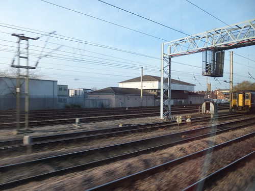

Our equipment was installed in various Power Signal Boxes, including Preston shown in 2013

G.E.C. in Coventry asked us to design and supply telecommunications equipment for a large railway electrification project in Taiwan. Working for the Big Boys mentions some of my experiences and the report here has some recollections from my first visit to Taiwan to assist with commissioning this scheme.

Although we continued to do work in industrial automation (see Visiting Steelworks and Oil & Gas Industry) most work was channeled into telecommunications for railways. British Rail operated a number of large 'Step-by-Step' exchanges to handle internal telephone traffic and they designed their own version of STD (which they called Extension Trunk Dialling) to link these exchanges into one system. We were kept busy maufacturing the racks and relay sets for this scheme.

Two more large projects for G.E.C. followed - one in Brazil, the second in Thailand. These are briefly described in the post Work (part 2). A proposed commissioning visit to Brazil was cancelled at short notice so I didn't get to Brazil until my 'Round the World Two' trip in 2006 (very briefly described here). But I did visit Thailand a number of times during commissioning of that project (the post here outlines the scope, the post here includes a description of a day fault-finding travelling on a railway trolley and the post Thai Railfan Club describes some of the friendships I made).

Standard Telephones and Cables approached us about a complex railway telephone system for use in the Bombay area. We offered to build suitable equipment, but they were keen to manufacture 'in house' so, in the end, we concluded a license agreement. This involved visits to their manufacturing site in South Wales but I was disappointed not to be involved in commissioning the equipment in Bombay - I didn't get to India until 1992 when we commissioned equipment we'd supplied to G.E.C. for a railway telephone system in the Delhi area (see the post My first trip to India).

When we were asked in 1993 to quote G.E.C. for Tunnel Telephone equipment for the Jubilee Line Extension of London Underground, I initially baulked at the idea. None of our existing designs seemed adaptable and, despite the system name, the main function is to provide a high-integrity emergency traction shutdown system. The design challenge appealed to me but I initially assumed the development cost would make our offer uneconomic, as explained in the post Work (part 2). G.E.C. persisted and the supply of Tunnel Telephone equipment became an important, if erratic, source of business but it's so specialised that I tend to think of it as distinct from 'Telecommunications and Jan'. But there is a post called London Underground and Jan.

Related posts on this website

Selecting label 'Work' (or Clicking here) will display all my posts on 'Work' in reverse date-of-posting order. Alternately, Clicking here will display an index list of Titles of posts labelled 'Work' (but this list may not be up-to-date).

[Link URL corrected 26-Nov-2020]

Tuesday, 15 March 2016

Interlude

Although, as far as I’m able, I like to describe these experiences as soon as possible after the event, whilst the memories are vivid, there’s usually some delay. This delay can extend to years, I’m afraid. But I didn’t realise at the time that my internet session on board 'Silver Explorer' on 8th March 2016 would be the last for some days. The next morning, the internet was ‘down’. “Oh”, the ship staff explained, “It’s because we’re close to the mountains”. But even when the ship moved to open water, there was no internet. “We’re looking into it”, came the message. On the 11th March we were told it was a hardware problem which could not be repaired until Cape Town.

I was offered a short satellite telephone call to advise my firm that I couldn’t reply to e-mails already received. A time was booked, early on the 12th March, for me to report to reception, dressed warmly. I was solemnly conducted to the bridge where my guide collected a hand-held satellite telephone and solemnly punched in the number. He then slid open the door to the outside bridge, explaining that a signal could not be received on the covered bridge. This explained the need for warm clothing – there was a strong, chill wind. Although the telephone eventually connected, the link suffered from temporary drop-outsand the howling gale meant that speech my end was almost inaudible. I gathered I’d reached the answering machine, so left a short message.

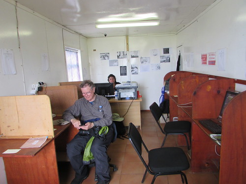
On 15th March, we spent a magnificent day on Tristan da Cunha. A number of passengers, including me, sought out the Internet CafĂ©. Despite an impressive satellite ground station immediately outside with one dish a few metres across and two more small antennae in radomes, the connection was the slowest I’ve suffered for a long time, and suffered periodic disconnections. But, with some perseverance, I managed to send one e-mail to my firm with copies to friends.

Tristan da Cunha: The Internet Cafe with Brenda at her desk and a ship's passenger using WiFi.

I returned very reluctantly to the ship on the last-but-one Zodiac at 6.00 p.m. to discover that, whilst the ‘Silver Explorer’ had waited all day at anchor, they’d managed to point the satellite antenna manually at the satellite, then reset the whole system after which the automatic tracking started to work correctly (at least for now).

Whilst it’s irritating to be out of touch, it’s also important to realise just how amazing the technology is when working, in allowing a ship to connect to the vast resource of the internet from virtually anywhere.

Related posts

All my South Atlantic posts.

My pictures

You can find all my pictures on the trip in the Collection Cape to Cape (still being added to, at the time of writing).

There are a few pictures of the trip in the album South Atlantic Voyage.

['Cape to Cape' collection added 5-Apr-2016]

Monday, 9 November 2015

Electrification Telephone Systems for British Rail

Introduction

In the post Starting my own business I described setting-up a business and being awarded, in 1970, our first order for selective call telephone equipment from the London Midland region of British Rail. This equipment was for use in connection with the provision of new Power Signal Boxes at Warrington, Preston and Carlisle.

Electrification Telephone Systems for Crewe

Because the West Coast Main Line was being electrified at 25 kV 50 Hz, there was also a need for a separate system of 'Electrification Telephones' with its own, distinctively-marked weatherproof telephones connected back to the Electrical Control Room (ECR) located at Crewe. This control room, often called the 'Electric Control Room' or, more usually, just 'ECR' had been built by British Railways as part of the earlier Euston to Manchester Electrification Project. The ECR was located within what was then called Crewe District Electric Depot, on the down side of the Chester line, in between Crewe North Junction and Crewe Steel Works signal box.
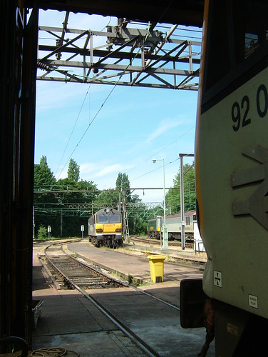
When I returned to the site in 2008, the ECR was still there but the whole site had become Crewe International Electric Maintenance Depot (or Crewe IEMD) operated by E.W.S. See my report here.


Crewe IEMD: View of the yard taken from within the depot in 2008.
The 'Electrification Telephones' were placed at regular intervals along the route for use in the event of emergencies involving the Overhead Line Equipment (OLE). 'Electrification Telephones were also located at OLE outdoor switches and Track Section Cabins (TSC).

In designing the original selective call equipment, we'd had to solve the problem of reducing the power consumption of the signalling decoder so that all the telephones on a circuit could be powered from the telephone line, eliminating the need for batteries at each telephone. But the requirements for the Electrification telephone system were harder to meet since it was also necessary that a number of telephones on the same circuit be able to join in the same conversation. This meant that we needed to reduce the power consumption of the speech circuit so that, when a call was in progress, the telephone line pair could supply power to a group of telephones engaged in the same conversation. After more development, we were satisfied that we could meet these requirements and tendered to the London Midland region of British Rail for a system covering 300 route-kilometres of electrified railway.

We won the tender and in 1971 were awarded the contract to supply Electrification telephones, repeaters, terminal racks and central operator consoles for use on the line from Weaver Junction (south of Warrington) to Carlisle. Production of this new order overlapped the first order for selective call telephone equipment which we'd started to work on in 1970.

Electrification Telephone Systems for Cathcart

The Electrical Control Room at Crewe was responsible for the line as far as Carlisle but electrification was being extended to Glasgow. There was a second Electrification Control Room at Cathcart, around three miles south of the centre of Glasgow. Later in 1971, we were invited to tender for the supply of a similar system for the Scottish Region of British Rail covering 200 route-kilometres of electrified railway controlled from Cathcart. We received the order for that system, too, so we were kept quite busy with three overlapping contracts for selective call telephone equipment.

The requirements for Cathcart included the supply of a Cord Switchboard - a manual switchboard with plugs and jacks to allow a number of calls to be routed simultaneously by the operator. Apparently, a number of earlier Electrical Control Rooms involved the use of a Cord Switchboard and it was a feature the client wanted to retain.

We still had plenty to learn about conventional telephony systems so another period of intense study was called for to enable us to work out how we could adapt a standard Cord Switchboard (designed to interconnect a number of Central Battery telephones to a group of outgoing junction circuits) to our selective call systems (designed to work with keyboards). My starting point, as always, was to consult the two volumes of the book 'Telephony' by J. Atkinson.

Back in the 1970s, there was no internet, of course (there's a splendid brief history of the internet by the Internet Society here). Today, you can research any topic with a few clicks and it's an amazing asset but conventional books are essential as well. There's a brief introduction to telephone switchboards on Wikipedia here but see also A manual telephone exchange: CBS2 on John Hearfield's good-natured and quirky site.

Plessey still made standard cord switchboards so we ordered one of those and, after some sleepless nights, came up with a design for a small sub-rack with reed relay interfaces mounted on plug-in circuit boards which we installed in the back of the switchboard.


A similar Cord Switchboard
(Photo: The Telephone Museum).


In general, British Rail performed their own installation and testing of our equipment but from time to time we were involved in visits to various sites to assist. Needless to say, I was always delighted to have an opportunity to poke about on a railway. However, for the Scottish Region project, whilst the railway were installing the telephones, they wanted us to install the cord switchboard and commission the whole system. Usually, two or three of us would fly up to Glasgow from Birmingham, we'd beaver away for a day then fly back. This was in the days of British European Airways (BEA) before they merged with BOAC in 1974 and became British Airways. Originally, they had Vickers 'Viscount' turbo-props on the route but later they were replaced by the Hawker-Siddeley 'Trident' with three Rolls-Royce 'Spey' jet engines.

I remember one trip when we took a huge, steel deed box as luggage. We'd crammed it with installation materials, tools and test equipment. It took two of us to move it but, to my surprise, the airline handled it without demur. No 'enhanced airport security' in those far-off, innocent days.

We managed to install and locally test the cord switchboard but Scottish Region were having problems completing their lineside cable system over which our telephones would operate so that we were delayed in completing commissioning. I began to understand their problems one day when, having been assured all was ready, we flew to Glasgow. On our arrival, they apologised and said that a section of recently-completed telecommunications cable had been stolen overnight and we'd thus have to postpone our testing. Apparently, they always made sure that cable was jointed the day it was laid, to discourage theft, but sometimes determined thieves would just hacksaw through the cable in a couple of places and carry away a section to 'scrap-in' for the copper. Live power cables were not immune from theft, they added. Perhaps not such innocent days, after all.

I'm pleased to confirm that, eventually, we were able to complete our commissioning.

Electrification Telephone Systems for Hornsey

In 1974, we received an order for one more system of Electrification Telephones for British Rail. This was for the Great Northern Electrification Project for the Eastern Region, covering 100 route-kilometres of electrified railway. This system was controlled from an Electrical Control Room at Hornsey, about four miles north of King's Cross, London. For this project, we supplied telephones with mounting plates plus repeaters, terminal racks and a Cord Switchboard (similar to that supplied for Cathcart). For this project, we also took responsibility for all installation and commissioning, including all the lineside telephones. Handling all aspects of installation gave a new dimension to this project and I'll write a little more when I can.

Wednesday, 4 November 2015

Starting my own business

In the post The World of Work I described my first job at Contactor Switchgear (Electronics) Limited. After a few years there, I'd learnt quite a lot about electronics.


The nameplate of the parent company Contactor Switchgear Limited (Photo: Wolverhampton History and Heritage Website).

With the arrogance of youth, I thought I could do a better job on my own. I decided to set up my own business, with encouragement from my wonderful mother who believed it better to try and fail than spend a lifetime regretting that I'd not made the attempt.

Well, there were some distinctly rocky times ahead but I've had some wonderful experiences and definitely made the right choice.

I started trading as 'J. C. Ford Consultant Electronics Engineer' during 1966. My mother had agreed to my using part of the family home (a modest terrace house) comprising the front room downstairs as an office, plus the cellar as a stores and workshop. For some years, the cellar had been virtually a 'no go' area and it was a major task cleaning it out, painting it and laying on better lighting. The worst part was the small adjunct forming a coal cellar. Although we no longer used coal, removing the evidence of a century's deliveries of solid fuel was rather daunting.

Things were very slow at first - nobody wanted to know. Everybody had told me to 'line up' work from contacts before I left employment but that didn't seem right to me, so I didn't. At first, the situation was rather bleak but, because I'd left my employer on good terms, after a while I was offered some sub-contract design and build work by them which helped a lot.

One of the most remarkable projects was the design and build for my former employers of a Ships Movement Indicator to be supplied to Dover Harbour Board. Because of the sheer size of the panels involved, for a few weeks we ended up taking over most of the living room as well as the office and cellar. Mealtimes became a very cramped affair.

Apart from sub-contract work for my previous employer, I managed to obtain some small industrial automation jobs in the local area. They were interesting, but not very profitable (come to think about it, an awful lot of contracts since have been like that).

An introduction to Gerry Gardner, a successful businessman and marvellous British eccentric, led to a change of pace. His company near Canterbury was bidding on a large contract for a Private Mobile Radio system for Lancashire Constabulary and he wanted us to design special digital selective call equipment for use with Philips VHF mobile radio equipment. Although Philips had their own selective call system, it didn't meet the requirements for the Police Network. In supporting the bid, I had my first ever flight, as described in the post here. Subsequently, I made a number of trips to Lancashire (travelling by land) for meetings or tests. It was a fascinating time, not least because the popular television show 'Z Cars' (which ran from 1962 to 1978) although set in the fictional town of 'Newtown' was actually based on Kirkby and Lancashire police. The comparison of fact and fiction was enthralling.


'Z Cars' Opening Title Logo
(Fair use claimed).


I was treated with great kindness by Gerry Gardner and often visited his headquarters which were in a large thatched barn next to his rambling, medieval home. Because of the success of the system for Lancashire Constabulary, we produced other systems for Fire Authorities and the Port of London Authority.

A few people I'd known at Contactor Switchgear (Electronics) Limited who had also moved on came to work with me and it was clear that I'd have to find alternative premises.

I'm afraid I made a rather odd choice, renting most of the former British Waterways canal depot in Broad Street, near the centre of Wolverhampton. This had originally been built for the canal carrying company of Fellows Morton and Clayton Ltd. There was a substantial two-storey brick warehouse building with offices, ground floor warehouse (including an internal canal basin!) and an upper floor warehouse reached via a wonderful spiral staircase. One wing of this building was retained by British Waterways Board as their local Estates Office. In the yard there was a toilet block and a small two-storey building which was already let to an elderly man who made canvas shop blinds. The business had originally made and repaired the large canvas sheets used by freight-carrying narrow boats. The accommodation was completed by a fairly modern 3,000 square foot steel-framed warehouse clad in corrugated cement asbestos sheeting. Finally, there was an outside canal basin.

Needless to say, charming as the property was, it was not particularly suitable for manufacturing electronics equipment. The site was huge compared with our immediate needs but I'd taken the precaution of ensuring that we could sub-let space we didn't need. I suppose the steel-framed building would have been easiest to adapt for our use, but we'd already had interest from a steel fabricating firm in renting that building and soon concluded a letting agreement with them. Rather later, a small mechanical engineering firm rented part of the upper floor of the main warehouse.

For our own needs, partitions and ceilings were erected in part of the ground floor warehouse to provide stores and production areas. At about this time, my former employers had decided to 'slim-down' their electronics operation, resulting in their maintenance manager disposing of a quantity of second-hand workbenches, chairs, shelving units and partitions. Unexpectedly, he offered to sell them to me at very reasonable prices and they proved invaluable in moving into our new home.

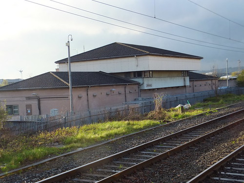
The upper part of the main building at Broad Street Depot, as seen from the adjacent railway station in 2013.

In 1970, British Rail approached us about the possible supply of selective call telephone equipment for the electrification between Crewe and Carlisle. Having produced successful systems for use over radio, in my ignorance I imagined that a similar system for use on telephone circuits would present little challenge. A steep learning curve followed as we grappled with the special problems of line communications.

The railways had previously used a system from Plessey which used mechanically resonant reeds to detect a specific calling frequency. Disadvantages were that each telephone installation needed a different resonant reed and its own battery power supply. In addition, when used outside, a large weatherproof housing was required to mount the batteries, the control unit and the telephone instrument.

The Post Office (which wasn't privatised as British Telecommunications until 1981) had approved a weatherproof wall telephone made by Plessey generally referred to as the '745' (there's information on this telephone here).

Our design aim was to cram everything inside this telephone instrument, provided that we could reduce power consumption sufficiently to allow the telephone to be line powered using a variation on established Central Battery techniques. A small number of voice frequencies transmitted as a sequence of tones would allow a single type of selective call decoder to be configured (on site, if necessary) to respond to any desired code. The proposed technique offered the possibility of significant economies. Just when we'd solved the technical problems, we were hit from another direction - component supply problems. I've written about this in the post If it were easy, everyone would do it.

We won the contract with our innovative approach and were kept busy over the next three years building the required equipment in connection with the Power Signal Boxes being installed at Warrington, Preston and Carlisle covering 400 route-kilometres of railway. We supplied our 'C.B. Selective' telephone equipment complete with repeaters, terminal racks, spares, maintenance equipment and training services.

Warrington Power Signal Box, pictured in 2012.

More.

Saturday, 12 January 2013

My First Trip to India (continued)

In the earlier post My First Trip to India I briefly wrote about my first experience of India when I was assisting G.E.C. in commissioning telecommunications equipment for the Delhi Ring Project. I thought it was time to add a little more.

I flew to Delhi in May 1992, in the height of summer, returning nearly seven weeks later just as the Monsoon arrived in Delhi. It was a very hot summer in Delhi that year - temperatures of 45 degrees Celsius (114 degrees Farenheit) are expected but it seemed that every day people in the G.E.C. office which was our base said "It's 120 today!".

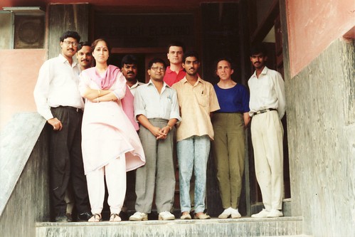
Jan poses with G.E.C. staff outside the offices in Delhi.

The Delhi Ring Project

G.E.C. were installing a new Electronic Control Centre (ECC) near New Delhi station to control the complex railway network in the area operated by Northern Railways. This included a circular suburban line called the Delhi Ring together with a number of main lines radiating from Delhi. Various new telecommunications cables had already been provided from the ECC along the routes to be controlled and selective ringing omnibus telephones had been supplied by others and installed at signal boxes, stations and level crossings. When GEC started to commission the new telecommunications facilities, a number of problems with the audio transmission were revealed.

At that point my company, Ford Electronics, became involved. We were invited to propose changes simple enough to be retro-fitted on site which would provide good-quality speech throughout the system. Our solution involved the use of Loaded Cable Pairs, correct Build-Outs at equipment locations and a number of 2-wire Amplifiers to restore correct signal levels.

The re-arranged telecommunications circuits are shown in the sketch below.

Click on image for larger view

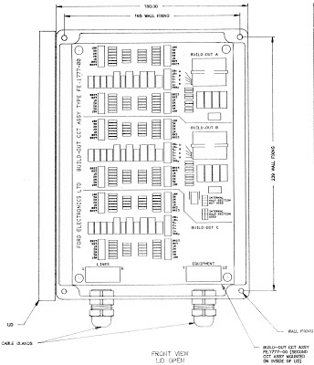
On a short timescale we acquired the necessary 2-wire amplifiers and both designed and constructed the necessary Build-Out Units. Each unit had provision for three build-outs and these could be readily configured to suit each location by a series of links. The Build-Out Unit was in the form of a single assembled printed circuit board mounted in a rugged plastic housing intended for wall mounting adjacent to the telecommunications terminations in the various equipment rooms. The drawing below shows the appearance of the Build-Out Unit with the lid removed.

Click on image for larger view


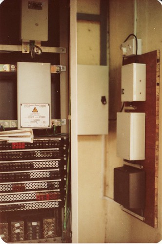
In the various equipment rooms, the equipment which was added as described above was wall-mounted on a wooden board, seen on the right in the picture below.


Railways around Delhi

As I commented in the earlier post, I was amazed to find steam haulage was still in use since I'd assumed all steam had been eliminated and yet here I was, transported back to the '60s when steam was being eliminated in Britain. On my return to the U.K., a short article entitled 'Steam in India' was published in the September 1992 edition of 'Lionsheart' (the Occasional Newsletter of the Old Locomotive Committee). Since this is the only contemporary account of my visit, I thought it might be worth repeating a section of the article here:-
I saw a little of Indian Railways as they are today today. New Delhi station is all diesel and electric. Electrification is 25 kV a.c. and I was able to travel on 'the fastest train in India' - the electric-hauled Shatabdi Express - at least as far as Agra.

But Delhi Junction still has a number of steam workings. There's a metre-gauge terminus served by steam and diesel standing next to a broad-gauge through station with steam, diesel and electric workings.

Europeans are regarded with friendly curiosity and I found it easy to be invited onto the footplate but soon discovered that not all drivers speak English! However, English names seem to be used for the driving controls so I was able to establish my unlikely credentials as a female enthusiast by the 'Naming of Parts'. Whilst photographing a metre gauge light engine during a lunch break (a Class 'YG' 2-8-2), the driver signalled me to engage reverse gear and open the regulator. I happily pottered out of the platform, thinking we were carrying out a shunt. It eventually dawned on me that we were 'Rightaway the Shed' a few miles distant for disposal! It took a little time at the shed to locate an English speaker and arrange a trip back to my starting point on a diesel-hauled empty stock working, but it was a wonderful, if unexpected, experience.

My friends at railway headquarters said that they would arrange an official footplate trip for me, but they were not so sure about my request for 'hands-on'. In the event, because of pressure of work, it was 6 p.m. on the day I was leaving before I was able to make my official footplate trip.

They'd chosen a steam-hauled Delhi - Haridwar working. As always, the platform was crowded as I made my way along the length of the train to the locomotive - a broad-gauge class WP 'Pacific'. This Indian Railways Standard design was only introduced in 1947, so it is rather modern by OLCO's standards. But perhaps the Editor will find space in a future edition for a description of my all-too-short trip.
This picture appeared in the July 1992 of 'Lionheart', with the caption "Our photograph shows Jan Ford in India recently, looking surprisingly happy after suffering a signal check whilst at the controls of a broad gauge Class WP 'Pacific' from Delhi to Shahdara".

National Railway Museum, Delhi

It was on this trip that I made my first visit to the National Railway Museum in New Delhi. The section of the 'Lionsheart' article dealing with the Museum is repeated below:-
My recent business trip to India gave me an opportunity to visit the Railway Museum at New Delhi and see the twilight of steam on the main line around Delhi.

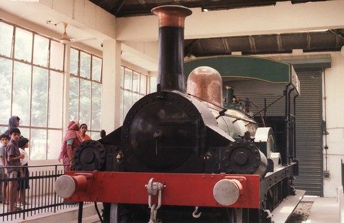
The most famous exhibit in the Railway Museum at Chanakyapuri is 'Fairy Queen', built by Kitson, Thompson and Hewitson in 1855. At one time she was regarded as the oldest steamable locomotive in the world. She was saved through the intervention of Mike Satow, who remains a respected consultant to the museum. This locomotive and a half-sectioned 'A' class broad gauge 4-6-0 share a glass-fronted building of their own. Smaller items and models are housed in a roundhouse-style museum building. All the other exhibits are displayed around a ten-acre outdoor site.

By coincidence, the last issue of LIONSHEART carried a letter from Mike Satow pointing out the link between LION and 'Fairy Queen' in that both locomotives have back-to-front reversing levers. 'Fairy Queen' is built for the Indian 5ft 6in broad gauge, which gives her a squat, powerful appearance. The running boards running the length of the locomotive are noteworthy. Water is carried in well tanks (like 'Bellerophon').

The French built 'Ramgotty' is interesting, both for her wooden brake blocks and Gooch motion operated from outside eccentrics (shades of 'Bellerophon' again).

There are a number of British-built locomotives. The largest locomotive is the Manchester-built Beyer Garrett from the Bengal Nagpur Railway. I imagine our friends at the Museum of Science and Industry in Manchester would be delighted to repatriate that one!

The oddest exhibit is probably the Patiala State Monorail Trainway locomotive, running on a single guidance rail in the centre with two unflanged wheels on the outside. Built in 1908, this locomotive is still steamable.

An excellent guide to the exhibits at this museum, written by Mike Satow, can be found in the May 1977 edition of 'The Railway Magazine'.
This picture of 'Fairy Queen' (along with other pictures) appeared in the July 1992 edition of 'Lionsheart'.

I made another visit to the Railway Museum in February 2006 and the pictures I took on the second occasion are linked in the 'Photographs' section below.

Sightseeing

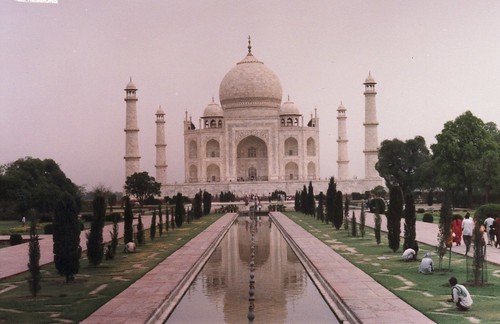
In the whole time I was there, we worked seven days a week to get the job finished. Time off was confined to a few half-days and two whole days. The first whole day off was a Public Holiday. This gave me the opportunity to visit Agra by train. I went to the Taj Mahal, the Red Fort, the 'Baby Taj' and Fatepur Sikri.

The Taj Mahal at Agra.

On the second day off I was even more ambitious and flew to Varanasi, the Holy City on the River Ganges which was formerly called Banares.

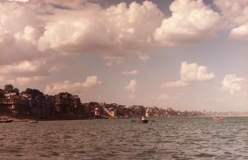
The city of Varanasi, viewed from the River Ganges.

Links to Sets of Photographs

Broad Gauge around Delhi.
Shahdara Junction, Delhi.
Metre Gauge around Delhi.
Driving a 'WG' in India.
National Railway Museum, Delhi (1992)
National Railway Museum, Delhi (2006)
Delhi Ring Project
Varanasi, India.

Monday, 5 December 2011

Audio Visual Installations at the Museum of Liverpool

Click on any picture below to see the un-cropped image.

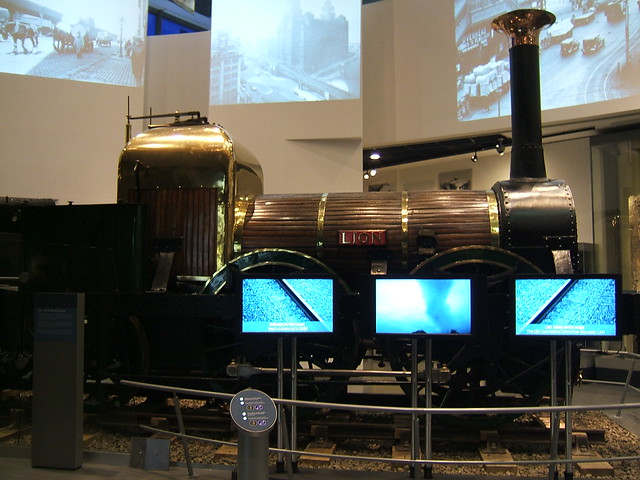
In the post 'Royal Visit to the Museum of Liverpool', I described the state-of-the-art Audio-Visual systems used around the museum, which use a number of high-definition flat screen displays and large, projected images. The picture below shows the facilities associated with just one exhibit - the locomotive 'Lion'.

At high level, there are three large displays using Panasonic projectors. In the above picture, views of Liverpool are being shown but, at other times, pictures of 'Lion' are projected. In front of the locomotive, three high-definition flat screens are provided. In the foreground, a pedestal has pushbuttons allowing visitors to select one of two presentations (with or without subtitles and signing).

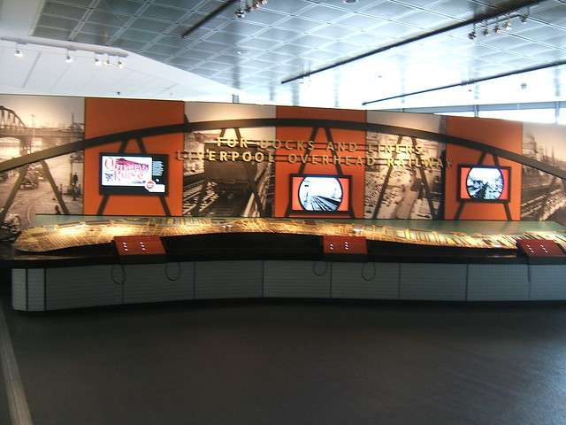
The Liverpool Overhead Railway display shown above also has complex A.V. facilities. The are three high definition flat screens, three control panels with multiple selection buttons and six handsets.

All the A.V. systems are controlled through a comprehensive computer network around the museum provided by Cisco. I was able to visit one of the four equipment rooms in the museum where the A.V. control equipment is situated.

The left and right cubicles in the above picture are associated with control of the Audio Visual presentations. The central cubicle provides a 'conventional' computer network. The Audio Visual equipment includes BrightSign High Definition Media Players, Adtec 'signEdje' High Definition Digital Signage Players and WOTbOX Solid State Audio Players. A slide-mounted Laptop Computer allows diagnostics and programming of all features.

There's a small set of pictures of the A.V. equipment here.

Wednesday, 29 September 2010

Railways on the Air 2010

The 'Radio Shack' at Shackerstone viewed from an arriving train.

I was unaware of this interesting annual event until I turned up at Shackerstone on 25th September 2010 and found members of Hinckley Amateur Radio and Electronics Society on Platform 2, in a tent sprouting a very professional-looking aerial system.

Every year, amateur radio enthusiasts set up temporary radio stations at participating preserved railways and try to collect as many 'contacts' as possible. For more details, click here.

There were a few pictures but they're currently missing, sorry .

Thursday, 24 January 2008

10-line Key and Lamp Unit

10-line Key and Lamp Unit in use at Shackerstone. Click on image to enlarge.

This key and lamp unit allows the signalman to speak to any one of ten incoming 2-wire telephone circuits. This type of equipment in varnished wooden cabinets was already old-fashioned when I started to learn about telecommunications in the 1960s. The two volumes of 'Telephony' by Atkinson were the telecommunications 'Bible' and gave an insight into the principles used.

On the left of the box the operator's handset can be seen, hanging from the 'Gravity Switch'. Originally, this would have been a heavy, bakelite 'Hand Micro-Telephone' ('HMT') but it has been replaced by a more modern, and much lighter, '700' series model. The handset cord terminates in a Plug which connects with a Jack mounted on the cabinet.

The horizontal row of coloured knobs in the middle of the front of the cabinet are 3-position Lever Keys, one for each outgoing line. They're often called 'Kellog Keys' after the original manufacturer. Lifting the key upwards sends ringing current to the associated line, so as to ring the bell of the remote telephone. The key is biased so that it returns to the normal position as soon as the operator lets go. This is called 'Non-locking' action. Pushing the key downwards connects the operator's handset to the associated line, so that two-way speech is possible. In this direction, the key will stay down when the operator lets go, leaving the operator with one hand free during the conversation - useful if written notes are required. This is called 'Locking' action. At the end of the call, the operator flicks the lever key back to the central position, disconnecting the telephone he was speaking to.

Below the row of lever keys is a metal 'Lamp Strip'. This mounts ten lampholders accepting plug-in filamentary lamps, usually the British Post Office No. 2 'wedge' lamp. An opal white glass lens fitted in a clip-in brass mounting is fitted in front of each lamp. When any of the remote telephones initiates a call, the appropriate lamp glows white and a buzzer (common to all lines) sounds until the operator pushes the associated key down to the 'SPEAK' position. This action silences the buzzer and allows a conversation to take place.