skip to main |
skip to sidebar
The English Electric 350 h.p. diesel-electric shunter is a rugged, useful locomotive. It became the 'Class 08' with variants classified 10, 11. These notes were specifically prepared back in 2002 for 13029 at Birmingham Railway Museum and details will vary on other locomotives. I have added a link to brief British rail training notes.
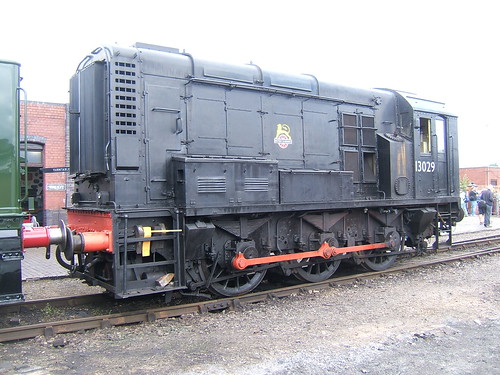
English Electric 350 h.p. diesel electric shunter 13029 (later Class 08) at Tyseley Locomotive Works. Around 1990, this was the first diesel I was passed to drive and was very handy for shunting early in the morning when the 'steamers' were still 'brewing-up'.
History
Class: 08/0
Built: BR 1958-1962.
Engine: English Electric 6-cyl 6KT of 400bhp (315kW).
Weight: 49 tonnes.
Brake force: 19 tonnes.
Maximum tractive effort: 35000lb (156kN).
Power/control equipment: English Electric Two EE505 traction motors. Double reduction gear drive.
BR Route availability: 5.
Maximum speed: 15 mph, except certain 20 mph.
Fuel: 668 gallons.
Pre-start checks
Check axlebox dipsticks for oil level and replenish if necessary. Oil coupling rods.
Open battery box on left side of locomotive and close battery switch. Open battery box on rightside of locomotive and close battery switch, additionally visually check the condition of the contacts on starter contactor.
Check main fuel tank gauge. There should be at least 50 gallons, to avoid sediment being drawn from the main tank. Enter cab and ensure handbrake applied. Check service tank fuel gauge. There should be at least 20 gallons, to avoid sediment being drawn into the engine fuel system. As necessary, operate the hand fuel transfer pump to replenish the service tank. Insert master key. Operate the hand pump on the rear wall of the cab for 30 - 45 seconds to pressurise the oil system.
Insert the master key and move to the non-locking 'EO' (Engine Only) position. Further operate the key to the non-locking 'start' position and hold in this position until the engine is firing correctly. Allow the key to return to the 'EO'position and then move it into the 'off' position, in which the battery will be re-charged and the main compressor will start. Wait until the main reservoir pressure (indicated on the duplex brake gauge) has reached 70 psi. Move the straight air brake application valve into the down (applied) position. Full brake pressure should be indicated on the duplex gauge.
The DSD is checked by placing the master direction controller in forward or backward, pressing the foot treadle and moving the driver's application valve for the straight air brake into the up (release) position. On the duplex gauge, the brake needle should fall to zero, indicating brake release. Release the DSD treadle and observe that, after a delay of a few seconds, the brake is automatically applied.
To release the brake after the test, place the driver's valve in the 'brake applied' position, depress the DSD treadle and move the driver's valve back to the release position.
To release the handbrake, partially apply the straight air brake then wind off the brake. Ensure the direction switch is set correctly for the intended movement, lookout to ensure it is safe to move, sound the horn and move to power controller into first notch. Pause at the first notch position and ensure that the motor contactor has energised (audible 'clump' from the control panel), then gently advance the power controller as necessary for the movement, checking the total generator amps as shown on the current meter.
Britsh Rail Mechanical Department, York training notes
These can be viewed, printed or downloaded here.
They comprise 9 pages:-
1. General Layout Diagram 200
2. Cooling Water System Description
3. Cooling Water System Diagram 201
4. Lubrication System Description
5. Lubrication System Diagram 202
6. Fuel System Description
7. Fuel System Diagram 203
8. Air and Vacuum System Description
9. Air and Vacuum System Diagram 204
The Mutual Improvement Classes (MIC) of the old steam railways continue for today's preservation volunteers. This article, taken from notes of talks given by Jan in 2002, is one of a series about working on preserved railways. You can display them all by clicking here or see an index of article titles here.
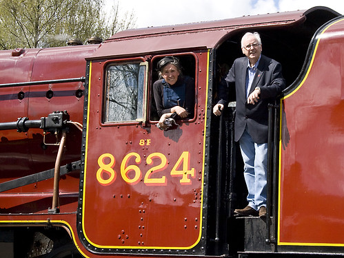
Pete Waterman and Jan on the footplate of 8624 at Peak Rail in 2010 (Photo: Sheila Rayson).
The Passed Fireman is normally rostered as a fireman but, having become a Passed Fireman, he is available to act as Driver when required. The candidate for passed fireman will be expected to have had significant experience (the required experience depends upon the railway) of working around engines, moving through the grades of cleaner, passed cleaner and fireman. The safety procedures necessary on locomotives should have become second nature and the candidate should be relaxed and at ease on the footplate, whilst remaining alert and aware of everything going on. Monitoring the state of the boiler, correct use of the injectors/dampers/blower should all come readily, together with an easy familiarity with firing. This allows the candidate, once passed for driving, to adequately supervise his fireman and, where necessary, give assistance.
A driver has to be in control - of him or herself, the fireman, the locomotive and the train. A good driver radiates quiet confidence which comes from mastery of driving and firing and a thorough understanding of the design and operation of all aspects of the locomotive.
This is quite a task which is why, before the Second World War, a railwayman could spend twenty years or more on the footplate becoming thoroughly conversant with everything he might need to know. In present day preservation, promotion to driver is likely to come much earlier. A professional railwayman will have spent every working day working on locomotives - a volunteer, however keen, is unlikely to have spent more than one or two days a week, if that. Accordingly, you need to compensate for the relative lack of experience partly by seeking a thorough understanding of the engineering theory underlying locomotive design and partly by consciously avoiding the complacency which familiarity may encourage. Safety comes through recognition of your own relative inexperience.
Locomotive Preparation and daily examination
On taking charge of a locomotive, you must ensure that the locomotive is in a safe condition - mid gear, cylinder drain cocks open, handbrake hard on, regulator closed and that the gauge frames are in the working position with sufficient water showing in the glass. You must make yourself responsible for the safety of the booked fireman and any rostered preparation crew working on the engine. Ensure that they report to you on arrival and do not leave for other tasks without your permission. You must set a good example for them to copy and not allow yourself to slip into sloppy or dangerous practices.
Boiler management during preparation is crucial and the driver must be able to supervise his fireman adequately, giving help and advice so that the fireman becomes more confident and more skilled. Effective preparation of the smokebox (char removed and door airtight), ashpan (ash removed and dampers working properly) and fire (clinker removed and firebars in good order) is vital to ensure complete combustion of every shovelful.
Although drivers will frequently allow their fireman or preparation staff to oil round the locomotive to gain experience, the daily examination is something a driver will want to perform himself. Be methodical, work round the engine checking for anything which may later become a problem. Examples are fractures, cracks, unexpected or unusual wear, damaged, bent or misplaced components, missing locknuts, cotters or split pins and, particularly, displaced spring hangers or broken springs. Check for any leaks (steam, water or oil). As far as oiling is concerned, ensure that any missing corks are replaced and check the condition of a sample of the trimmings. If possible, carry a small selection of corks so that any found missing or damaged can be replaced without the need to make a special journey. If a mechanical lubricator is fitted, ensure that this is filled with the correct grade of oil has been used and, when a priming handwheel is fitted, ensure that this has been operated so as to fill the oil delivery lines. Where a sight feed or hydrostatic lubricator is fitted, this must be carefully filled with clean oil, ensuring that it really is full.
Traction and Adhesion
We walk by trying to slide a foot backwards along the ground. Normally, there is sufficient friction between sole of the shoe and the ground to prevent sliding. Instead, the foot stays where it is but the body is levered forwards. However, if we try the same thing on ice, the friction between shoe and ice is much lower and the usual result is that the foot slides backwards. We can walk on ice only by deliberately reducing the sliding force generated by the muscles so that it is too small to break down the reduced level of friction between shoe and ice.
Moving a locomotive is a bit like walking on ice. A locomotive moves by applying torque (a turning force) to the driven axles. At the wheel tyre, this force attempts to slide the wheel on the rail. Under suitable conditions, sliding does not occur but instead the torque levers the engine forward so that a new part of the wheel tyre is in contact with the rail and the process continues. The force applied at the rail/wheel interface is proportional to the total area of the pistons on which the steam operates, the pressure of steam employed and inversely proportional to the diameter of the driven wheels. This force is usually termed the Tractive Effort of the locomotive, commonly expressed in 'pounds of force'.
Examined microscopically, neither the railhead nor the wheel tyre are smooth. For successful motion, there must be sufficient friction on the small area of contact between the tyres of the driven wheels and the rail for the engine to lever itself forward. The total friction is proportional to the number of driven wheels and the weight bearing down on each wheel - up to 10 tons or more on a large engine. If the torque applied to the wheels is progressively increased, it eventually exceeds the friction between wheels and rail and, at this point, wheelslip occurs. It is important that the driver reacts promptly to wheelslip to prevent damage to the engine by temporarily closing (or partly closing) the regulator. Remember that the response to closing the regulator will not be instant. The steam already in the main steam pipe, superheater elements (if fitted) and the steam chests will continue to drive the wheels for a time. Where a locomotive is fitted with a steam brake, some drivers will rub the brake to inhibit the slip and then reduce the braking effort as the slip dies away.
A cautious driver will avoid slips on starting by gradually opening the regulator until there is sufficient power to start the train moving. Once the train is rolling, power can be further increased to accelerate the train away. Variations in boiler pressure will clearly affect the power available - a larger regulator opening will be needed if the boiler pressure is lower than normal.
Clearly, the heavier the train or the steeper the gradient, the more power must be applied before the train moves away and the driver has to juggle the power to provide sufficient force to move without slipping. When the load is at the limit of adhesion, brief intermittent slipping may be inevitable.
The actual friction will vary according to the condition of the wheel tyres and the condition of the railhead. Rain has a profound effect and a slight drizzle will drastically reduce the friction between rail and wheel. During heavy rain, friction will tend to improve as the rain scours away the oil and grease which is normally present. Curvature of the track is also a factor. On a curve, the flanges of the driven wheels pressing against the outer rail may locally increase the friction available, but the rolling resistance of the train on the curve will also increase, requiring more power in any case. When moving through pointwork, values of rail/wheel friction on the driven wheels will fluctuate as the wheels pass through switch rails, check rails and crossings.
Engine weight diagrams show the theoretical static loads carried on each axle. The weight carried by the driving wheels determines the friction between tyre and rail and thus the amount of power which can be absorbed before wheelslip occurs. But, in traffic, the actual weight on each axle can vary quite widely, particularly if an engine has been roughly handled or spring characteristics are not ideal. Some locomotive designs include compensating beams to share the load between a number of axles but many types have independent suspension on each wheel.
Another factor to consider is weight transfer. Different designs and wheel arrangements have varying characteristics but many locomotives tend to rise up at the front when starting away with a load on the rear drawbar. This alters the distribution of load between the various axles. In a 'Pacific' the effect is unhelpful as it tends to 'unload' the coupled wheels and increase the weight on the carrying wheels at the rear, reducing the weight available for adhesion and thus the amount of power which can be applied without slipping. Any irregularities or undulations in the track such as a 'dropped' rail joint or pointwork in need of packing will also encourage this weight transfer effect, increasing the likelihood of slipping.
Although slipping is usually associated with starting a train away, high speed slips can occur, for instance when a locomotive running near the limit of adhesion hits a bad rail joint; a driver must be constantly prepared to take corrective action.
Braking
There's an old railway maxim 'Any fool can start a train, but it takes a driver to stop one'. As a fireman, you will have studied braking systems, but, in preparation for driving, you should review your understanding. When you're on a greasy rail with a few hundred tons on the drawhook is no time to realise that you've insufficient brake power! You must ensure that you are fully conversant with the various types of brakes, the method of testing them and the problems that you may encounter day-to-day. Remember, as a driver, there usually no-one to turn to for advice and you will have to decide how to tackle any situation.
Timekeeping and Economy
Drivers can be divided into three types, according to their response to a train which is delayed in starting. One type takes the view 'oh well, we're late already, a few minutes more won't hurt' and allows the delay to increase. The second type carefully maintains the scheduled sectional times but arrives as many minutes late as departure was delayed. The third type goes all out to recover the lost time. The third type of driver produces the most stirring runs and is the most widely reported but the second type of driver is usually the most economical. There is normally a price to pay in working locomotives to the limit: efficiency often deteriorates badly and water and coal consumption can be badly hit. Maintenance costs can also rise drastically due to increased wear. The expert driver will balance all these factors and will rarely, if ever 'thrash' an engine. A good driver will take pride in working to the schedule he is given in an economical manner and without working the engine harder than necessary. Drivers must thus be familiar with the factors which affect economy and must be able to choose the best method of working with any engine in any situation.
Boiler management crucially affects economy and the driver must supervise his fireman, giving help and advice where needed. Dampers and secondary air must be carefully regulated and the rate of firing adjusted to the needs of the job. The locomotive should never be allowed to blow-off as this represents a loss of coal and water. Boilers are usually most efficient when operated near their working pressure and the chosen pressure should be maintained as constant as possible for best economy. Good results on the road are often obtained by running the boiler at a constant rate of steaming. As the gear is linked-up, speed rises and when the cut-off is lengthened for hill climbing (using more steam per stroke) speed is allowed to fall, keeping demand for steam more-or-less constant.
Economy is best achieved by using steam expansively in the cylinders. When starting away, a locomotive might operate at a cut-off of, say, 75%. This means that the piston will complete 75% of its stroke before the steam supply is shut off by the steam valve valve. The volume of steam in the cylinder is then expanded by 1/3 as the piston completes its stroke before being exhausted through the blast pipe to the chimney. Once under way, the cut-off might be brought back to, say, 50%. This means that the steam valve will now cut off the steam supply when the piston has completed only half its stroke. The half cylinder-full of steam will expand itself to fill the cylinder - expansion to twice the original volume - before the steam valve opens to exhaust the used steam. As steam is expanded in the cylinder, it continues to do work in pushing against the piston and the steam is cooled. The exhaust steam is thus cooler when an engine is 'linked up' to an earlier cut-off than in full gear and this means that more work is extracted from the steam. In addition, when linked-up, less live steam is drawn from the boiler on each stroke, allowing the locomotive speed to increase without demanding a higher rate of steaming from the boiler. What must be avoided is expanding steam so much that the temperature falls sufficiently for the steam to condense into water. This not only chills the cylinder Casting (wasting syteam on the next stroke in warming the cylinder again) but leaves water in the cylinder which may not be swept from the cylinder during exhaust as more fluid steam would be. The advantage of using superheated steam is that its initial temperature is higher than saturated steam at the same pressure and so a greater expansion ratio may be used without risk of condensation in the cylinder.
When an engine is in full gear, the travel of the steam valve is at its maximum and so the maximum possible openings are obtained during admission and exhaust. As the gear is linked-up, the travel of the steam valve is shortened so that steam is cut off earlier in the piston stroke. But this means that the maximum possible opening no longer achieved and making complete exhaust of the used steam more difficult. This tends to require more live steam to counteract the back pressure produced by the exhaust steam as it is forced out through the restricted exhaust port, impairing the economy of the engine. Valve travels on slide-valved engines were in the order of 4 - 5 inches. Because of the design of the unbalanced steam valve, shorter valve travel meant less work was wasted in moving the valve against friction. Balanced slide valves allowed larger designs to be produced but these gave way to balanced piston valves where much less work was wasted, allowing the advantages of long-lap, long-travel valves to be exploited.
