History
The Great Northern and City Railway (GN&CR) was formed in 1892 to build an underground electric railway from Finsbury Park, on the Great Northern Line, to Moorgate Street in the City of London. Initially, the Great Northern Railway supported the scheme and, to allow through running of main-line stock, the double-track line was built mainly in twin 'tube' tunnels, each with a diameter of sixteen feet. However, problems financing the project combined with disagreements over joint operations meant that the line as built terminated in underground platforms at Finsbury Park underneath the Great Northern Railway station.
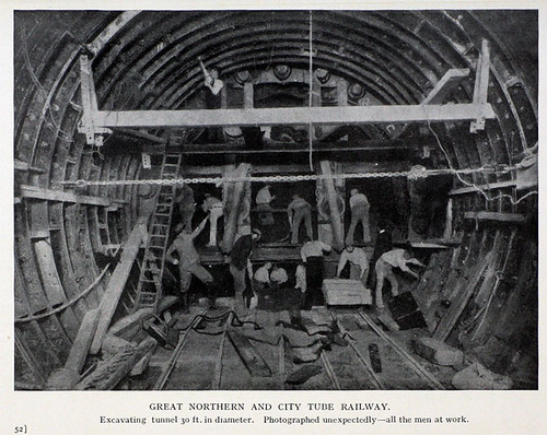
Great Northern and City Railway - driving 30 foot diameter tunnel section (Photo: Grace's Guide).
The line opened in February 1904 over a distance of three and a half miles from Finsbury Park to Moorgate in the city of London. Although powers had been obtained in 1902 to extend from the southern terminus around 500 yards to the Bank of England, this plan was abandoned after only part of the tunnel had been constructed. The isolated nature of the line prevented the railway from running at a profit but it was successful enough to be acquired by the Metropolitan Railway in 1913. In 1933, London Passenger Transport Board took control and the line became an isolated section of the Northern Line, called the 'Northern City Line'. It would have formed part of the proposed 'Northern Heights Extension' but this scheme was abandoned.
In 1964, Drayton Park became the northern terminus, allowing the original underground platforms at Finsbury Park to be used by the Victoria Line then being constructed. Highbury & Islington station was remodelled to allow interchange between the new Victoria Line and the Northern City Line. In 1970, the line was renamed 'Northern Line - Highbury Branch'. Around 1975, London Underground agreed to transfer the line to British Railways. However, before London Underground withdrew the service, Moorgate was the site of the worst London Underground train accident on 28-Feb-1975, killing 42 passengers and the driver. The excellent Railways Archive site has a summary of the report on this accident here, with a link to the full report which is well worth studying to understand the meticulous investigations carried out after major accidents.
British Railways Eastern Region converted the line from Drayton Park to Moorgate for their use, with 750 volt d.c. third-rail electrification and provided a connection from Drayton Park to the surface station at Finsbury Park, with 25 kV a.c. overhead electrification allowing the Moorgate Branch to form part of the Great Northern Suburban Electrification Scheme, finally realising the ambitions of the promoters of the Great Northern and City Railway in 1892! In 1976, services commenced to Welwyn garden City and Hertford north, extended to Royston in 1978. At that time, the Electrification Control Room (ECR) supervising the area was at Hornsey.
There's an interesting PDF by the London Underground Railway Society celebrating 110 years of the Northern City Line 110 YEARS OF THE GREAT NORTHERN & CITY published by here.
Rolling Stock
Electric Multiple Units were used from the opening in 1904, built by Brush (Loughborough) and The Electric Tramway & Carriage Works (Preston). By 1939, these units had been withdrawn and normal tube stock was in use.
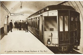
Original rolling stock on Great Northern and City Railway.
Since 1976, the line has been operated by dual-voltage class 313 EMUs running on the third rail system with tripcocks over the tunnel section and the overhead line equipment north of Drayton Park station. The EMU are arranged as 3-car sets with two driving motor cars and a trailer car. In peak periods, two 3-car sets work in multiple. Each motor car is equipped with four GEC G310AZ 82.125kW motors. For more information, see the Wikipedia article here.
This rolling stock is about to be replaced by a variant of the Class 700 'Desiro City' dual-voltage Electric Multiple Units, the Class 717 which is fitted with end doors for use on the Northern City Line, allowing passengers to be evacuated via the Moorgate Tunnel (as is possible with the 40-year old Class 313). At a recent Rail Industry Information Day (described here), I was surprised to find a full-sized Class 717 cab.
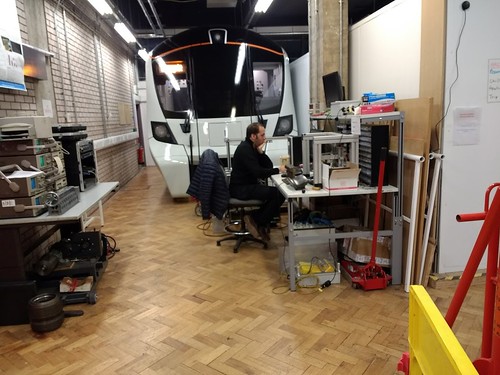
Rail Industry Information Day, 2018: Class 717 cab.
Electricity supply
Originally, power for the Northern City Line was produced at a dedicated generating station on the surface at Poole Street, roughly halfway along the route, directly above the twin tunnels. As mains electricity became available, the generating station was closed, being replaced by two traction sub-stations located at Finsbury Circus (adjacent to Moorgate station) and Queensland Road (adjacent to Drayton Park station). Around 1920, the abandoned generating station at Poole Street was converted into film studios for Gainsborough Films. At the time of my own first visit during a survey in 2006, the site was being re-developed as apartments.
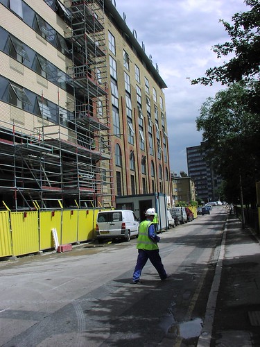
Former Gainsborough Studios, pictured during conversion into apartments (Photo: Thales).
Current was originally supplied at 575 volts d.c. using a fourth-rail system with each conductor rail placed outside the adjacent running rail (as on the Earl's Court experimental electrified train). By 1939, the conductor rail system had been converted to the standard London Underground fourth-rail system, as described in the posts London Underground - Traction Power Distribution and Fourth Rail Electrification. Transmission losses at 750 volts d.c. are relatively high and, to avoid excessive voltage drop, Traction Sub Stations (TSS) have to be located quite close together. When British Railways took over the Northern City Line, in addition to converting current collection to third rail, the power supply was upgraded. The conductor rail is divided into traction sections extending from one TSS to the next. Each section is double-end fed with d.c. from rectifiers at both Traction Sub Stations, to help to minimise voltage drop, particularly when more than one train is in a traction section.
Traction Sub-stations
The practical arrangement of a typical TSS with two rectifiers is illustrated in Figure 2.2 below. TSS for third rail conductor systems, are simpler than for the London Underground fourth-rail systems, since circuit breakers only need to switch the feed to the conductor rail.

The substation has two d.c. busbars linked or isolated by a coupling breaker. Each rectifier and each road supplied is associated with a circuit breaker. At most TSSs, the coupling breaker is normally closed so that both rectifiers and all four roads are connected together to minimise voltage drop. The TSS at Finsbury Circus and Queensland Road are simpler than the diagram, since each TSS only controls two traction sections.
Track Paralleling Huts
At some locations, Track Paralleling Huts (TPH) may be provided, rather than a full TSS. Each conductor rail is broken to form a section gap, but normally circuit breakerss are closed to connect together all conductor rails. Again, the aim is to reduce the voltage drop as a number of rectifiers can contribute current to each traction section. The arrangement is shown in Figure 2.3 below.

Jan's involvement
In 1974 my firm supplied an Electrification Telephone system for the 25 kV a.c. overhead electrified parts of the Great Northern Suburban Electrification Scheme, controlled from an Electrification Control Room (ECR) at Hornsey, as briefly mentioned in the post Electrification Telephone Systems for British Rail. This system extended as far south as Drayton Park but the tunnel section to Moorgate (being third rail d.c. electrified) was outside our scope and British Rail at York provided equipment for this section.
As described in the post London Underground and Jan, it was some twenty years later that my firm became involved in Tunnel Telephones for London Underground. As a result of our work with London Underground, in 2006 Thales contacted us regarding replacement of the life-expired tunnel telephone equipment on the Northern City Line.
The Northern City Line operates with a Traction Sub Station (TSS) at either end of the tunnel, with a midway Track Paralleling Hut (TPH) underground at Poole Street. Whilst the tunnel telephone system on the Northern City Line serves a similar emergency traction discharge function to London Underground systems, it also provides Signal Post Telephone functionality. Trying to understand the detailed functionality required was not helped by the fact that the late, unlamented Railtrack had managed to destroy most of the technical records of the earlier British Railways Eastern Region system, which used 3000-type Post Office relays. This equipment was located in an underground equipment room at Poole Street, accessed by a 50-foot descent from the surface via a steel ladder with safety landings set in a vertical shaft! We produced new equipment developed from our designs for London Underground and a re-configured layout moving the equipment to an existing telecommunications equipment room on the surface at Finsbury Park, providing easier maintenance access. The notes on the re-configured system below are derived from training material prepared by Ford Electronics Limited, with permission.
Notes on the re-configured system
The third-rail conductor system on the Northern City Line consists of a conductor rail laid along the track route allowing power to be picked up continuously by the train through its shoegear equipment. The conductor rail is laid outside the running rails and supported on porcelain insulators at a maximum pitch of around 4.3 metres. At turnouts, crossings and section gaps the conductor rails are broken. Ramps at the start of the conductor rail section lift the train collector shoes onto the rail and similar ramps at the end lower the shoes from the rail. The length of the gap depends upon the track feature. One of the two running rails is used as a traction current return, unlike the standard London Underground arrangement which also has a return conductor rail arranged for shoegear. However, Northern City Line does have a ‘fourth rail’ in the tunnel, spiked to the sleepers in between the running rails and frequently cross-bonded to the traction return running rail. This ‘fourth rail’ is not a contact rail but an additional return conductor which reduces losses and helps to reduce unwanted earth currents.
Traction Power Distribution
Two independent 11kV incoming supplies are introduced at Poole Street TPH and an 11kV ring main located in the rail tunnel distributes the power to TSS at each end of the tunnel section, one at Queensland Road (adjacent to Drayton Park station) and one at Finsbury Circus (adjacent to Moorgate station) where the 11kV is transformed and rectified to feed 750 volts d.c. to the conductor rails. At each TSS two Hackbridge and Hewittic fan-cooled silicon rectifiers rated at 750/630V 1,780kW are provided. The traction sections on both the up and down lines are divided at Poole Street, where a TPH is provided to minimise voltage drop. The track feeds at the TSSs and TPH are via Whip and Bourne high-speed d.c. circuit breakers, similar to London Underground practice but without a negative contactor. These circuit breakers allow individual traction sections to be discharged. Both TSS and the TPH are remotely controlled from the Electrification Control Room, now located at York.
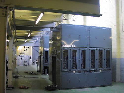
Traction Rectifiers in Queensland Road Sub-station, Northern City Line.
Control of circuit breakers
The four high speed circuit breakers in the TPH at Poole Street and the two high speed circuit breakers at Queensland Road and the two high speed circuit breakers at Finsbury Circus are controlled from local Slave Relay Units. In each case, the final interface to the high speed circuit breaker from the Slave Relay Unit is a BR930 relay contact which opens to discharge the traction section. This contact operates a D2600 interface relay (produced by Signature Industries, formerly Clifford and Snell) within the high speed circuit breaker from a nominal 50 volt d.c. supply provided by the d.c. switchboard. The Slave Relay Units are controlled over telecommunications cable from the Tunnel Telephone Cubicle at Finsbury Park.
Tunnel Telephone/Signal Post Telephone Tunnel Wires
In tunnel sections of the system, a Tunnel Telephone system provideds traction discharge and voice communication between the driver and Signaller at Kings Cross. Traction trip and speech is provided over two bare copper alloy wires carried, one above the other, on pairs of porcelain insulators supported on metal brackets fixed to the tunnel wall. The insulators are generally provided every 6 metres along the tunnel so as to keep the wires about 115mm apart. The wires are positioned so as to be accessible by leaning from the driving cab window of a train. The tunnel wires are divided into 20 sections so as to provide each colour light running signal with a dedicated speech circuit to the Signaller.
Trainborne equipment
Portable tunnel telephones are mounted in the cabs of all EMU which work over the line. They incorporate DTMF (Dual Tone Multiple Frequency) calling to the signaller and a means of shorting the circuit so as to discharge the traction supply. Pressing and holding either yellow button automatically sends a short burst of DTMF tone, after which speech is possible. The duplicated pushbutton makes the handset suitable for left-handed and right-handed users. Pressing the red ‘ISOLATE’ button places a low resistance across the tunnel wires, in order to discharge the traction supply. Alternately, Traction current may be discharged by simply 'pinching' together the two tunnel wires.

Tunnel Telephone used by Drivers to discharge traction or talk to the Signaller.
Tunnel Telephone/Signal Post Telephone Equipment Cubicle, Finsbury Park
A 2-metre high enclosed equipment cubicle is provided in the Telecommunications Equipment Room at Finsbury Park, together with a battery-backed power supply providing nominal 24 volt d.c. for the Tunnel Telephone equipment.

Northern City Line Tunnel Telephone system: Equipment Cubicle at Finsbury Park Telecommunications Equipment Room.
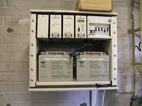
Northern City Line Tunnel Telephone system: Power supply at Finsbury Park Telecommunications Equipment Room.
The main telecommunications cables for the East Coast Main Line pass through a Distribution Frame in the Telecommunications Equipment Room, allowing simple cross-jumpering of the Northern City Line Tunnel Telephone circuits across to pairs leading to the controlling signal box at King's Cross.
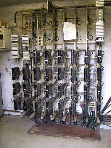
Northern City Line Tunnel Telephone system: Main Distribution Frame at Finsbury Park Telecommunications Equipment Room.
King's Cross Power Signal Box
The control of the Northern City Line was provided from King's Cross Power Signal Box (now planned for closure with control transferred to York Railway Operating Centre). At King's Cross, the Supervisor’s desk had a reset control panel which allowed York ECR to recharge the conductor rails of the Northern City Line. This was controlled from special Reset and Indication cards in the Telecommunications Equipment Room. Signal Post Telephone calls were processed by special SPT cards in the Telecommunications Equipment Room which detected the DTMF call tone and presented to call to Signallers on the main signalling console.
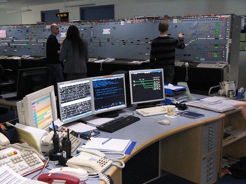
Supervisor's Desk & general view (Photo: Thales).
Related posts on other websites
Although the links worked at the time this post was published, changes made by that website's owner may 'break' the link.
Northern City Line (Wikipedia).
British Rail Class 313 (Wikipedia).
Great Northern and City Railway (Grace's Guide).
110 YEARS OF THE GREAT NORTHERN & CITY (The London Underground Railway Society).
Related posts on this website
London Underground - Traction Power Distribution.
Fourth Rail Electrification.
Electrification Telephone Systems for British Rail.
London Underground and Jan.
Rail Industry Information Day, 2018.
Related photograph albums
Where necessary, clicking on an image above will display an 'uncropped' view or, alternately, pictures may be selected, viewed or downloaded, in various sizes, from the albums listed:-
Northern City Line: 2-Nov-2006.
Kings Cross Power Box.
TTSystem for NCL: Installed System: 21-Oct-2009.
TT System for NCL: Equipment.
TT System for NCL: Testgear: 11-Jun-2009.
