skip to main |
skip to sidebar
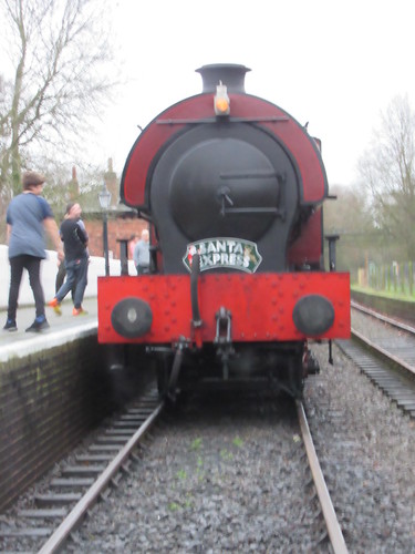
The Battlefield Line held 'Operation: Market Bosworth' - a '1940s Weekend' - on 17th and 18th September 2016.
A number of railways now run '1940s Weekend' events - I've been involved in the Peak Rail events since their inception in 2006. My report on the 2016 Peak Rail '1940s Weekend' (which didn't run quite as planned) is here and includes a list of all my earlier reports and pictures.
The first '1940s Weekend' at the Battlefield Line was in 2012 when I was driver on the diesel railcar which provided a shuttle service between Shackerstone and Market Bosworth in between steam-hauled service trains to Shenton. In 2013 the pattern was repeated and, again, I found myself driving the diesel railcar. I think I then missed a couple of years but was pleased to be rostered to drive the steam service on Saturday, 17th September 2016.
In 2016, the railway service for the weekend had been expanded. The normal 'Green Timetable' of five steam-operated return workings between Shackerstone-Market Bosworth-Shenton had been strengthened in the morning by an earlier additional round trip operated by the diesel railcar and in the evening by two 'Special' steam-operated round trips. All the steam trains were 5-coach, hauled by 'Austerity' 0-6-0ST locomotive 'Cumbria'.
Re-enactors, in both civilian and military dress of the period and a lookalike Winston Churchill created a 'Wartime' atmosphere.

Winston Churchill meets the public on Market Bosworth station.
There were numerous refreshment and trade stalls in the Goods Yard at Market Bosworth, together with extensive tented encampments for the 'combatants'. All types of military equipment and vehicles, including a replica Panzer III Tank, were on display. The Goods Shed itself hosted an array of stalls and a performance area for Ashby Little Big Band (who are also a regular attraction at the 1940s events at Peak Rail) and the vocalist Natalie Nightingale. On each day there was an exciting (and loud!) battle re-enactment. The programme of events was tied to the arrival of each train at Market Bosworth but, inevitably, delays to the service occurred during the day ("Don't you know there's a War on?").
The published programme was:-
11.50 a.m. Winston Churchill Address to the Nation
12.00 noon Ashby Little Big Band
12.50 p.m. Natalie Nightingale
1.30 p.m. Ashby Little Big Band
2.30 p.m. Battle re-enactment
3.15 p.m. Natalie Nightingale
3.50 p.m. Winston Churchill's "Victory in Europe" speech
4.00 p.m. Ashby Little Big Band
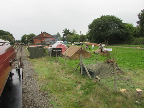
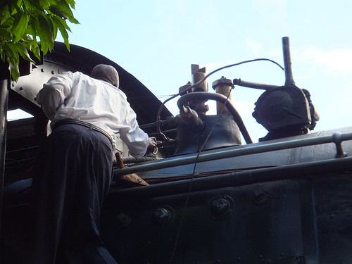
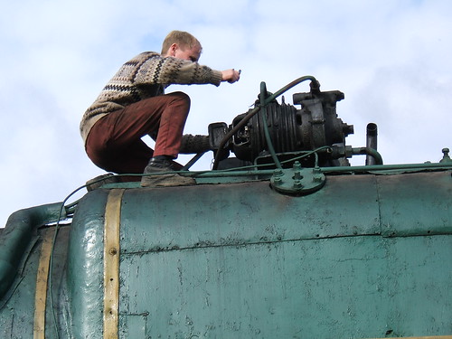
View from the footplate of 'Cumbria' approaching Market Bosworth, with part of the military encampment of the right and the large Goods Shed in the background.
During the day, the weather remained mild and it was gratifying to see so many people attending. Everybody I spoke to thought it a very successful day.
The event had faced formidable competition from 'Flying Scotsman' which made a public appearance at Tyseley Locomotive Works the same weekend, as advertised here. Back in the 1990s, I'd been one of the Instructor Drivers at Tyseley when 'Flying Scotsman' made a number of visits offering 'Flying Scotsman' driving experiences. There's a report on those visits here. I think the opportunity for members of the public to actually drive 'Flying Scotsman' is unlikely to recur in the future.
Our period-attired shopkeeper, Chris Simmons, accompanied by his wife Jo and son Charlie (temporarily an 'evacuee') displayed the appropriate 'Fighting Spirit' by displaying a defiant chalkboard announcing "NO NEED TO GO TO BIRMINGHAM - MEET THE FLYING SCOTSMAN HERE!".
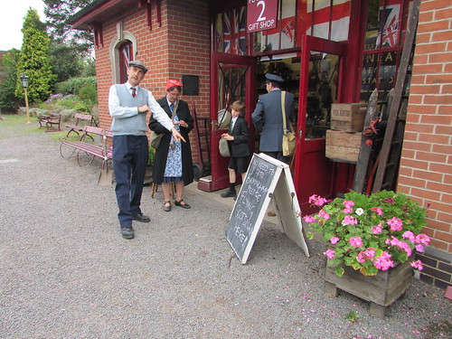
The Simmons family, outside Shackerstone station shop.
Chris's 'Flying Scotsman' was certainly green and carried the right nameplate!
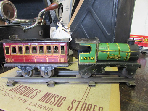
A tinplate 'Flying Scotsman' on display in Shackerstone station shop.
The two evening 'Specials' were well-patronised as re-enactors who had been occupied during the day took the opportunity to make a round trip of the train.
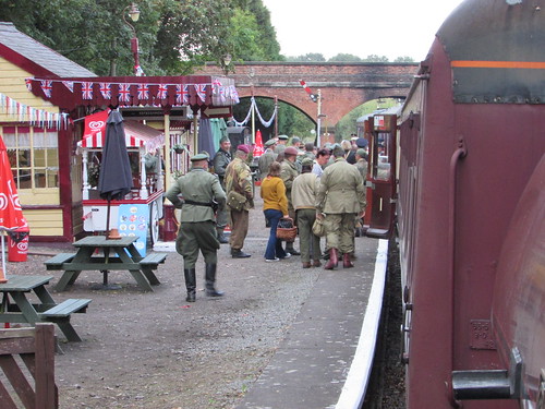
As dusk falls, re-enactors join the first 'Special' at Market Bosworth.
By the time the second evening 'Special' left Shackerstone, it was properly dark.
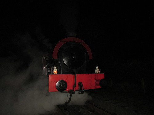
'Cumbria' ready to leave Shenton with the last service of the day.
Related Posts on this site
'Operation: Market Bosworth' - On the Footplate
Battlefield Line 1940s Weekend 2013.
Battlefield Line 1940s Weekend 2012.
My Pictures
Battlefield Line 1940s Weekend 2016.
[Link to ''Operation: Market Bosworth' - On the Footplate' added 8-Oct-2016]
In the post 'Flying Scotsman' at Birmingham Railway Museum, I briefly described my time with the locomotive at Tyseley between 1992 and 1995.
The commercial venture operated by the locomotive's then owners Sir William McAlpine and Pete Waterman was not successful and, on 23rd February 1996, the locomotive was sold, for 1.5 million pounds, to Tony Marchington, who then funded extensive repairs at Southall costing 1.45 million pounds.

'Flying Scotsman' at Southall.
When I'd last seen 'Flying Scotsman' in 1995, the locomotive was in its British Railways form as 60103. I may not have particularly liked the locomotive's appearance but at least it was historically correct. What emerged from Southall in 1999 was a confection combining 'Kylchap' exhaust and double chimney, LNER livery, the running number 4472, no smoke deflectors and air, rather than the original vacuum, brakes.
After a series of successful runs between King's Cross and York, which attracted widespread public interest, Tony Marchington "fulfilled a dream" of bringing the locomotive to his native Derbyshire. The locomotive appeared (on a low loader) at the 1999 Hartington Moor Steam Rally. Then, at the end of July 2000, the locomotive ran at Peak Rail during a 9-day 'Extravaganza'.
Although the initial hope had been to run service trains between Rowsley and Matlock, the locomotive's 22-ton axle load was not permitted over Bridge 35 (the bridge over the Derwent on the Darley Dale side of Matlock Riverside station). This resulted in southbound workings 'stopping short', north of the Derwent Bridge and, of course, there was no facility for a locomotive to 'run round' its train at this point. As a result, 'top and tail' working was adopted using a locomotive each end of the passenger train with 'Flying Scotsman', facing north, at the north end of the train and Peak Rail's 0-6-0T, facing south, at the south end of the train.
Since 'Flying Scotsman' had only air brakes, the vacuum-braked Peak Rail coaching stock could not be used and a suitable rake of dual-braked coaches was hired-in from West Coast Trains. Southbound workings would be vacuum braked, controlled from the 0-6-0T and northbound workings air braked, controlled from 'Flying Scotsman'. The dual-braked coaches duly arrived via the main-line connection at Matlock, hauled by one of Tyseley's main-line certified 'Pannier' tanks, which sat in the sidings at Darley Dale until it was time to take the dual-braked coaches back at the end of the event.
Because of its axle loading, 'Flying Scotsman' didn't have the option of arriving via the main line connection, but negotiated the less-than-ideal road system by low loader to reach Rowsley. The situation was complicated because of the crowds of sightseers lining the route, anxious to see this famous locomotive.
I was rostered on seven of the nine days of the 'Extravaganza', either as Driver or Conductor Driver on 'Flying Scotsman' or Driver on the 0-6-0T 'Austerity' attached to the other end of the train.
Whilst it was good to be re-united with the engine, I found the double-chimney, perched right at the front of the smokebox, looked rather unbalanced, an appearance not even relieved by the fitting of continental 'blinkers' carried as 60103. Later in her preservation career, the smoke deflectors were restored (presumably to help 'lift' the exhaust steam, rather than for aesthetic reasons). And, for me, no matter how much steaming might be improved by the 'Kylchap' exhaust and double chimney, these alterations jarred with the lined LNER livery and running number 4472. Whilst the way vacuum brakes were fitted to locomotives produced at Doncaster could present challenges (the design of the brake rigging sometimes allowed brake blocks to unexpectedly stick 'on'), vacuum brakes were historically part of the fundamental design so I was prejudiced against air brakes, particularly when the air was generated by a Polish steam-driven air compressor mounted between the frames. Although the compressor was not visually intrusive, it produced a very foreign-sounding slow, repetitive 'thump - chuck - thump - chuck'. Any form of conservation inevitably introduces compromises (I think 'Flying Scotsman', an A3 Class, has had an A4 boiler for years).I think I've commented before that, whilst I believe an owner has a right to turn out an engine in any style or livery he chooses, it doesn't mean I have to like it.
It was a very hectic period, with unprecedented crowds. Having been in charge of the recent repairs, Roland Kennington was there with others from Southall. I'd first met Roland Kennington back in 1992, when he came with 'Flying Scotsman' to Tyseley. In 2000 he did a number of driving turns at Peak Rail but, despite his experience, needed a Conductor Driver from Peak Rail on the footplate. I hadn't expected to like Tony Marchington, but found we got on quite well. Having spent all that money on the locomotive, it seemed rather sad that he was not even allowed to drive in traffic, except under supervision. I was flattered when he asked if I would teach him to drive but Roland decided that it would be more approriate if he carried out the instruction.
One day, an already-frail Alan Pegler was re-united with 'Flying Scotsman' and this was the only time I met him. On another occasion, I chatted to an elderly gentleman of, I think 98, who had been a Camden driver. I offered to show him the footplate of 'Scotsman' and he immediately agreed. His family were horrified, saying his mobility was far too bad to allow that. But I'd seen the gleam in his eye, so was unsurprised when he virtually skipped up the cab steps. He sat in the fireman's padded bucket seat and we chatted until it was time to leave.
Another day, Tony Marchington chartered the train for an evening meal with his large circle of friends and decided that his special guests would be favoured with a visit to the footplate. So we made unexpected use of Gresley's Corridor Tender, bringing guests to and from the footplate through the rather narrow passageway in the tender, as we made our majestic progress up and down the line. The contrast between the gaiety and bright lights in the restaurant car and the darkness and noise on the footplate was remarked upon by a number of guests. We weren't completely in the dark on the footplate because, after 1995, 'Flying Scotsman' had been fitted (or re-fitted) with electric lighting powered from a steam turbo-generator (there's a brief description of this type of equipment here.
Unfortunately, I don't have photographs of this period, but I did purchase commercial DVDs, one of which captured an interesting occurrence. I was firing the locomotive, prior to departure from Rowsley - not very demanding on such a gentle working provided you've experience of firing a wide firebox fitted with a 'Great Northern' 'Trap Door' firehole door (I've talked about the 'Trap Door' here). Suddenly, there's a muffled 'thump' and a tinkling. Jan looks up, very casually, to confirm that the fireman's side gauge glass has broken.
On a simple gauge glass, rupture of a glass would discharge water and steam through the broken ends, until the fireman was able to isolate both the steam cock and the water cock (protecting his hands whilst so doing with a jacket or sacking). However, 'Flying Scotsman' was fitted with an improved type of gauge glass incorporating an automatic shut-off ball valve as part of each isolating cock. These had operated correctly on breakage of the gauge glass so that I could manually isolate the cocks without difficulty. I then 'blew down' the driver's side gauge glass, to build some confidence that this glass was giving a true reading. A Great Western fireman would have been expected to replace a failed glass in a couple of minutes (Great Western engines normally had only one gauge glass, plus 'try cocks' as a backup). However, when I enquired about a spare gauge glass I was told we'd run with one gauge glass for the rest of the shift. So that's what we did.
After 'Flying Scotsman' completed its visit to Peak Rail, the story of this locomotive continued, not always happily. There's a potted history, up to 2013, here. When I can, I'll update that.
In the article The Railway at Night, I discussed the rather feeble headlamps carried by British steam trains, mentioning that many railways overseas, with unfenced routes, provided more substantial headlights. The most obvious use for electricity on steam locomotives was in replacing the various oil-powered lamps, particularly on railways where powerful headlights had always been used. An effective way of generating electricity from steam was a small turbine rotating a dynamo and a successful manufacturer in the U.K. was was J. Stone & Company, from Deptford, London.
Josiah Stone and others first established this engineering company in 1842 and there's more information on the history and activities of the firm here, in the indispensible Grace's Guide. The company became involved in the supply of electric lighting systems, dynamos and batteries for railway carriages world-wide as well as steam-powered generators. The railway product range further diversified before the company was taken over by Platt Brothers in 1958, trading as Stone-Platt Industries until closure in 1982.
Locomotive applications in Britain
British railway companies did not exactly fall over themselves to embrace locomotive steam turbo-generators but Thompson's B1s were fitted, together with some of the L.N.E.R. 'Pacifics'. Bullied's 'Pacifics' for the S.R. were similarly equipped, as were, I understand, the last two L.M.S. 'Coronation' class. In general, the installations provided electric headcode lamps at both ends in the normal positions, tail lamps (for running light engine) together with a gauge lamp and an overhead cab light (only used when the locomotive was stationary, to preserve the driver's 'night vision'). Sometimes, a lamp was provided under the cab to allow the fireman to check the overflow from the injectors to ensure he was not 'wasting water'.
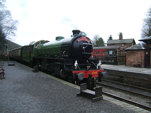
The pictures below show the arrangements on'B1' 'Mayflower'.
There are four white electric headlamps, plus one red tail lamp. Conventional lamp irons are also fitted to allow oil lamps to be carried where required.
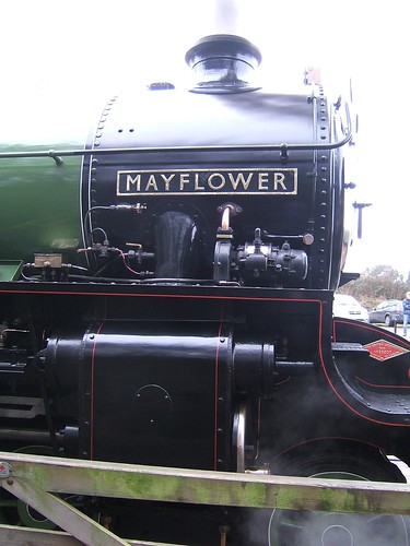
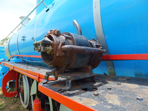
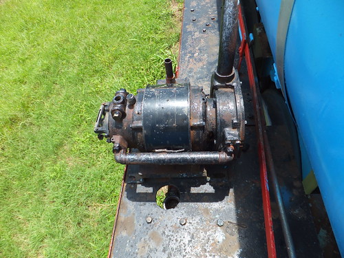
Mayflower's Stone's Steam Turbo Generator is neatly mounted adjacent to the smokebox, discharging its exhaust into the smokebox. All the electric wiring is run in steel conduit.

Detail of the white and red lamps in the middle of the buffer beam.
Locomotive applications Overseas
Railways overseas, with their interest in providing more powerful headlamps, were far more enthusiastic in adopting steam electric generators and there are pictures taken in various countries below.
United States of America
This Baldwin 2-8-0 (awaiting restoration), built in 1907, which I found during my visit to the State Railroad Museum, Boulder City in 2008, represents typical American practice. There's a little more about this exhibit here.
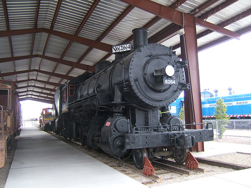
6264: The generator is on top of the firebox, the headlamp incorporates diagonal 'sidelights' displaying the locomotive number and wiring is carried in fixed or flexible conduit.
During WWII, America supplied locomotives to a number of countries and many of these had steam electric generators
Zambia
The following pictures show British-built locomotives for Africa now preserved as static exhibits in Livingstone Railway Museum, Zambia, as described here
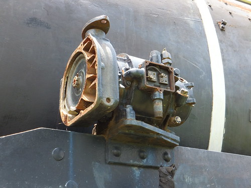
Locomotive running number 1126, showing part-dismantled steam turbine electric generator on fireman's side foot-framing (Sharp Stewart 4862 of 1902).
Another view of the steam turbine electric generator on No. 1126, showing rating plate 'Stone's Turbo Generator (Patented) No. 2461, 500 Watts, J. Stone & Co. Ltd, Deptford, London' (the company became limited in 1904).
Locomotive running number 70, built Neilson Reid, showing the electric headlamp and, mounted immediately behind, the steam turbine electric generator.
20th class No. 708 built by Beyer Peacock, works no. 7693 of 1954, showing part-dismantled steam turbine electric generator.
I also saw this type of equipment still in use when I enjoyed a footplate trip on the steam-hauled dining train, the 'Royal Livingstone Express', operated by the Victoria Falls Steam Railway, as described here.
The driver adjusts the cock supplying steam to the generator on the right, a J. Stone & Company Ltd product. The thin copper pipe is the steam supply, the vertical tube is the exhaust and the horizontal conduit is the electrical output (which changes into a pair of dangling wires leading to the cab!).
Ukraine, Mongolia & Russia
Russian-designed steam locomotives use electricity to work head lights and tail lights, illuminate the cab and the important water gauges. Electricity also powers the radio equipment used for train control. My visit to Ukraine in 2005 to drive preserved steam on the main line is described starting here. In 2012, my visit to Mongolia and Russia (described here) found a number of similarly-equipped Russian-designed locomotives in museums or 'plinthed' at stations.
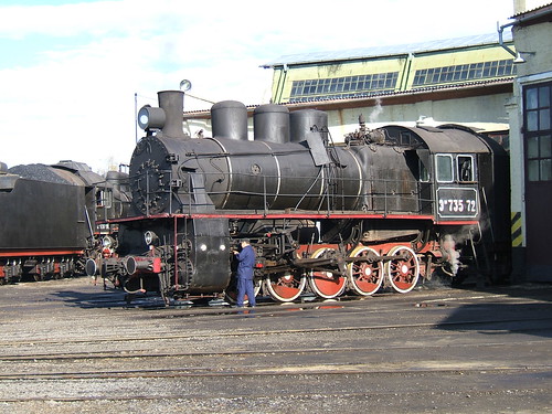
Em 735-72 appears to have two genenerators on the top of the firebox, one either side of the chime whistle.
Even this 0-4-0 tank B2137 has a generator on the top of the firebox, with its steam exhaust pipe pointed upwards.
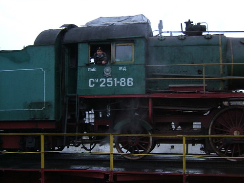
Su 251-86 showing the steam generator atop the firebox.
Attempted repairs to the turbo-generator on preserved Su 251-86 at Chernivtsi Motive Power Depot.
Class 'L' 2-10-0 freight locomotive L3535 at Chernivtsi Motive Power Depot showing the electric illumination of the dual boiler pressure gauge.
Poland
On my trip to Poland in 2003 (described here) I discovered that Polish steam locomotives usually showed three electric head lamps, as shown below.

Pt47-65 at Zybasyn, showing the three electric head lamps customarily carried.
Top view of Pt47-65. Note the air horn on cab roof and exhaust from steam turbine generator, which can be seen on the foot-framing, just ahead of the cab.
Other countries
I've found similar arrangements in a number of other countries, but they are not detailed here.
Beyond Illumination
Electricity, of course, has other potential applications on a steam locomotive beyond electric lighting. The use to power radio equipment in some countries has already been mentioned.
In the UK, The Automatic Train Control (ATC) introduced by the Great Western, followed by the Hudd system developed for use on the London, Tilbury and Southend Section of the L.M.S. were battery powered. The Hudd system was, after further work, adopted as the British Railways Automatic Warning System (AWS) with its distinctive heavy-duty battery box and came into widespread use before the demise of steam in the UK.
Electric speedometers on steam locomotives, where a generator rotated by a coupled wheel feeds a suitably-calibrated voltmeter, were also common on express locomotive classes.
Today, preserved steam locomotives running on the main line must not only be provided with 'Classic' AWS, but must have full Train Protection & Warning System (TPWS) capability, combining AWS with overspeed and train stop features, together with an On Train Monitoring Recorder (OTMR) - the railway equivalent of an aircraft's 'Black Box'.
Related picture albums
'Mayflower'.
Nevada State Railroad Museum, Boulder City.
Livingstone Railway Museum, Zambia.
Victoria Falls Steam Railway, Livingstone, Zambia.
Ukraine Steam.
Polish Railways (PKP).
A railway works largely on the principle of "See and be Seen". In the daytime, a driver can see where he is and observe the signals. People on or about the running lines, provided they keep a lookout, are aware of approaching trains and can ensure they are in a place of safety. But at night, it's not so simple. On roads, we're now accustomed to widespread artificial street lighting supplemented by powerful headlights on vehicles. On the early railways, this was not the case. Various schemes were tried out using a flaming fire brazier at the front of the train (to warn of the trains approach) or at the rear (to act as a warning to a following train).
The Tail Lamp
The red Tail Lamp established itself as the 'last line of defence' for a slow-moving or stopped train to warn a following train. Considerable effort was put into making these oil lamps reliable and visible. Although the actual flame used was small, when combined with glass 'bull-eye' or, more recently, cast glass 'Fresnel' lens, in good conditions these could be seen from a considerable distance. There's a little more in the post MIC - Lamps.
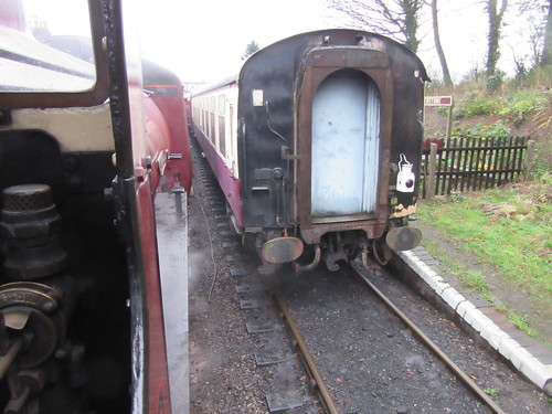 View of rear of passenger train on arrival at Shackerstone on the Battlefield Line, viewed from a second train waiting to leave. The oil tail lamp confirms that the train has arrived complete.
Traditional Railways in Britain
In general, railways in Britain are fenced so, in theory, members of the public are excluded and there is less need for a bright headlight to warn people of the approach of the train. Although locomotives typically carried white headcode lamps which could be set in different patterns, these were provided purely so that signalmen could confirm the type of train approaching both by day and at night.
'Cumbria' (with headlamp lit) ready to return from Shenton. The single lamp near the chimney indicates an 'Ordinary Passenger Train'
At night, drivers faced blackness ahead, scanning the dark for the all-important signal indications. To preserve the driver's all-important 'night vision' there was little illumination on a steam locomotive footplate. It was normally restricted to a 'Gauge Lamp' which used rape seed oil (which is less flammable than paraffin) so that the fireman could confirm the boiler water level in the Gauge Glasses. Some locomotives were provided with a shield a shield between the firedoors and the driver's position to protect the driver from the glare when the firedoors were opened during firing. The driver had to orient himself by careful observation of his surroundings. Sound became important and drivers would know where they were from the sounds made by bridges, cuttings and other lineside features.
As railways developed, so did railway signalling to regulate the movement of trains. This evolution is briefly described here. Fixed signals were initially semaphore, as described in another signalling post here. At night, the indication was made visible by movement of the signal arm placing different coloured filters in front of the light from a small oil lamp, as described in the post Railway Signalling in Britain: Part 4 - Semaphore Signal Aspects by Night.
To enhance the visibility of signal indications further, methods of electrically illuminating signals were developed, resulting in Colour Light Signals where the semaphore arm (and moving parts) are eliminated and, by day and by night, the indication is given by various combinations of powerful coloured and white lights.
Modern Railways in Britain
Whilst less important routes in Britain still retain semaphore signalling, colour light signals are becoming universal. More recently, colour light signals using filamentary lamps are being replaced by multi-element Light Emitting Diode designs providing enhanced light outputs with greater efficiency. Most preserved railways (where speeds are generally moderate) continue to use mainly semaphore signals.
On the national railway network, oil tail lamps have been replaced by portable flashing battery-operated lamps using Light Emitting Diodes or, on multiple unit stock, built-in electric lights. With few signal boxes to observe the headcode of an approaching train, electric 'marker lights' are now provided at the front, together with one high-intensity white light to provide a warning to staff working on or about the line. This high-intensity light does give the driver some forward visibility at night but it mainly serves to improve the sighting of the various types of lineside reflective signs provided for the driver's guidance.
Railways overseas
Many overseas countries had unfenced railways, increasing the chances of members of the public being on the tracks at night so there was more need for bright headlights to act as a warning. I found a summary of the American experience in 'Presentation Magazine' at The History of the Railway Locomotive Headlamp.
Electrical Systems on Steam Locomotives
The use of electricity could increase the brightness of locomotive headlamps and offered more convenience over oil lamps which needed filling and trimming regularly. Some electric generators were introduced on steam locomotives in Britain but their use was far more widespread overseas, as described in the post Electrical Systems on Steam Locomotives.
[Reference to post 'Electrical Systems on Steam Locomotives' added: 14-Sep-2016]
Click on any picture or drawing below for a larger, uncropped view.
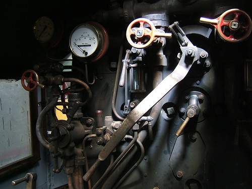
In the article Locomotive Regulators (part 1) I discussed early regulators for steam locomotives and the very common two-port slide valve designs.
Whatever the precise design, this steam valve, which allows the engine to move, is called the 'Regulator' or sometimes the 'Throttle'. It's a proportionate valve - the more the operating handle is moved, the more steam flows to the cylinders. The valve itself is usually mounted within the boiler, where the steam is generated, as part of the 'steam dome'. The steam dome is the highest part of the boiler to minimise the pick-up of droplets of water from the mass of water below. Alternately, the regulator valve could be situated in the smokebox - the Great Western developed a very successful smokebox regulator of the horizontal slide valve type.
Conventionally, the regulator is controlled by rotating the regulator rod passing through the boiler backhead so as to operate the regulator mechanism in the boiler. This rotation is achieved by pulling on what may be a fairly long handle attached to the end of the regulator rod on the footplate to give the driver sufficient leverage to be able to adjust the regulator valve against the pressure of steam inside the boiler. In the most common designs, the driver moves this handle in an arc. In 'Lion', for instance, it's fully closed with the handle at about 2 o'clock and fully open at about 10 o'clock. Different classes of engine have different detailed regulator design and sweep through different arcs. For instance, most Great Western Engines have a regulator handle which moves from 5 o'clock to 1 o'clock. I was surprised to discover that the regulator on the marvellous Great Eastern '1500' class moves from 4 o'clock to 8 o'clock ('underarm'). Left hand drive engines have mirror-image regulator arcs.
The steam pressure on the valves in the slide valve pattern helps to stop steam leaking past the valve but, as boiler pressures became higher and locomotives became more powerful, regulators could be quite hard to open or shut, sometimes needing the combined efforts of driver and fireman so some designs have two handles attached to one regulator rod - one, conventionally, pointing towards the driver's position, the second pointing to the fireman's side. The effort required, particularly to open a regulator onto 'Main Valve' (also called 'Second valve') can be quite demanding.
On smaller locomotives, a second regulator handle may be fitted because, during shunting, the driver may have a better view from the 'wrong' side of the cab and the second handle allows the driver better control of the movement. Some designs also provided a duplicate brake valve on the 'wrong' side. Where small shunting locomotives were used in private sidings, 'single manning' was often resorted to so the distinction between 'Driver' and 'Fireman' was lost.
Not all regulator handles would stay where they were put, but would tend to 'creep'. To counter this, enginemen might carry a wedge which could be placed between the regulator handle and the quadrant to prevent unwanted movement. In India, I found a chain used to prevent the regulator from creeping closed.
Many Overseas, L.N.E.R., S.R. and British Rail 'Standard' locomotives had 'pull-out' regulator handles moving fore-and-aft where the handle is pulled towards the driver to admit steam to the cylinders often, but not invariably, working a 'balanced' regulator. On Overseas locomotives with this feature, there is often a ratchet mechanism, released by a trigger handle, to prevent the regulator from 'creeping' from the set position, but I've not seen this feature on British-made engines used in Britain.
Plug and Butterfly designs (mentioned in part 1) were, as far as I know, only used in the early years of locomotive design so now we have just slide valve, balanced and multi-valve (as used, for instance, on LMS 'Pacifics') types to consider.
Vertical Dome-mounted Slide-valve regulators
The arrangement of this type of regulator was shown in part 1 of this post and the picture below shows a vertical slide valve regulator on the sectioned locomotive 'Pender' at the Museum of Science and Industry in Manchester (MOSI), where I was a Volunteer for many years (resulting in a number of posts about MOSI here).

There are also a couple of pictures in the post The Best Laid Schemes ... which describes the failure of a regulator linkage.
Horizontal Dome-mounted Slide-valve regulators
As boilers became larger, vertical dome-mounted regulator valves could be hard to fit within the loading gauge. At the L.M.S. Stanier, with his Swindon background, originally adopted the Great Western approach of a slide-valve regulator mounted in the smokebox but, with the introduction of his 4-6-0s, he produced a dome-mounted horizontal slide valve regulator which most enginemen liked.
In the diagram below, 14 is the port face forming the start of the main stam pipe which has with three ports, covered by the main valve 8 when the regulator is shut. The main valve 8 is provided with two narrow openings 6 and 7 which are normally open to steam and two main ports 11a and 12a each divided into three which are closed to steam until the main valve 8 is displaced from the closed position. The pilot valve 5, when closed, obstructs the narrow openings 6 and 7 in the main valve but does not impede steam through main ports 11a and 12a. To open the regulator, the regulator rod is rotated, pivoting the actuating rod 3 which moves the actuating rod 4, forcing the pilot valve to move, successively opening narrow openings 6 and 7 so that steam flows from the dome to the main steam pipe. The actuating slot in the top of the main valve is wide, so that the actuating rod 4 does not start to move the main valve until pilot ports 6 and 7 are fully open, then main ports 11a and 12a allowing increased steam flow.

Balanced 'Double-beat' regulators
To reduce the effort required by the driver in making adjustments to the regulator, the balanced, or 'double-beat' regulator was introduced. An early form was produced by Ramsbottom. Later, Lockyer patented a version used by the North Eastern Railway. In the form used by Gresley,the balanced regulator allows steam on both sides of a lifting bobbin-shaped valve so reducing effort required to adjust the valve. The horizontal regulator rod (pushing from the right of the diagram below) operates the bell crank so as to lift the valve from its seating, allowing steam to flow from the dome to the main steam pipe.

'Flying Scotsman' has this type of valve. My post 'Flying Scotsman' has a contemporary drawing here. If you select one of the the larger sizes of the drawing, you can see how the balanced regulator is fitted into the boiler. The LNER (always masters of self-publicity) described the regulator as giving 'finger tip control'. Whenever I've driven 'Flying Scotsman', I've found the regulator provides nothing that could be remotely described as giving 'finger tip control'. There's a brief description of my early meetings with the locomotive here. The only 'A4' Pacific I've driven ('Sir Nigel Gresley), whilst otherwise a superb machine, was just as bad as far as ease-of-operation of the regulator goes.
Multiple Valve regulators
As far as I know, these were only used on large, superheated locomotives. A number of satisfactory designs of superheater were developed but The Superheater Company Limited achieved widespread success, marketing products under its 'MeLeSco' trade mark worldwide. It also developed a multiple valve regulator, which I think was used by the L.M.S. and L.N.E.R. and achieved worldwide sales well in excess of 40,000 units! The design (shown in the diagram below) is based on a modified superheater header casting where the forward part of the casting is divided into three transverse chambers, one above the other. The top chamber is connected to the superheated steam output from the superheater. The middle chamber connects to the main steam pipes, delivering superheated steam to the cylinder steam chest. The bottom chamber is a balancing chamber. A series of fairly small valves control the passage of steam from the top to middle chamber. These valves are progressively opened and closed by cams on a rotating camshaft operated by the regulator handle. Initial movement of the regulator handle first opens a pilot valve which admits steam to the balancing chamber so that further movement of the regulator requires little effort to open, in turn, each of the main valves.

I drove Princess Margaret Rose on one of her visits to Tyseley years ago but don't recall how I liked the regulator action using a multiple valve regulator - my impression was of a magnificent (and big) engine.
A Regulator Gallery
I like the Great Western regulators which I've experienced on a number of classes. The regulator on 5080 'Defiant' really was 'finger-tip' - I'm sad that she's now on static display at Buckinghamshire Railway Centre.

Standard Great Western regulator handle on 2-8-0 '3803'. Note the round counterweight.
Stanier regulator handle on 2-8-0 '8624'. Note the sprung stop bearing on the quadrant, preventing 'creep'.
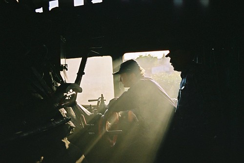
In 1992, I had an opportunity to drive a Class 'WP' on the main line in India. There's a brief description of this trip buried in the post here.
Class 'WP' in India: I'm holding the regulator handle through force of habit - at this point, we've attached a chain from the roof to the handle to prevent the regulator from closing itself.
The only American-built class I've driven is an 'S160' (with a ratcheted regulator handle) at Peak Rail. On tugging open the regulator, there was a distinct delay, followed by a 'clang' from the dome (which, at the time, I commented "sounded like a dustbin lid being rattled"), then steam flowed.
 The spartan lines of an 'S160' (Photo: lner.info)
In 2003, I was fortunate in driving three different locomotive classes at Wolsztyn in Poland. There's a post called, simply, Poland with a link to pictures.
 Pm36-2 'Piekna Helena' en route to Lesno (the 'arty' shot). The regulator arc is from about 1 o'clock to 11 o'clock.
In 2005, I had the opportunity to drive three Russian-designed classes in Ukraine - the first of a series of posts is at Ukraine 2005 with links to pictures.
Russian-designed Su 251-86 in Ukraine showing boiler backhead with short regulator handle (with ratchet) rotating the regulator rod via a link.
Events of Thursday, 28th April, 2016
In the post on the previous day's activities, here I described how the smaller fishing vessels clustered overnight around Bar Wel Island. On Thursday morning, by the time we were enjoying our accustomed sustaining breakfast on deck, many of these boats had either already left for a day's fishing or were preparing to go out. But quite a few of the odd-looking squid fishing vessels remained, probably having returned after a night's fishing.
Squid fishing is usually carried out at night, assisted by numerous powerful electric lamps (mercury vapour Lamps, producing a rather eerie blue light). These lamps are arrayed along a series of improbably long booms extended horizontally out from the hull. No two vessels seem alike in the details of the rigging of the booms, although they generally appeared to be converted from fairly elderly 'trawler' types, similar in layout to the one we'd visited earlier in our cruise (described here), having a stayed derrick mast (either wood or steel) on the foredeck with a single boom to unload the catch and load supplies. Usually, the booms were made of what appeared to be a series of substantial steel tubes joined together with couplers to produce the required length but I also saw trusses made from smaller tubes with welded cross-bracing. The booms require a complex series of guy ropes to support them and these ropes terminate on the derrick mast on the foredeck and on a smaller stern derrick or on the superstructure.

The fishing fleet at Ba Wel: A stern view shows the length of the steel lighting booms, which are supported by guying from a steel derrick mast on the foredeck and a smaller steel mast at the stern.
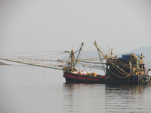
The fishing fleet at Ba Wel: This Squid Fisher has a wooden Derrick mast and both tubular and truss booms to support the lamps.
Squid are an important food source in many parts of the world. There's an introduction to the creature here. There's a little about fishing for shortfin squid here. The lighting system attracts the nocturnal squid to the fishing vessel, gathering in the unlit area beneath the hull, waiting for prey. A series of lines, carrying metal 'lures', are lowered into the water and 'jigged' up and down, encouraging the squid to attack the lures, in which they become entangled. Periodically, the lines are raised to recover the catch. Modern Squid Fishing vessels are equipped with Jigging Manchines which lower the lines, 'jig' them, raise the lines and invert the lures so that the squid fall off automatically (as outlined here) but I saw no evidence of this type of equipment in use at Ba Wel.
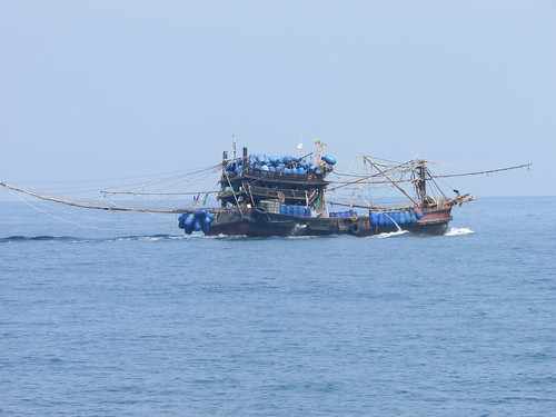
A Squid fishing vessel under way (pictured on a previous day).

A rather ungainly-looking squid fishing vessel at Ba Wel Island (pictured on a previous day). Six men can be seen, plus, I assume, one in the wheelhouse.
After enjoying the usual sustaining breakfast, we made our return to Kawthaung under engine power: our final opportunity to enjoy simply being at sea. After a few days around the undeveloped islands, the sheer size and the bustle around Kawthaung came as something of a shock.

Arriving back at Kawthaung.
'Meta IV' anchored in the harbour and all the guests said 'Goodbye' to the crew. We piled into the dinghy with our luggage and Aung transferred us to Myoma Jetty. My Australian friends and I were booked on the afternoon flight back to Yangon, so, once Aung had retrieved the car, he drove us towards the airport. It took me a while to adjust to the level of road traffic, much of it motor cycle taxis of a distinctive design, apparently quite modern but with the driver on the right of the machine, more suited to driving on the left of the road (as Burma did, until the sudden change to driving on the right mandated in 1970).

Around Kawthaung.
As our flight did not leave for a few hours, Aung had arranged for us to relax in the luxury of the Victoria Cliff Hotel & Resort. After a light lunch in the restaurant which offered stunning views of the Andaman Sea, I relaxed in the shade by the swimming pool. It was very hot, and I couldn't muster the energy for anything requiring more exertion.
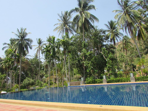
Around Kawthaung: The swimming pool at the Victoria Cliff Hotel & Resort.
Aung picked us up in plenty of time for the final road journey to Kawthaung Airport, where we left Aung. I'm afraid that, after the comfort at the Victoria Cliff, Kawthaung Airport was rather basic but, eventually, our flight arrived and I boarded with some relief.
Kawthaung-Dawei-Yangon by air: Boarding the Apex flight to Yangon
On the way back to Yangon, we made the scheduled brief stop at Dawei, arriving at the Domestic Terminal at Mingalardon on time. My checked bag appeared fairly quickly, my transport was waiting and I was soon returned to the Doctor's house, where I was staying the night. The next morning I had another early start, as I was to fly north with the Doctor to Bagan.
Related posts
Next post in this series.
All my posts on my trip to Myanmar in 2016 can be found here.
My pictures
If necessary, pictures in this article can be viewed uncropped by clicking on the image. To view in other resolutions or download, select from the albums below:-
The Fishing Fleet at Ba Wel.
Sailing back to Kawthaung.
Around Kawthaung.
Kawthaung - Dawei - Yangon by air.
All my pictures on this trip.
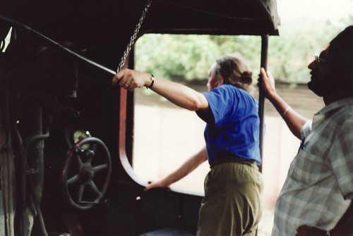
Every year, the Old Locomotive Committee (OLCO) organises a get-together, called 'Lionsmeet' for modellers of the 'Lion' locomotive (and similar models of designs from the early days of railways). On Saturday 27th August 2016, I attended the Old Locomotive Committee annual 'Lionsmeet' event which was held at the Nottingham Society of Model and Experimental Engineers Limited (Nottingham SMEE) site at Ruddington, occupying part of what was formerly called Nottingham Transport Heritage Centre.
Getting there
I travelled by train from Wolverhampton and there's a post describing the journey here. After doing a quick survey of the station and its architecture, I took a taxi from Nottingham Station. As we drove through the city, it started to rain and then the driver had some difficulty locating the destination because the post code which had been advised was not the best one and left us, tantalisingly, a few hundred yards short of my goal. Fortunately, I spotted a brown 'tourist sign' in the distance and was able to direct the local driver the rest of the way! I afterwards discovered that a more helpful post code would have been NG11 6JS. We'd arrived at the large site, apparently originally an industrial complex. Part of the area had been redeveloped as modern commercial property whilst the remainder now provided accommodation not only for Nottingham SMEE, a preserved bus group and a model railway group but also serves as headquarters for the standard gauge-preserved railway Great Central Railway - Nottingham. Just inside the main gate I spotted a large sign directing visitors to the miniature railway so a few minutes trudge through the rain past the Bus Museum took me to my destination.
The Event
I found Andrew and David Neish in the Clubroom, sheltering from the rain and enjoying a warm drink. Soon, I'd also been provided with a beverage and the rain stopped, so things were looking far more promising. Activities transferred to the Steaming Bays as other attendees started to arrive by car.
Nottingham SMEE was first established in 1929 and has been on the present site for around 25 years. The original accommodation is a converted and extended industrial building providing a well-equipped workshop (including multiple Bridgeport manual milling machines), mess, kitchen, toilets and a spacious Clubroom with modern Audio-Visual facilities.
Nottingham SMEE: General view of the well-equipped workshop.
There is substantial purpose-built accommodation for 7.25" gauge locomotives and rolling stock. In one building, I admired a handsome 7.25" gauge model of a '2P' which was undergoing a boiler test.
Lionsmeet 2016, Nottingham: 40602 undergoing a hydraulic test. Boiler Inspector John Lopez underneath checking the firebox foundation ring.
There are custom-built covered Steaming Bays for 3.5" and 5" gauges.
Lionsmeet 2016, Nottingham SMEE: The Steaming Bays have three parallel raised tracks in a handsome building, topped by magnificent smoke louvres.
The original running track is 2270 feet in length, elevated, dumb-bell shaped, offering dual-gauge (3.5"/5") track using aluminium rails. There is now also an extensive 7.25" ground level system, roughly oval-shaped laid outside the elevated track. The 7.25" track also has a triangular junction serving a branch leading to a terminus called Parkgate nearer the site entrance .
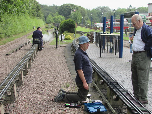
As at recent 'Lionsmeet' events, the format was 'free running', that is no competitive running, using only the elevated track since no 7.25" gauge models steamed this year. As the 'early steamers' (notably Andrew and David Neish with David's familiar 'Lion' and Adrian Banks with his 'Thunderbolt') moved their models onto the elevated running track, I obtained permission to walk around the circuit to familiarise myself with the facilities.
The elevated track is signalled with automatic 3-aspect colour-light signals for clockwise running, so I took this direction for my walk, starting at Little Ruddington station.

Nottingham SMEE: Little Ruddington Station with (L-R) elevated track, 7.25" gauge station, exhibits outside Bus Museum.
Immediately on leaving the station, there is the expected traverser to move locomotives from the steaming bays towards the running circuit but this involves crossing the ground-level 7.25" track. This hazard is protected by a proper level crossing with four gates with gate stops, power-operated from the adjacent signal box, Little Ruddington West, and interlocked with signals on the ground level track.
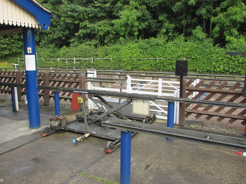
Traverser serving the steaming bays pictured next to the level crossing.
The height of the Traverser can be adjusted as necessary. The Traverser mounts a battery to power the height adjustment and the battery can be re-charged from a power lead mounted on one of the steaming bay roof supporting columns. This traverser does not deliver locomotives directly to the running line but to an intermediate siding.
Next, I passed Little Ruddington West signal box which has a beautifully-engineered 50-lever frame in miniature which controls the power-operated points and signals on the ground-level track. This frame has a miniature level crossing gate wheel to control the level crossing gates and this requires around 12 turns in the appropriate direction before movement of the gates takes place!
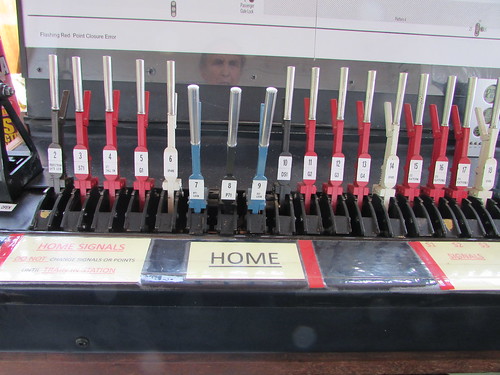
Nottingham SMEE: Part of the miniature lever frame in Little Ruddington West signal box. Just visible left is the supporting frame carrying the level crossing gate wheel.
Just outside the signal box, a second traverser not only transfers locomotives from the intermediate siding to the elevated running line but also moves carriages between the carriage shed and the running line.
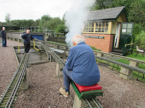
David Neish moving his 'Lion' onto the running line using the long traverser which also transfers carriages from the brick carriage shed visible in the background to the running line.
After this second traverser, the line then passes through a wooded area as it negotiates one end of the 'dumb bell'. The curvature and, on my visit, the dampness combined with 'leaves in the line' made this a tricky area for drivers.
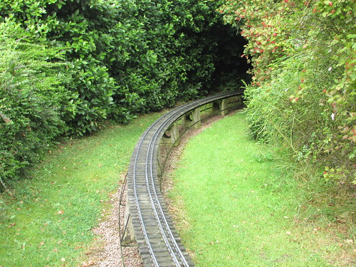
Nottingham SMEE: The 'wooded area'.
Emerging from the wooded area, the elevated track passes a garden area which includes an extensive 'Gauge 1' layout on an raised baseboard. The elevated track then runs to the rear of the signal box and, on a long 'back straight', passes the station area.
A Nottingham SMEE member undertakes permanent way maintenance (or prayer?) as Adrian Banks heads for the tunnel on 'Thunderbolt'.
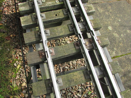
Nottingham SMEE: The rail joints in the 3.5" and 5" gauge track are 'lapped' to allow expansion of the aluminium rail.
The elevated track next passes through the first 'bore' of a '2-bore' tunnel before reversing direction on the second 'dumb bell'. After traversing the second 'bore' of the tunnel the line arrives back at the station area.

Nottingham SMEE: The tunnel section, looking towards the station.
A couple of diesel-outline petrol-engined models - a 2-car Diesel Multiple Unit and a 'Class 20' - gave rides to the public on the 7.25" gauge track.
Sophie, a lady engineer who is a member of Nottingham SMEE, ran her 'Lion' on the elevated track. Her 'Lion' is one of three built some years ago by Robert Clark, who was a respected member of Nottingham SMEE. Having sold one of the three (probably for display), the builder died when still quite young. The brother of the deceased gifted the second 'Lion' to a close friend of the builder. The remaining 'Lion' was offered to members of Nottingham SMEE and it was acquired by Sophie, who already had a number of loco building projects to her credit.

Lionsmeet 2016, Nottingham: Sophie and her friend.
By this time, Jon Swindlehurst with his 'Lion' and a fifth 'Lion' were being prepared for demonstration running.
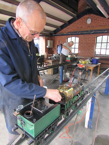
Lionsmeet 2016, Nottingham: Jon Swindlehurst prepares his 'Lion' with another 'Lion' being steamed in the background.
I took one ride behind Jon (forgetting, despite years of being 'Official Observer' or 'Dynamometrix' during 'Lionsmeet' contests, what a 'fire thrower' his willing model can be - a real "Nor' Wessie" engine!) Demonstration running was suspended when a wide range of sandwiches was revealed for the visitors but after a leisurely break, some models continued to steam whilst other attendees either continued to chat or examined the part-built models on display.
John Hawley showed his part-built 7.25" gauge 'Lion' and the assembled driving wheelset for his 5" gauge 'Lion'. I foolishly originally described the as for his 7.25" 'Lion', forgetting that John had displayed his 5" 'Lion', started by Michael Lee, at the Guildford 'Lionsmeet' in 2015 (described here), when the driving wheelset was a 'kit of parts'.
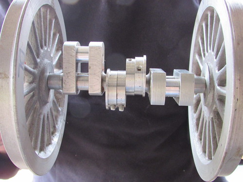 Lionsmeet 2016, Nottingham: Part-assembled driving wheelset for John Hawley's 5" gauge 'Lion'.
Jon Swindlehurst showed progress on his remarkable 7.25" gauge 'Modified Lion', with Stephenson Link Motion and Balanced Slide Valves. Fabrications have replaced what would normally be castings.
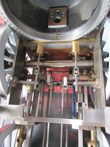 Lionsmeet 2016, Nottingham: Jon Swindlehurst's 'Modified Lion' - view from above showing expansions links and valve rods.
OLCO member David Wilson displayed a modified design of regulator suitable for 'Lion' models. Chairman John Brandrick told me that it is based on the screw-down version described by Martin Evans for 'Simplex' and that Jon Swindlehurst's 'Lion' employs a similar design, not unlike that in the full-size Lion. There's a little about the regulators employed on full-size locomotives, including 'Lion', here.
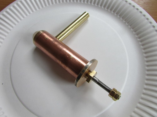 Lionsmeet 2016, Nottingham: An OLCO Member displayed this modified design of regulator.
The rain had held off during most of the day the day and there were some periods of bright sunshine allowing everybody to enjoy the event.
Related posts on other sites
Lion & The Old Locomotive Committee
The Official Website for Lion & The Old Locomotive Committee.
The Nottingham Society of Model and Experimental Engineers Ltd.
Great Central Railway - Nottingham.
Related posts on this site
By Rail to Nottingham.
All my Old Locomotive Committee posts.
My pictures
Lionsmeet 2016.
All my Old Locomotive Committee pictures.
[Corrected following correspondence with J. Brandrick and J. Hawley: 9-Oct-2016]


