I'm passed to drive on the diesel multiple units at the Battlefield Line but not passed on any of the various other diesel locomotives. About 30 years ago, when I was a regular volunteer at Birmingham Railway Museum, I was passed out by their Traction Inpector (whose 'day job' was Traction Inspector on British Rail) to drive their '08' shunter and visiting preserved Class 47 'Ixion' which was used for driving experience courses. I also did a bit of shunting with a visiting Class 31. I've always been a fan of the Class 08, a rugged and reliable machine, and my brief 'User Notes' (with a link to training notes prepared by British Rail, York) are here. Under supervision, I've since had 'hands-on' on a number of other diesel locomotives at various locations with mechanical or electric transmission (and shunting locomotives with hydraulic transmission) but never a Class 20, so I accepted the offer of a training session with Graeme as instructor driver.
Origins of the Class 20
Following Nationalisation of the railways in 1948, British Railways initially committed to building a range of 'Standard' designs of steam locomotives. By the time the last was built (Class '9F' 'Evening Star'), the 'Standard' stud numbered 999 locomotives. But difficulties in recruiting staff to operate and maintain these locomotives, combined with problems in the mining industry extracting the coal to fuel the fleet induced politicians to embrace a change of direction and replace steam with diesel and electric traction. This transition is briefly introduced in the post The Modernisation of British Railways. A series of 'Pilot Scheme' diesel locomotives were ordered from various manufacturers in four power ranges increasing from Type 1 (a general-purpose freight type) through Type 2 and 3 up to the express passenger Type 4.
English Electric were chosen for the Type 1 design. They had been building rugged diesel engines for marine and other applications for some time and their 'straight six cylinder' had given good service in the LMS diesel shunters. In 1947 they introduced a 'Vee' type of engine with pairs of cylinders set 45 degrees apart driving a common crankshaft. The 16-cylinder version (16SVT) of this engine had been used by Ivatt in the well-known LMS prototype main-line diesel electrics 10000 and 10001 and also in the Southern Railway's candidates emerging in the British Rail era as 10201, 10202 and, finally, the uprated 10203. This proven engine series was adopted for the 1000 h.p. (750 kW) Type 1 locomotive using their 8SVT Mark II diesel engine.
8 - number of cylindersThe engine crankshaft was bolted directly to an English Electric 319-3C main generator with an output of 1070 Amps at 600 volts d.c. An English Electric 911-2B auxiliary generator 'overhung' on the main generator, producing 110 volts d.c. for the compressor, exhauster, traction motor blowers and battery charging.
S - supercharged (actually turbocharged)
V - Vee form
T - adapted for railway use
Mark II (4-valve cylinder head)

Auxiliary generator, main generator, 8SVT diesel engine forming power unit of Class 20 locomotive.
The locomotive underframe was two longitudinal, parallel box sections (each formed from two channel sections plated-over top and bottom to produce a box section), with welded 'transoms' forming a rigid frame. Part of the two underframe box sections were sealed off to provide the modest fuel capacity of 390 gallons and two of the 'transoms' also served as balance pipes between the two tank sections.
The power unit was mounted on the underframe together with auxiliaries (including engine-driven fan, oil pump and water pump and electrically-driven air compressor, vacuum exhauster, traction motor blowers, fuel pump), all protected by a long 'bonnet' or hood , inset to give a 'running board' each side. A series of hinged access doors along each side allowed staff ready access to the equipment. At what was regarded as the rear of the locomotive, a driving cab was provided, with duplicated driving 'desks'
The assembled locomotive was mounted on two 4-wheel bogies using welded-frame equalising-beam design with helical springs and 3 foot 9 inch diameter wheels. Overall length was 46 feet 9.25 inches and weight 73 tons.
The four axles were each fitted with an English Electric 526/8D (/5D on first 50 off) nose-hung 6-pole series-wound, force-ventilated d.c. motor rated at 600 Amps, 300 volts d.c. driving through a single reduction gear.
The locomotives were arranged so that up to three units could be interconnected for multiple working from the leading cab using Electro-Pneumatic (E.P.) controls, allowing heavier trains to be worked.

Class 20 locomotive General Layout
Click for larger view
With the English Electric pedigree, the design proved reliable and did all that was asked of it so between 1957 and 1968 a total of 228 locomotives were built, originally numbered in the D8000 series but renumbered with the '20' prefix when the 'TOPS' system (see description on Wikipedia) was introduced in 1971.
The improved cab environment proved popular with some drivers and the good view of the line when running 'cab leading' was appreciated. The more restricted view ahead through the smaller window looking along the 'bonnet' when 'nose leading', although not that dissimilar from that on a steam locomotive, was not favoured and it became commonplace for the locomotives to 'hunt in pairs', coupled nose-to-nose, allowing drivers to adopt the preferred 'cab-leading' driving method in both directions. The class gained an enthusiast following, who dubbed the class 'Choppers', leading to a number of units having been preserved. Perhaps more signicantly, examples still remain in commercial service in a number of countries. I think there are still occasional passenger railtours using the class 20. I wrote about one such tour I witnessed (but didn't travel on) in the 2015 post here.
Class 20 at the Battlefield Line
Graeme W. was booked driver with Jamie W. as Secondman. We were using the locomotive with final running number 20 110 which was stabled down the North End at Shackerstone, currently painted green and carrying its original number D8110.

Class 20 stabled at the North End at Shackerstone.
We all clambered over the locomotive as Graeme demonstrated the pre-start checks.

L: Air Compressor (with Traction Motor Blower behind) R: Vacuum Exhauster (Class 20 at the Battlefield Line)

View of 8SVT engine: Class 20 at the Battlefield Line

Main Generator (Class 20 at the Battlefield Line)
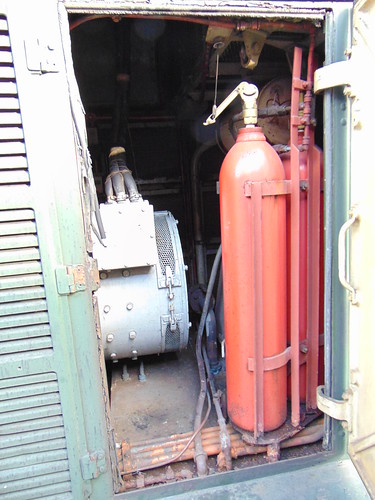
Overhung auxiliary generator and fire extinguishing installation (Class 20 at the Battlefield Line)
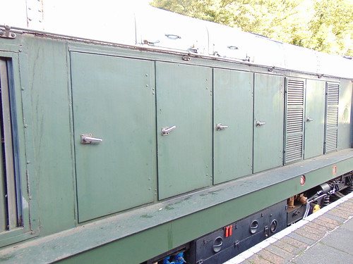
Left side of locomotive showing 'bonnet'. Note handrail above engine/equipment access doors and underframe-mounted battery box/battery isolating switch painted black (Class 20 at the Battlefield Line)
Graeme started the diesel engine. Electric start is provided by connecting the 110 volt battery to an extra winding on the main generator so spinning the engine crankshaft. We waited for the compressor to produce sufficient control air pressure and then Graeme shunted to our 6-coach train waiting in platform 2. Jamie 'hooked-on' ready for our first round trip to Shenton. Graeme drove the first trip then, for the rest of the day, I shared the driving with Graeme and (on trip 3) Adrian.

Class 20 110 arriving back at Shackerstone on 30-Oct-2021
The two driving desks are positioned for left-hand drive. Layout is standard with brake controls on the left, power and reverser controls on the right, with an inclined instrument panel facing the driver. Fairly crude swivel seats are provided fixed to the floor at each driving position.
Light engine movements are controlled by the 'straight' Air Brake but, when working vacuum-braked stock, control is via the separate Vacuum Brake Application Valve which is intended to apply the air brakes on the locomotive proportionally to the train vacuum but I need more training to properly get the 'feel' of this combination, tending to underbrake or, more often, overbrake and then having difficulty "blowing off" the vacuum to keep rolling.
The Driver's Surveillance Device (DSD) or 'deadmans' is in the form of an inclined, hinged metal plate on the floor which must be kept depressed when in motion or otherwise, after a short delay, all brakes are applied. The back wall of the cab has a handwheel for applying a 'parking brake', requiring numerous turns to apply or release the brake through a chain drive.
I did notice that, having left Shenton 'nose-leading' and mounted Shenton Bank, advancing the power controller to produce line speed in the cutting did produce a 'business-like' exhaust noise. At the end of the service schedule, I was able to leave the locomotive with Graeme as it was being used again for an evening special. All-in-all, a good day.

Class 20 at the Battlefield Line showing cab and Number 2 Bogie, with Jan in earnest conversation.
Related Posts on this site
The Modernisation of British Railways.
Class 08 User Manual.
Related Post on other sites
English Electric diesel engines.
Book references
[1] 'BR Class 20 Diesels' Michael Oakley (Bradford Barton) ISBN 0 85153 419 8.
[2] 'Description and Fault Finding Instructions for Drivers' (English Electric/BRB Book FS227)
[3] 'Diesel Traction Manual For Enginemen' (BRB 1962)
My pictures
Class 20 at the Battlefield Line
Depending on the display device, the right hand edge of pictures may not display. To see an uncropped image, click on the picture. Alternately, you can find the image by following the 'My pictures' link and display or download the image in various resolutions.
