The first tunnel under the River Mersey was a railway tunnel. The authorising act of 1866 was for the Mersey Pneumatic Railway but investors were chary of such a novel concept and progress was not made until James Brunlees took over in 1870. He changed the name to the Mersey Railway, envisaging a conventional underground railway operated by steam locomotives. With gradients as severe as 1 in 27, it was still a challenging line.
Work started in 1879 and continued for a number of years. During the tunnel construction phase, 'Scientific American' published an upbeat review of progress and, through the work of Project Gutenberg, this contemporary account appears below.
Beyer Peacock supplied massive 0-6-4T condensing locomotives to operate the Mersey Railway and the line finally opened in 1886, but conditions in the tunnel for passengers (let alone enginemen) were atrocious. The railway was soon in financial difficulties and receivers were appointed in 1887. The financial situation was improved in 1888 by the connection of the tunnel lines to the Wirral Railway, producing a proper suburban network extending to Wallasey and New Brighton. However, despite the provision of steam driven fans (the largest 40 feet in diameter!) intended to keep the tunnels clear, steam traction only lasted until 1903 when, to the relief of everyone concerned, electric traction took over. The three books in the 'References' section below have further information about the Mersey Railway.NO. 384, NEW YORK, MAY 12, 1883
THE MERSEY RAILWAY TUNNEL.
The work of connecting Liverpool with Birkenhead by means of a railway tunnel is now an almost certain success. It is probable that the entire cost of the tunnel works will amount to about half a million sterling. The first step was taken about three years ago, when shafts were sunk simultaneously on both sides of the Mersey. The engineers intrusted with the plans were Messrs. Brunlees & Fox, and they have now as their resident representative Mr. A.H. Irvine, C.E. The contractor for the entire work is Mr. John Waddell, and his lieutenant in charge at both sides of the river is Mr. James Prentice. The post of mechanical engineer at the works is filled by Mr. George Ginty. Under these chiefs, a small army of nearly 700 workmen are now employed night and day at both sides of the river in carrying out the tunnel to completion. On the Birkenhead side, the landward excavations have reached a point immediately under Hamilton Square, where Mr. John Laird's statue is placed, and here there will be an underground station, the last before crossing the river, the length of which will be about 400 feet, with up and down platforms. Riverward on the Cheshire side, the excavators have tunneled to a point considerably beyond the line of the Woodside Stage; while the Lancashire portion of the subterranean work now extends to St. George's Church, at the top of Lord street, on the one side, and Merseyward to upward of 90 feet beyond the quay wall, and nearly to the deepest part of the river.
When completed, the total length of the tunnel will be three miles one furlong, the distance from wall to wall at each side of the Mersey being about three-quarters of a mile. The underground terminus will be about Church street and Waterloo place, in the immediate neighborhood of the Central Station, and the tunnel will proceed from thence, in an almost direct line, under Lord street and James street; while on the south side of the river it will be constructed from a junction at Union street between the London and Northwestern and Great Western Railways, under Chamberlain street, Green lane, the Gas Works, Borough road, across the Haymarket and Hamilton street, and Hamilton square.
Drainage headings, not of the same size of bore as the part of the railway tunnel which will be in actual use, but indispensable as a means of enabling the railway to be worked, will act as reservoirs into which the water from the main tunnel will be drained and run off to both sides of the Mersey, where gigantic pumps of great power and draught will bring the accumulating water to the surface of the earth, from whence it will be run off into the river. The excavations of these drainage headings at the present time extend about one hundred yards beyond the main tunnel works at each side of the river. The drainage shafts are sunk to a depth of 180 feet, and are below the lowest point of the tunnel, which is drained into them. Each drainage shaft is supplied with two pumping sets, consisting of four pumps, viz., two of 20 in. diameter, and two of 30 in. diameter. These pumps are capable of discharging from the Liverpool shafts 6,100 gallons per minute, and from the Birkenhead 5,040 gallons per minute; and as these pumps will be required for the permanent draining of the tunnel, they are constructed in the most solid and substantial manner. They are worked by compound engines made by Hathorn, Davey & Co., of Leeds, and are supplied with six steel boilers by Daniel Adamson & Co., of Dukinfield, near Manchester.
In addition to the above, there is in course of construction still more powerful pumps of 40 in. diameter, which will provide against contingencies, and prevent delay in case of a breakdown such as occurred lately on the Liverpool side of the works. The nature of the rock is the new red sandstone, of a solid and compact character, favorable for tunneling, and yielding only a moderate quantity of water. The engineers have been enabled to arrange the levels to give a minimum thickness of 25 ft. and an average thickness of 30 ft. above the crown of the tunnel.
Barges are now employed in the river for the purpose of ascertaining the depth of the water, and the nature of the bottom of the river. It is satisfactory to find that the rock on the Liverpool side, as the heading is advanced under the river, contains less and less water, and this the engineers are inclined to attribute to the thick bed of stiff bowlder clay which overlies the rock on this side, which acts as a kind of "overcoat" to the "under garments." The depth of the water in one part of the river is found to be about 72 ft.; in the middle about 90 ft.; and as there is an intermediate depth of rock of about 27 ft., the distance is upward of 100 ft. from the surface of low water to the top of the tunnel.
It is expected that the work will shortly be pushed forward at a much greater speed than has hitherto been the case, for in place of the miner's pick and shovel, which advanced at the rate of about ten yards per week, a machine known as the Beaumont boring machine will be brought into requisition in the course of a day or two, and it is expected to carry on the work at the rate of fifty yards per week, so that this year it may be possible to walk through the drainage heading from Liverpool to Birkenhead. The main tunnel works now in progress will probably be completed and trains running in the course of 18 months or two years.
The workmen are taken down the shaft by which the debris is hoisted, ten feet in diameter, and when the visitor arrives at the bottom he finds himself in quite a bright light, thanks to the Hammond electric light, worked by the Brush machine, which is now in use in the tunnel on both sides of the river. The depth of the pumping shaft is 170 feet, and the shaft communicates directly with the drainage heading. This circular heading now has been advanced about 737 yards. The heading is 7 feet in diameter, and the amount of it under the river is upward of 200 yards on each side. The main tunnel, which is 26 feet wide and 21 feet high, has also made considerable progress at both the Liverpool and Birkenhead ends. From the Liverpool side the tunnel now extends over 430 yards, and from the opposite shore about 590 yards. This includes the underground stations, each of which is 400 feet long, 51 feet wide, and 32 feet high. Although the main tunnel has not made quite the same progress between the shafts as the drainage heading, it is only about 100 yards behind it. When completed, the tunnel will be about a mile in length from shaft to shaft. In the course of the excavations which have been so far carried out, about 70 cubic yards of rock have been turned out for every yard forward.
Ten horses are employed on the Birkenhead side for drawing wagons loaded with debris to the shaft, which, on being hoisted, is tipped into the carts and taken for deposit to various places, some of which are about three miles distant. The tunnel is lined throughout with very solid brickwork, some of which is, 18 inches thick (composed of two layers of blue and two of red brick), and toward the river this brickwork is increased to a thickness of six rings of bricks--three blue and three red. A layer of Portland cement of considerable thickness also gives increased stability to the brick lining and other portions of the tunnel, and the whole of the flooring will be bricked. There are about 22 yards of brickwork in every yard forward. The work of excavation up to the present time has been done by blasting (tonite being employed for this purpose), and by the use of the pick and shovel. At every 45 ft. on alternate sides niches of 18 in. depth are placed for the safety of platelayers. The form of the tunnel is semicircular, the arch having a 13 ft. radius, the side walls a 25 ft. radius, and the base a 40 ft. radius.
Fortunately not a single life has up to the present time been lost in carrying out the exceedingly elaborate and gigantic work, and this immunity from accident is largely owing to the care and skill which are manifested by the heads of the various departments. The Mersey Tunnel scheme may now be looked upon as an accomplished work, and there is little doubt its value as a commercial medium will be speedily and fully appreciated upon completion.

The picture below shows one of the condensing locomotives, clarifying the operation of the condensing facility. A large slide valve, fixed to the side of the smokebox, was provided in the exhaust from each cylinder. A control rod from the footplate either diverted the exhaust into the smokebox (when working above-ground) or into the side tank (when in the tunnel). An inverted U-shaped pipe linked the two side tanks and vented air (or uncondensed steam). Note that, in the present 'Cecil Raikes', each side tank has a separate vent.
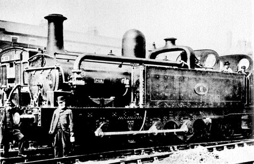 Locomotive No. 6 'Fox' in service (Photo: 'The Pictorial Encyclopedia of Railways' by Hamilton Ellis, published by Paul Hamlyn, 1968).
Following electrification, the redundant steam locomotives were sold off. In 1904 locomotive No. 5, 'Cecil Raikes', was sold to Shipley Colliery in Derbyshire in 1904, where it worked for the next fifty years. Then followed some years in storage at Derby Locomotive Works before British Railways Board presented the locomotive to National Museums Liverpool in 1965.
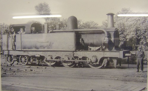 'Cecil Raikes' in colliery service at Shipley.
Since the Museums had no suitable way of displaying the locomotive, it was placed on loan and displayed at Southport Steam Centre ('Steamport') which occupied the disused British Railways steam shed at Southport.
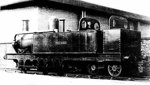 'Cecil Raikes' at the Southport Steam Centre (Photo: Southport Steam Centre).
This is where I first saw 'Cecil Raikes' in the 1980s. The 'Steamport' operation subsequently relocated to Preston as The Ribble Steam Railway and 'Cecil Raikes' returned to Liverpool Museums and was again placed in store.
I next saw the locomotive in 2010, as I described in my post here. The museum staff allowed me to take a series of pictures.
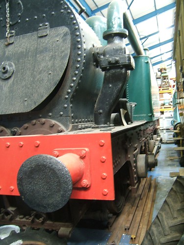
There was little space to frame the shot but this perhaps gives an idea of of the size of this powerful 0-6-4T.
Articles on other websites
See Wikipedia article here.
See also Liverpool's Historic Rail Tunnels
Book References
[1] 'The Line Beneath The Liners: A hundred years of Mersey Railway sights and sounds' by John W. Gahan, published by Countyvise (ISBN 0 907768 40 7 and Avon AngliA Publications (0 905466 57 8).
[2] 'An Illustrated History of Liverpool's Railways' by Paul Anderson, published Irwell Press (ISBN 1-871608-68-6).
[3] 'British Railway History - An outline from the Accession of William IV to the Nationalisation of Railways, 1877-1947' by Hamilton Ellis, published by George Allen and Unwin, 1959.
My pictures
Profile - 'Cecil Raikes'.
[Revised 10-Oct-2013 - picture of 'Fox' added]
