skip to main |
skip to sidebar
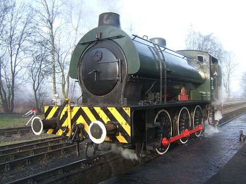
'Sapper' on the outside pit at Rowsley being prepared for the day's running.
In this post, I concentrate on the Driver's duties in oiling and examining the locomotive. Preparation of 'Sapper' is generally similar to preparation of other 'Austerity' tank locomotives, such as Peak Rail's 'Royal Pioneer' (currently posing as '68013') described a few years ago in the post here. The most noticeable difference in 'Sapper' is the use of two 'Wakefield' Mechanical Lubricators to ensure a reliable supply of oil to important parts of the locomotive.
The person oiling the locomotive should always carry a clean rag or woven 'Wiper' to remove any spilt or excess oil. Oil where it shouldn't be will become transferred to the next person to visit that area. In places like the foot framing, spilt oil is likely to be hazardous as it can cause slips. Any dust or ash around will tend to mix with the oil and produce an unsightly and hard to remove coating.
Mechanical Lubricator for Cylinder Oil
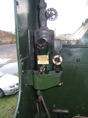
A 'Wakefield' Mechanical Lubricator for Compound Cylinder Oil ('Steam Oil') is mounted on the left foot-framing just behind the smokebox. The box-like casting (which is filled with the appropriate grade of clean oil daily or as necessary) has a hinged lid clamped shut to exclude dust and ash. Immersed in the oil are small oil pumps driven from a shaft which passes through a gland to the circular ratchet mechanism marked 'WAKEFIELD' visible in the picture above.
The ratchet mechanism is oscillated back and forth by suitable connections to a reciprocating or rotating part of the motion. In the case of 'Sapper', the Mechanical Lubricators are operated from small eccentric cranks mounted on the crankpins of the leading axle. As the mechanism is oscillated, an internal pawl rotates the shaft through a small angle on each oscillation. Thus, whenever the locomotive is in motion, the pumps are delivering oil through the elbows and copper oil lines visible on the left of the Lubricator. To make sure that the oil lines are 'primed' with oil before leaving the shed, the 'U' shaped bar connected to the shaft is manually rotated a number of times.
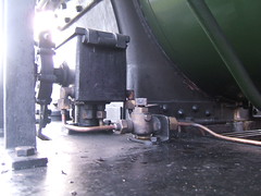
This view shows the 'Wakefield' Mechanical Lubricator viewed from the rear of the locomotive. Cylinder oil has quite a high viscosity (usually at least SAE 680) and it can become very viscous in cold weather. The copper pipe on the right is a steam feed to the cock mounted on the foot-framing just behind the lubricator. When the square-headed cock is unscrewed, steam is passed through a heating pipe to warm the oil.
Sight-Feed Lubricator for Cylinder Oil
As built, 'Sapper' will have been provided with just a Sight Feed Lubricator. Where a Sight-Feed, or similar, lubricator is fitted, this is usually mounted on the fireman's side so that makes it more logical for the fireman to look after the 'steam' oil. 'Sapper' has a 'Eureka' Type 'G' single-feed sight-feed lubricator on the Fireman's side of the cab. As I've commented elsewhere, the Great Western Railway regarded sight-feed lubricators as so vital to the running of the engine that the lubricator was always fitted in front of the driver and was the drivers responsibility. To find out more about the G.W.R. approach see the post Summer Saturday with a '2884' and, in particular, the last section titled 'Sight Feed Lubricator'. Normally, once a mechanical lubricator is fitted to a locomotive, no sight feed lubricator would be provided but 'Sapper' has both types and both types are used.
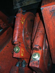
Mechanical Lubricator for Axlebox Oil
A second 'Wakefield' Mechanical Lubricator for Axlebox Oil (often called 'Motion Oil') is mounted on the right foot-framing just behind the smokebox. Construction is similar to the Mechanical Lubricator for Cylinder Oil but the casting is larger to accommodate additional oil lines (in this case six, one per axlebox. In this case, the window showing the oil level faces outwards and can easily be checked during preparation (there is a check window on the Mechanical Lubricator for Cylinder Oil but it faces the centreline of the engine).
Oiling Round
Of course, checking the oil level in the Mechanical Lubricators and priming them is only one task. There are six oil cups on the coupling rods to be filled and two holes to place oil on the Gradient Pins.
There is an oil box on the framing either side behind the smokebox delivering oil to each piston gland and each valve gland. There are two oil boxes (left and right) on the frame stretcher which serves as a motion plate. Each oil box has four oil lines delivering oil to the front and rear of the upper slide bars associated with each cylinder. There are oil cups closed with corks on the two little ends and two more on the valve rods where they pass through the motion plate. I find I can best reach these last points by lying on the foot framing and reaching into the motion but each person has to find a method which suits their build, reach and fitness. On 'Sapper' there are also two oil boxes (left and right) fitted further back just above the frames. Each has three oil lines feeding oil to the hornguides. The right hand one is best reached from outside, but the left one I tend to defer until I'm between the frames, described next.
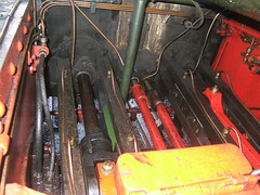
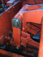
The next bit I find the hardest. Starting on the foot framing on the fireman's (left) side, I lower myself in between the frames behind the weighshaft and ahead of the crank axle, standing on the brake rigging facing the rear of the engine. How easy this is depends on the 'angle' that the motion is sitting at. In the picture, the right crank is near front dead centre and the left crank is near the top. With luck, the oil cups closed with corks on the two big ends and the four eccentrics can be dealt with, hopefully without dropping a cork into the pit.
Then, I try to turn round so as to face the front of the engine. If the left hand crank is anywhere near the top, I usually end up sitting on the connecting rod. The picture shows the four lifting links suspended from the 'arms' on the weighshaft. Pairs of lifting links are attached to the left and right curved, slotted expansion links. The top of the each expansion link is connected to the associated foward eccentric rod, the bottom of each expansion link is attached to the associated reverse eccentric rod. The picture gives a fair idea of the rather poor access. There are a number of oil holes to be dealt with - at the top and bottom of the lifting links, at the top and bottom of the expansion links and on each dieblock (to provide lubrication to the machined faces of the curved slot in the expansion link). Those are the major oiling points but, as described in the earlier post, there are other points which may benefit from the judicious application of oil.
On locomotives fitted with a steam brake, there is usually a small oiler near the boiler backhead, positioned in the steam line to the steam brake cylinder. 'Sapper' has a cylindrical oiler, normally dealt with by the Fireman by filling it with Cylinder Oil during preparation. This oil is allowed to find its way to the brake cylinder, with the aim of avoiding a 'stuck piston'.
Examination
As important as careful attention to oiling is the 'Daily Exam'. Every part of the construction should be studied during preparation, looking for anything unexpected - something becoming detached, unusual wear, missing split pins or nuts, anything broken, loose or showing signs of cracking (particularly on the springing), anything out of alignment. Time spent in examination at this stage reduces the chance of embarrassment later due to a failure. A pit greatly assists a proper examination, allowing wheels, axleboxes, springs and spring hangers to be closely examined. The picture shows the view forward from just in front of the firebox. The connecting rods are left and right and the two reverse eccentric rods are in the middle, closest to the camera with the expansion links behind. The motion plate is in the background.
Photographs
Larger versions of all the pictures in this article (plus other pictures of the locomotive) can be found in the set below:-
'Sapper' Austerity Tank Locomotive