skip to main |
skip to sidebar
The garden at Brewood Hall has a number of trees which, of course, require periodic inspection and attention.
The first post on this topic is Oak Tree Pruning at Brewood Hall.
A second post Brewood Hall Tree Maintenance reported on later work.
Dave Evans, the forester who looks after the trees and the garden at Brewood Hall arranged for further necessary work to be carried out on 25th July 2018. He brought in Dave Nagington (who has worked at Brewood Hall in the past) with Buster, Graham and Darren.
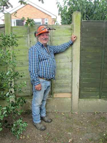
Brewood Hall Tree Maintenance: Dave Nagington, 25th July 2018.
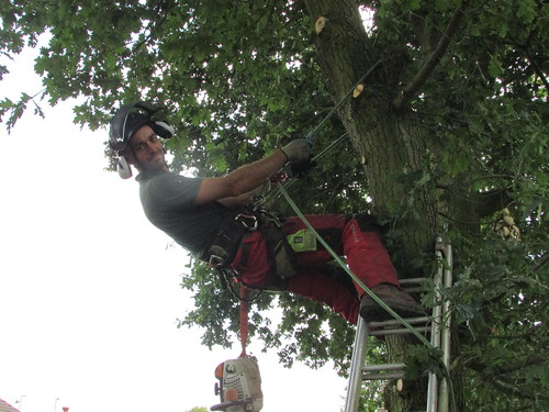
Brewood Hall Tree Maintenance: Darren, 25th July 2018.
Sadly, two dangerous trees near the boundary fencing had to be felled.

Brewood Hall Tree Maintenance: Damaged acacia prior to felling, 23rd July 2018.

Brewood Hall Tree Maintenance: Remains of second dangerous tree after felling, 25th July 2018.
A number of oak, a weeping ash and various other trees were expertly pruned and the removed branches dealt with on site by a high-capacity woodchipper (a self-propelled 'Timberwolf' TW190TF1R).
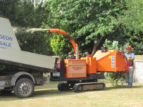
Brewood Hall Tree Maintenance: Graham 'feeding' the self-propelled 'Timberwolf' TW190TF1R, 25th July 2018.
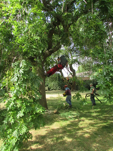
Brewood Hall Tree Maintenance: Darren in the Weeping Ash, with Graham and Dave, 25th July 2018.
The work included pruning branches overhanging Sandy Lane.
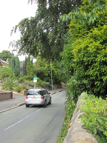
Brewood Hall Tree Maintenance: Sandy Lane before pruning, 25th July 2018.
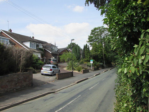
Brewood Hall Tree Maintenance: Sandy Lane after pruning, 25th July 2018.
I was very pleased with the results of this maintenance work.
Related posts on this website
Oak Tree Pruning at Brewood Hall.
Brewood Hall Tree Maintenance.
My Pictures
Where necessary, clicking on an image above will display an 'uncropped' view or, alternately, pictures from may be selected, viewed or downloaded, in various sizes, from the album below:-
More Brewood Hall Tree Maintenance.
The Battlefield Line held a Steam Gala on the weekend of 13th and 14th October, 2018. Three locomotives were in steam - 'Light Prairie' 5542 (which had performed excellent work on the steam services throughout 2018) 'Pannier' 6412 (expected to remain until Christmas 2018) and veteran 6-coupled saddletank 813.
In the post Battlefield Line Steam Gala 2018 (Part 1), I described the first day of the Gala, when I was on 813. This post describes the second day of the Gala.
Events of Sunday, 14th October 2018
On Sunday, I was rostered on 5542, sharing the driving with Adrian L. The Sunday timetable was similar to the first day of the Gala, with 813 allocated to the same services as on Saturday. But, for variety, the roles of 6412 and 5542 were reversed with 5542 working the eight 'Auto trains' (one of which would traverse the complete line to Shenton) and, finally, (having disposed of the 'auto-trailer') double-heading the 18:00 4-coach train to Shenton with 6412.
Adrian and our Cleaner, Stephen, had lit-up when I arrived and Adrian was already well-on with oiling round but I joined in to complete the work. Once 813 had gone 'off-shed' to work the 08:00 freight train, we were able to move the engine outside the shed and complete preparation before shunting to the DMU siding to pick up our 'Auto coach'.
Steam locomotives working auto-trains require modification to allow the regulator to be remotely controlled from the driving compartment of the Auto-coach when the locomotive is not leading. The Great Western Railway always used mechanical remote control of the regulator, but other methods were possible (like the Vacuum Controlled Regulator used by the L.M.S.). Two of the Great Western locomotives in use at the Steam Gala (5542 and 6412) were equipped for auto-train working so 'Pannier' 6412 had run with the auto-coach on Saturday (as described in Part 1) and 5542 carried out the diagram on Sunday.
Connecting to a passenger vehicle usually involves attaching and tightening the heavy screw coupling then wrestling the two vacuum hoses together and securing them with one or two pins (some people insist on two pins but all the old footplatemen I met were quite content with one). In the steam heating season, the steam heating hoses between locomotive and train also require connection. This process quickly becomes second-nature to trainees on turns where the locomotive has to run around the coaches at each end of the journey. There's a little more information about the screw coupling in the post The Role of the Shunter (2) and the complete process of coupling vehicles is outlined in the article On the Footplate (Part 2). With an 'Auto train', of course, the locomotive stays attached to the train throughout. However, there are three additional interconnections to be made between locomotive and train for Auto-working:-
Remote Regulator control
Remote Whistle control
Electric Bell
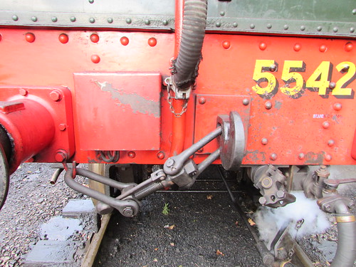
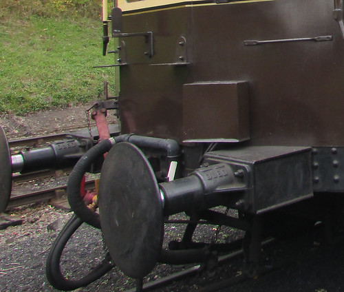
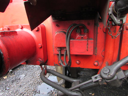
5542 rear bufferbeam. Note hinged cover over electric bell connector to right of buffer and remote regulator 'universal joint' underneath bufferbeam to right of drawhook.
Remote Regulator control
The Great Western used a purely mechanical method of remote regulator control. Because of the relative movement which must be allowed between the locomotive and auto-trailer, a push-pull movement of the remote regulator shaft connecting the locomotive to auto-coach cannot be used. Instead rotation of this remote regulator shaft is used to represent desired regulator opening. A supporting bracket underneath the buffer beam of a auto-fitted locomotive carries a substantial 'universal joint' with a square jaw to accept the sleeve of the auto-coach control shaft, which is pinned in place.
An auto train is normally formed with the rear of the locomotive attached to one or two trailing auto-coaches. However, it's possible to additionally attach one or two auto-coaches to the front of the locomotive as well so auto-fitted locomotives normally carry a 'universal joint' under both front and rear bufferbeams.
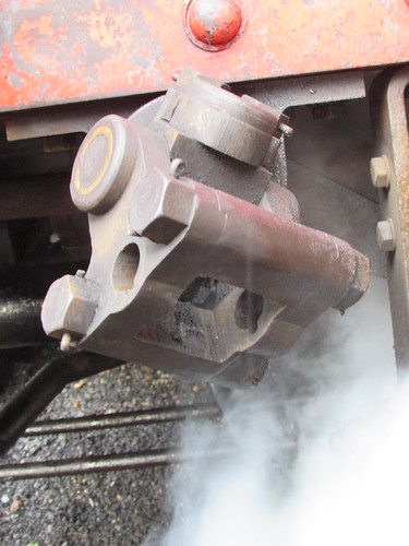
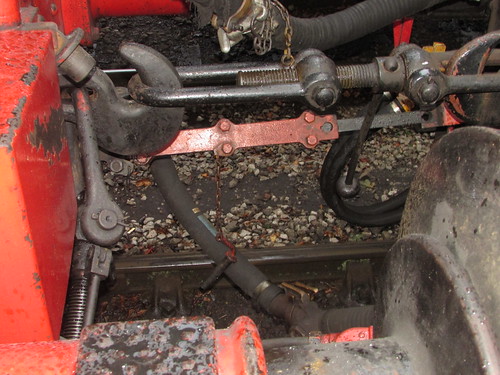
5542 rear bufferbeam showing remote regulator 'universal joint'. Note keyed holes for securing pin when the sleeve of the auto-coach control shaft is attached.
Each rotating 'universal joint' is connected via a system of rods and a crank to a vertical rod passing through the floor of the cab near the boiler backhead so that up and down movement of the vertical rod is converted into rotation of the 'universal joint'. The vertical rods terminate in a coupling, allowing either 'front' or 'rear' rod to be pinned to the hole in the specially-adapted regulator handle so that upwards movement of the rod opens the regulator and downwards movement closes the regulator.

5542: Front and rear remote regulator linkages. Required linkage is 'pinned' to the keyed hole visible in the regulator handle of the left.
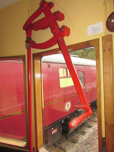
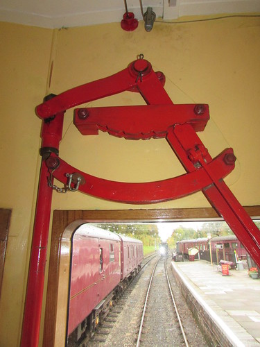
The auto-coach mounts a remote control regulator linkage with a 'universal joint' at the coach end allowing the linkage to be folded upwards diagonally and pinned to a stowing bracket on the non-driving end of the auto-trailer when not in use. The red-painted remote control regulator linkage cab be seen (not very clearly, I'm afraid) in the picture below.
W233 Auto-trailer non-driving end showing red-painted regulator remote control attached to the stowing bracket with pin and chain.
When in use, the remote control regulator linkage is released from the stowing bracket and lined-up with the square jaw of the 'universal joint' on the locomotive. The linkage comprises a square steel shaft sliding in a red-painted 'sleeve' which is extended to engage with the jaw of the 'universal joint' on the locomotive, to which it is secured by a pin and chain. When the train is in motion, relative movement between the locomotive and auto-trailer is accommodated by the square steel shaft sliding in the 'sleeve'.
W233 Hawksworth Auto-trailer attached to locomotive 5542, showing the red-painted sleeve of the remote control regulator linkage.
The glazed end wall in the driving compartment of the auto-trailer mounts a pivoted remote regulator handle operating from about 'five o'clock' (closed) to 'seven o'clock' (fully open) with a small latch engaging in a series of 'detents' in the regulator quadrant. Movement of the remote regulator produces up-and-down movement of a vertical round rod passing through the floor of the driving compartment. Beneath the floor of the auto-trailer a crank and a system of rods is converted into rotation of the remote control regulator linkage so as to control the regulator of the locomotive.
W233 Hawksworth Auto-trailer: Remote Regulator handle in driving compartment (shown in 'closed' position).
W233 Hawksworth Auto-trailer: Detail of Remote Regulator handle (shown in 'closed' position).
Remote Whistle control
In theory, the driver controlled the locomotive whistle valve even when in the auto-trailer, through a cable system in the auto-trailer which could be connected to a modified whistle valve via a chain which could be linked to an auto-trailer coupled behind the locomomotive.
W233 Hawksworth Auto-trailer: The non-driving end of the Auto-trailer, showing the whistle cable 'parked' on a handrail, ready for connection (via a modification) to the locomotive's whistle valve.
Whilst 6412 was equipped with this modification, 5542 was not, so we had to rely upon the secondary means of audible warning - the gong. The massive gong on the end of Great Western auto-trailers is a distinctive feature with a distinctive sound I well remembered from my childhood, operated by the driver by cable from a foot pedal.
Restored W233 showing gong. A curious 'auto trailer' (the 2-pipe air brake system dates from the vehicle's use as 'Test Car No 1' between 1965 and 1998).
Electric Bell
Finally, there's an electric bell, allowing communication between Guard, Fireman and Driver. A very substantial 2-part electrical connector is used to link locomotive and auto-trailer.
5542 rear buffer beam. Hinged cover over electric bell connector opened to show wooden 'pocket' for stowage of connector.
Operating the Service
The 'Auto Train' proved very popular throughout the day. With the locomotive leading (Market Bosworth to Shackerstone), the Remote Regulator control was disconnected and the driver used the controls on the footplate, as normal. With the 'featherweight' load of one coach, it was noticeable how quickly the train accelerated, even at modest regulator openings. But with the 'Auto Trailer' leading (Shackerstone to Market Bosworth), it was a whole new experience for both the driver and fireman.
On any locomotive, the driver has to get used to the 'feel' of the steam valve which allows the engine to move called the 'regulator'. There are a couple of posts in this blog on locomotive regulators (the first is here with a link to the second). In locomotive regulators, there's usually a degree of 'lost motion' and, in most designs, a resistance to motion so the driver had to learn what manual force will be needed to 'set' the regulator correctly.
With a Great Western 'Auto trailer', when controlling the train from the driving compartment of the coach, the driver has to compensate for the additional 'lost motion' and resistance introduced by the regulator remote control and that proved an interesting challenge.
Normally, the driver is on the footplate of the locomotive and receives various 'cues' about what the locomotive is doing. Obviously, he can see what is happening but, as importantly, he can feel every slight movement of the engine transmitted through the footplate and hear every sound - the 'hiss' of steam starting to flow, the 'click' as a steam valve is pushed against the port face. These 'cues' enable the driver to make accurate adjustments to the regulator instinctively. But put the driver in the enclosed driving compartment of an 'Auto trailer' and the only visual cue is overall forward motion of the coach. Information about movements in the locomotive footplate is denied and sounds made by the engine are attenuated by remoteness. I invariably ran with both side windows of the driving compartment fully open, to better hear what the locomotive was doing but I still found it a difficult task to start the train as I would wish and both Adrian and I allowed the locomotive to slip on occasion.
Braking was less of a challenge. The remote regulator was first firmly closed to the 'drifting' position and then a simple brake application valve was used to admit air to the vacuum system. A vacuum gauge was provided on a panel above the window to allow the driver to check correct brake release.
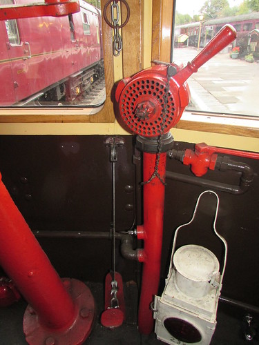
W233 Hawksworth Auto-trailer: Driver's Brake Application Valve (shown pinned 'out of use' in the 'released' position). Note the foot pedal to the left for the Gong.
Altogether, a most enjoyable (and not too strenuous) day.
Related posts on this website
Battlefield Line Steam Gala 2018 (Part 1).
The previous Steam Gala at the Battlefield Line had been in 2015 and my report on that event is here.
To see all my posts about the Battlefield Line, select Label 'Battlefield Line' or click here.
References
[ 1] ‘A Pictorial Record of Great Western Engines’ by J. H. Russell (Oxford Publishing Company Vol. 1 & 2 1975: reprinted as one volume 1978) SBN 0 86093 02 6.
[ 2] 'Brief History of Auto-trailers (BR) W233 and GWR No 169'(5542 Limited, second edition).
My photograph albums
Where necessary, clicking on an image above will display an 'uncropped' view or, alternately, pictures may be selected, viewed or downloaded, in various sizes, from the albums listed:-
5542 GWR Locomotive
W233 Auto-trailer
Battlefield Line Steam Gala 2018
Battlefield Line, 2017-2018
All my Battlefield Line albums
