skip to main |
skip to sidebar
A railway works largely on the principle of "See and be Seen". In the daytime, a driver can see where he is and observe the signals. People on or about the running lines, provided they keep a lookout, are aware of approaching trains and can ensure they are in a place of safety. But at night, it's not so simple. On roads, we're now accustomed to widespread artificial street lighting supplemented by powerful headlights on vehicles. On the early railways, this was not the case. Various schemes were tried out using a flaming fire brazier at the front of the train (to warn of the trains approach) or at the rear (to act as a warning to a following train).
The Tail Lamp
The red Tail Lamp established itself as the 'last line of defence' for a slow-moving or stopped train to warn a following train. Considerable effort was put into making these oil lamps reliable and visible. Although the actual flame used was small, when combined with glass 'bull-eye' or, more recently, cast glass 'Fresnel' lens, in good conditions these could be seen from a considerable distance. There's a little more in the post MIC - Lamps.
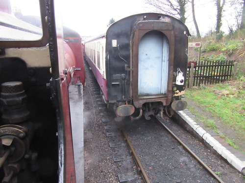 View of rear of passenger train on arrival at Shackerstone on the Battlefield Line, viewed from a second train waiting to leave. The oil tail lamp confirms that the train has arrived complete.
Traditional Railways in Britain
In general, railways in Britain are fenced so, in theory, members of the public are excluded and there is less need for a bright headlight to warn people of the approach of the train. Although locomotives typically carried white headcode lamps which could be set in different patterns, these were provided purely so that signalmen could confirm the type of train approaching both by day and at night.
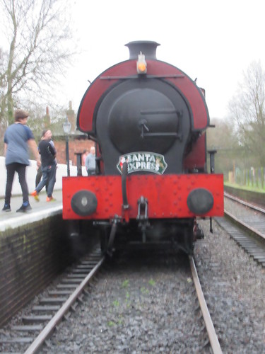
'Cumbria' (with headlamp lit) ready to return from Shenton. The single lamp near the chimney indicates an 'Ordinary Passenger Train'
At night, drivers faced blackness ahead, scanning the dark for the all-important signal indications. To preserve the driver's all-important 'night vision' there was little illumination on a steam locomotive footplate. It was normally restricted to a 'Gauge Lamp' which used rape seed oil (which is less flammable than paraffin) so that the fireman could confirm the boiler water level in the Gauge Glasses. Some locomotives were provided with a shield a shield between the firedoors and the driver's position to protect the driver from the glare when the firedoors were opened during firing. The driver had to orient himself by careful observation of his surroundings. Sound became important and drivers would know where they were from the sounds made by bridges, cuttings and other lineside features.
As railways developed, so did railway signalling to regulate the movement of trains. This evolution is briefly described here. Fixed signals were initially semaphore, as described in another signalling post here. At night, the indication was made visible by movement of the signal arm placing different coloured filters in front of the light from a small oil lamp, as described in the post Railway Signalling in Britain: Part 4 - Semaphore Signal Aspects by Night.
To enhance the visibility of signal indications further, methods of electrically illuminating signals were developed, resulting in Colour Light Signals where the semaphore arm (and moving parts) are eliminated and, by day and by night, the indication is given by various combinations of powerful coloured and white lights.
Modern Railways in Britain
Whilst less important routes in Britain still retain semaphore signalling, colour light signals are becoming universal. More recently, colour light signals using filamentary lamps are being replaced by multi-element Light Emitting Diode designs providing enhanced light outputs with greater efficiency. Most preserved railways (where speeds are generally moderate) continue to use mainly semaphore signals.
On the national railway network, oil tail lamps have been replaced by portable flashing battery-operated lamps using Light Emitting Diodes or, on multiple unit stock, built-in electric lights. With few signal boxes to observe the headcode of an approaching train, electric 'marker lights' are now provided at the front, together with one high-intensity white light to provide a warning to staff working on or about the line. This high-intensity light does give the driver some forward visibility at night but it mainly serves to improve the sighting of the various types of lineside reflective signs provided for the driver's guidance.
Railways overseas
Many overseas countries had unfenced railways, increasing the chances of members of the public being on the tracks at night so there was more need for bright headlights to act as a warning. I found a summary of the American experience in 'Presentation Magazine' at The History of the Railway Locomotive Headlamp.
Electrical Systems on Steam Locomotives
The use of electricity could increase the brightness of locomotive headlamps and offered more convenience over oil lamps which needed filling and trimming regularly. Some electric generators were introduced on steam locomotives in Britain but their use was far more widespread overseas, as described in the post Electrical Systems on Steam Locomotives.
[Reference to post 'Electrical Systems on Steam Locomotives' added: 14-Sep-2016]
Click on any picture or drawing below for a larger, uncropped view.
In the article Locomotive Regulators (part 1) I discussed early regulators for steam locomotives and the very common two-port slide valve designs.
Whatever the precise design, this steam valve, which allows the engine to move, is called the 'Regulator' or sometimes the 'Throttle'. It's a proportionate valve - the more the operating handle is moved, the more steam flows to the cylinders. The valve itself is usually mounted within the boiler, where the steam is generated, as part of the 'steam dome'. The steam dome is the highest part of the boiler to minimise the pick-up of droplets of water from the mass of water below. Alternately, the regulator valve could be situated in the smokebox - the Great Western developed a very successful smokebox regulator of the horizontal slide valve type.
Conventionally, the regulator is controlled by rotating the regulator rod passing through the boiler backhead so as to operate the regulator mechanism in the boiler. This rotation is achieved by pulling on what may be a fairly long handle attached to the end of the regulator rod on the footplate to give the driver sufficient leverage to be able to adjust the regulator valve against the pressure of steam inside the boiler. In the most common designs, the driver moves this handle in an arc. In 'Lion', for instance, it's fully closed with the handle at about 2 o'clock and fully open at about 10 o'clock. Different classes of engine have different detailed regulator design and sweep through different arcs. For instance, most Great Western Engines have a regulator handle which moves from 5 o'clock to 1 o'clock. I was surprised to discover that the regulator on the marvellous Great Eastern '1500' class moves from 4 o'clock to 8 o'clock ('underarm'). Left hand drive engines have mirror-image regulator arcs.
The steam pressure on the valves in the slide valve pattern helps to stop steam leaking past the valve but, as boiler pressures became higher and locomotives became more powerful, regulators could be quite hard to open or shut, sometimes needing the combined efforts of driver and fireman so some designs have two handles attached to one regulator rod - one, conventionally, pointing towards the driver's position, the second pointing to the fireman's side. The effort required, particularly to open a regulator onto 'Main Valve' (also called 'Second valve') can be quite demanding.
On smaller locomotives, a second regulator handle may be fitted because, during shunting, the driver may have a better view from the 'wrong' side of the cab and the second handle allows the driver better control of the movement. Some designs also provided a duplicate brake valve on the 'wrong' side. Where small shunting locomotives were used in private sidings, 'single manning' was often resorted to so the distinction between 'Driver' and 'Fireman' was lost.
Not all regulator handles would stay where they were put, but would tend to 'creep'. To counter this, enginemen might carry a wedge which could be placed between the regulator handle and the quadrant to prevent unwanted movement. In India, I found a chain used to prevent the regulator from creeping closed.
Many Overseas, L.N.E.R., S.R. and British Rail 'Standard' locomotives had 'pull-out' regulator handles moving fore-and-aft where the handle is pulled towards the driver to admit steam to the cylinders often, but not invariably, working a 'balanced' regulator. On Overseas locomotives with this feature, there is often a ratchet mechanism, released by a trigger handle, to prevent the regulator from 'creeping' from the set position, but I've not seen this feature on British-made engines used in Britain.
Plug and Butterfly designs (mentioned in part 1) were, as far as I know, only used in the early years of locomotive design so now we have just slide valve, balanced and multi-valve (as used, for instance, on LMS 'Pacifics') types to consider.
Vertical Dome-mounted Slide-valve regulators
The arrangement of this type of regulator was shown in part 1 of this post and the picture below shows a vertical slide valve regulator on the sectioned locomotive 'Pender' at the Museum of Science and Industry in Manchester (MOSI), where I was a Volunteer for many years (resulting in a number of posts about MOSI here).

There are also a couple of pictures in the post The Best Laid Schemes ... which describes the failure of a regulator linkage.
Horizontal Dome-mounted Slide-valve regulators
As boilers became larger, vertical dome-mounted regulator valves could be hard to fit within the loading gauge. At the L.M.S. Stanier, with his Swindon background, originally adopted the Great Western approach of a slide-valve regulator mounted in the smokebox but, with the introduction of his 4-6-0s, he produced a dome-mounted horizontal slide valve regulator which most enginemen liked.
In the diagram below, 14 is the port face forming the start of the main stam pipe which has with three ports, covered by the main valve 8 when the regulator is shut. The main valve 8 is provided with two narrow openings 6 and 7 which are normally open to steam and two main ports 11a and 12a each divided into three which are closed to steam until the main valve 8 is displaced from the closed position. The pilot valve 5, when closed, obstructs the narrow openings 6 and 7 in the main valve but does not impede steam through main ports 11a and 12a. To open the regulator, the regulator rod is rotated, pivoting the actuating rod 3 which moves the actuating rod 4, forcing the pilot valve to move, successively opening narrow openings 6 and 7 so that steam flows from the dome to the main steam pipe. The actuating slot in the top of the main valve is wide, so that the actuating rod 4 does not start to move the main valve until pilot ports 6 and 7 are fully open, then main ports 11a and 12a allowing increased steam flow.

Balanced 'Double-beat' regulators
To reduce the effort required by the driver in making adjustments to the regulator, the balanced, or 'double-beat' regulator was introduced. An early form was produced by Ramsbottom. Later, Lockyer patented a version used by the North Eastern Railway. In the form used by Gresley,the balanced regulator allows steam on both sides of a lifting bobbin-shaped valve so reducing effort required to adjust the valve. The horizontal regulator rod (pushing from the right of the diagram below) operates the bell crank so as to lift the valve from its seating, allowing steam to flow from the dome to the main steam pipe.

'Flying Scotsman' has this type of valve. My post 'Flying Scotsman' has a contemporary drawing here. If you select one of the the larger sizes of the drawing, you can see how the balanced regulator is fitted into the boiler. The LNER (always masters of self-publicity) described the regulator as giving 'finger tip control'. Whenever I've driven 'Flying Scotsman', I've found the regulator provides nothing that could be remotely described as giving 'finger tip control'. There's a brief description of my early meetings with the locomotive here. The only 'A4' Pacific I've driven ('Sir Nigel Gresley), whilst otherwise a superb machine, was just as bad as far as ease-of-operation of the regulator goes.
Multiple Valve regulators
As far as I know, these were only used on large, superheated locomotives. A number of satisfactory designs of superheater were developed but The Superheater Company Limited achieved widespread success, marketing products under its 'MeLeSco' trade mark worldwide. It also developed a multiple valve regulator, which I think was used by the L.M.S. and L.N.E.R. and achieved worldwide sales well in excess of 40,000 units! The design (shown in the diagram below) is based on a modified superheater header casting where the forward part of the casting is divided into three transverse chambers, one above the other. The top chamber is connected to the superheated steam output from the superheater. The middle chamber connects to the main steam pipes, delivering superheated steam to the cylinder steam chest. The bottom chamber is a balancing chamber. A series of fairly small valves control the passage of steam from the top to middle chamber. These valves are progressively opened and closed by cams on a rotating camshaft operated by the regulator handle. Initial movement of the regulator handle first opens a pilot valve which admits steam to the balancing chamber so that further movement of the regulator requires little effort to open, in turn, each of the main valves.

I drove Princess Margaret Rose on one of her visits to Tyseley years ago but don't recall how I liked the regulator action using a multiple valve regulator - my impression was of a magnificent (and big) engine.
A Regulator Gallery
I like the Great Western regulators which I've experienced on a number of classes. The regulator on 5080 'Defiant' really was 'finger-tip' - I'm sad that she's now on static display at Buckinghamshire Railway Centre.

Standard Great Western regulator handle on 2-8-0 '3803'. Note the round counterweight.
Stanier regulator handle on 2-8-0 '8624'. Note the sprung stop bearing on the quadrant, preventing 'creep'.
In 1992, I had an opportunity to drive a Class 'WP' on the main line in India. There's a brief description of this trip buried in the post here.
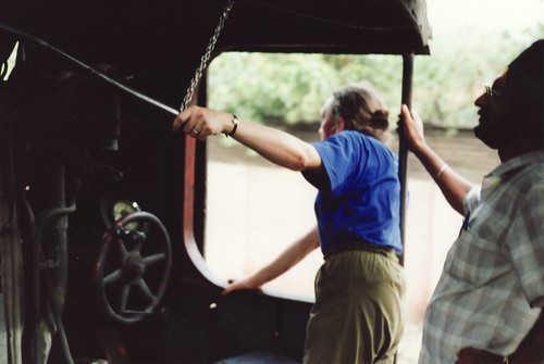
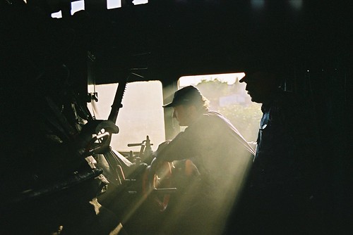
Class 'WP' in India: I'm holding the regulator handle through force of habit - at this point, we've attached a chain from the roof to the handle to prevent the regulator from closing itself.
The only American-built class I've driven is an 'S160' (with a ratcheted regulator handle) at Peak Rail. On tugging open the regulator, there was a distinct delay, followed by a 'clang' from the dome (which, at the time, I commented "sounded like a dustbin lid being rattled"), then steam flowed.
 The spartan lines of an 'S160' (Photo: lner.info)
In 2003, I was fortunate in driving three different locomotive classes at Wolsztyn in Poland. There's a post called, simply, Poland with a link to pictures.
 Pm36-2 'Piekna Helena' en route to Lesno (the 'arty' shot). The regulator arc is from about 1 o'clock to 11 o'clock.
In 2005, I had the opportunity to drive three Russian-designed classes in Ukraine - the first of a series of posts is at Ukraine 2005 with links to pictures.
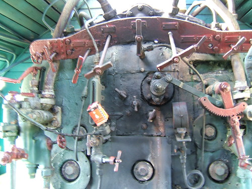
Russian-designed Su 251-86 in Ukraine showing boiler backhead with short regulator handle (with ratchet) rotating the regulator rod via a link.


