On Saturday 12th August 2017, I was back at the Battlefield Line, this time on 'Cumbria' which had recently had a washout and repairs to the fireman's side injector.
There was no footplate experience course booked so it was a leisurely start for me signing on at 08:30, although Adrian L. (who was acting as fireman in the morning) had arrived a couple of hours earlier to get the engine lit-up. In addition to the normal service of five return trips between Shackerstone and Shenton, in the evening there was a 'Fish and Chip Special' which I'd also agreed to 'cover'.
I 'oiled round' and examined 'Cumbria' and we were 'off shed' in plenty of time to attach to our 4-coach train waiting in platform 2 at Shackerstone. After the first two round trips to Shenton, Adrian was replaced as fireman by Steve A. But Adrian had not finished - on the contrary, donning his 'catering' hat, he and Gina spent the afternoon sorting out supplies for the evening 'Fish and Chip Special' whist Steve and I completed the normal 'diagram' with another three journeys to Shenton and back.
Arriving back at Shackerstone after our fifth trip, we were routed into platform 1 where the main station facilities (tea room, museum and toilets) are located. I deliberated 'stopped short', leaving room at the north end of the platform for our train to be 're-inforced' with an additional coach for the fully-booked evening special. Steve uncoupled 'Cumbria' and we went to the north end sidings to 'coal-up'. The bucket loading shovel (driven by Adrian wearing another 'hat') soon topped-up our bunker. We then shunted south through platform 2 to replenish the saddle tank from the water crane at the at the south end of platform 2. In defiance of normal conventions, turning the wheel which controls the water valve clockwise opens the valve, rather than closing it. Many years ago, as a reminder, somebody wrote on the wheel in white paint 'Open' and 'Closed' with arrows but this is now faded. If I'm on the wheel, I always have to do a 'double-take' when I hear the cry "That'll do" from my mate on top of the tank to avoid both of us getting a soaking.
Water Crane at Shackerstone. The wheel which controls the water valve is on the right.
Coaled and watered, we coupled onto the south end of the four coaches we'd left in platform 1 and I was able to watch the shunting being performed. The maroon-painted coach to be added to our train was behind the self-powered Tamping Machine in siding 2 at the north end so Adrian (now with driver's 'hat') 'fired-up' the tamper and moved into platform 2, pulling the extra coach. The Class 04 diesel shunter moved onto the north end of our train and attached the nearest coach (a 'Mark 1' in Western Region 'chocolate and cream' livery), first drawing it back to the north end, then propelling it onto the maroon-coach behind the tamper in platform 2. The '04' then pulled both coaches back to the north end, before finally propelling them towards the coaches waiting in platform 1.
Adrian leaning out from the '04', checking for handsignals from the shunter, as he propels two coaches onto the three already in platform 1.
British passenger coaches built after the 1948 Nationalisation of railways were fitted with 'Buckeye' couplings, retaining a conventional drawhook which is used to attach the locomotive using a screw coupling (only one British steam class was originally fitted with 'Buckeye' couplings - Gresley's 'A4'). On coaches, the 'Buckeye' is hinged and has to be lifted to the horizontal position to allow coupling to a similarly-fitted vehicle. The substantial hook has a hinging 'knuckle'. To couple, two vehicles are brought together with one of the knuckles in the 'open' position and the adjustable buffers set to the 'Short' position.
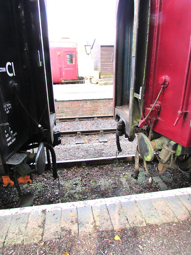
BR Coaches being shunted together. Buffers in 'Short' position for use with Buckeye coupling. Note 'saddle' stowed on bracket adjacent to buffer.
As the two couplings contact, the open knuckle is forced closed and a mechanical latch drops, locking the knuckle closed. In addition to the shunter confirming visually that 'the pin' has dropped, a 'pull test' is conducted where the locomotive tries to separate the vehicles. Unfortunately, to connect the brake hoses and, when required, the steam heating hoses, the shunter still has to clamber underneath the vehicles. The electrical jumpers to allow the guard to control the carriage lighting also require connection.
To uncouple, pulling a chain on either coupling unlatches that knuckle, allowing the vehicles to be drawn apart. The shunter controls the coupling and uncoupling by hand signals given to the driver of the locomotive performing the shunt from a position alongside the vehicles.
It was a warm summer evening and, by this time, a good-natured crowd of expectant diners had assembled on the platform, waiting to be seated on the train. Steve and I readied 'Cumbria' for a leisurely trip down the line.
'Cumbria' ready to depart with the evening train.
A little late, we received the 'Right Away' from the Guard, collected the Single Line Staff from the Signalman at Shackerstone and trundled down the line. We were not expecting to stop at Market Bosworth but, as we approached the platform, one of our Volunteers was on the platform so we decided to make a stop. He didn't board the train, but had apparently ordered a portion of fish and chips which was safely delivered to him, after which the Guard gave the 'Tip' and we set off again.
I'd been told to stop on Shenton Bank, just before our last station, where there are views across the Leicestershire countryside on both sides of the train. It was a perfect summer evening as the sun sank lower in the sky and the engine simmered quietly whilst our diners enjoyed their food. I felt much happier than the picture below perhaps suggests.
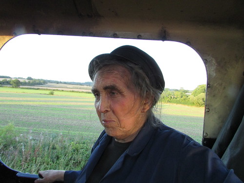
Battlefield Line Fish and Chip Evening Special: We paused on Shenton Bank with views across the Leicestershire countryside.
Food had also been ordered for the loco crew, so Steve 'dropped down' and walked back to collect our fish and chips which we enjoyed whilst waiting. After about fifteen minutes, the Guard gave us the 'Right Away' and we continued to Shenton station. There was then a bout of activity as we uncoupled, ran round and coupled onto the train for the journey back to Shackerstone. Many of our passengers were on the platform, enjoying the warm evening and taking numerous photographs. Once everyone was back on board, we set off on a fairly gentle trip back to Shackerstone.
We arrived back in platform 1, stopping so that all the passenger coaches were in the platform. With 'five on' that meant that the rear of the train didn't leave sufficient clearance for us to use the ground frame giving access to the loco shed. So we ran round, attached to our train and, with the Guard giving hand signals from the north end, propelled the train northwards a short distance to give sufficient room for us to get 'onto shed'. By this time, it was fairly dark. It only remained to put the locomotive in the shed and carry out the normal disposal routine after what had been a very enjoyable day.
Related posts on this website
To see all my posts about the Battlefield Line, select Label 'Battlefield Line' or click here.
My photograph albums
Where necessary, clicking on an image above will display an 'uncropped' view or, alternately, pictures from may be selected, viewed or downloaded, in various sizes, from the albums listed:-
Battlefield Line Fish and Chip Evening Special.
'Cumbria'.
All my Battlefield Line albums.
Saturday, 26 August 2017
The Role of the Shunter (2)
The Mutual Improvement Classes of the old steam railways still continue for today's preservation volunteers. This is one of a series of posts based on notes of talks given by Jan or with technical content which may be of use to today's volunteers. To find them all, select label 'MIC' or click here. There is also a list of these posts (not always up-to-date) here.
There is an earlier post which introduces the role of the shunter here and the comments on safety in that post equally apply here. The introductory post discussed simpler coupling systems widely used on standard-gauge freight rolling stock. This part discusses couplings used on passenger rolling stock.
Screw Couplings
Whilst the 'loose coupling' provided by three-link couplings was acceptable on freight trains, passenger vehicles needed to be more tightly coupled to give a reasonable level of comfort. For many years, passenger coaches in Britain used 'screw-couplings'.
Vehicle with Screw Coupling hanging: End view (from a Railtrack document).
Vehicle with Screw Coupling stowed on hook: Side view (from a Railtrack document).
Once the coupling is on the drawhook of the adjacent vehicle, it is tightened up by rotating a threaded screw which has one end with a left-hand thread, the other end with a right-hand thread, using a built-in tommy bar incorporating a counterweight. This draws the two D-links together tightening the coupling so that, on straight track, the buffers will be equally compressed but, on curves, the buffers on the inside of the curve will be further compressed and the buffers on the outside of the curve will slacken slightly. At all times, the buffers should remain under some compression, so that the train cannot bang in and out. The comfort of the passengers depends upon the screw adjustment being correctly carried out. The complete process of coupling vehicles is outlined in the article On the Footplate (Part 2).
The picture below shows restored L.M.S. coach 7828 attached to 'Austerity' Tank 'Lord Phil' at Peak Rail.
Restored coach 7828 at Rowsley: View showing coach drawhook, with unused coach 'D' link hanging down. The rest of the stowed coach screw coupling is obscured by the steam heating hose. The coach has been attached to 'Austerity' Tank 'Lord Phil' using the locomotive coupling.
Although screw couplings were effective, the results of accidents, particularly at higher speeds, showed the limitations of screw couplings. Part of the train could twist or even break free, increasing the chance of serious injuries.
Automatic Couplings
In other countries, various forms of 'Automatic' coupling had been developed to provide extra strength and simplify the business of coupling and uncoupling vehicles. In America, Eli Janney patented his design in 1873 and, in 1893, legislation made this the standard coupling in America. In 1915, John Willison of Derby patented his own automatic coupling which, with modifications, was adopted in 1935 by the Soviet Union as their standard coupler.
Ukraine Steam: Locomotive Em 735-72 at speed in the rain, showing Russian pattern autocoupler between tender & coach.
A variation of the Janney coupling with side release called the 'Buckeye' was adopted by the L.N.E.R. and the Southern in the 1930s, retaining side buffers. Since not all vehicles were fitted with 'Buckeye' couplings (and only one class of British steam locomotives was fitted - Gresley's 'A4'), the 'Buckeye' fitted to coaches was a 'drophead' pattern where the automatic coupler head could be lowered to reveal a conventional drawhook for use with a screw coupling. After the 1948 Nationalisation of British railways, a range of standard passenger coaches were built, similarly fitted with a conventional drawhook, 'drophead' 'Buckeye' coupler and adjustable side buffers (each with two positions - 'long' for use with a conventional screw coupling and 'short' when using the 'Buckeye').
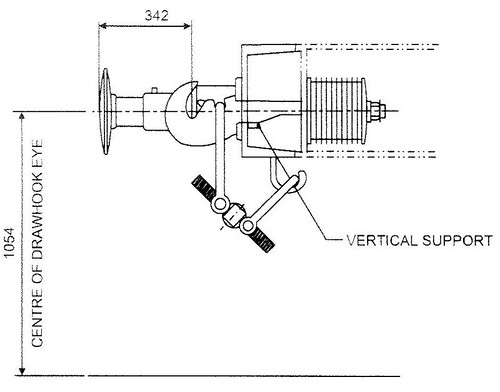
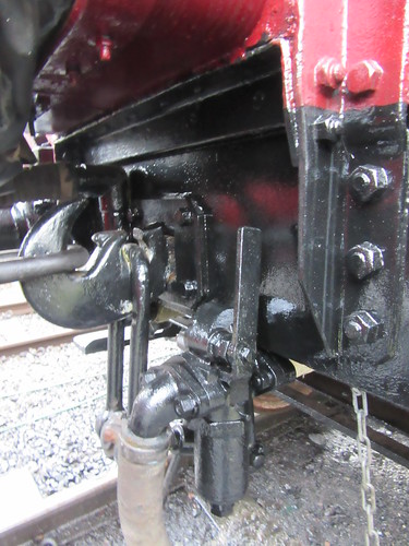
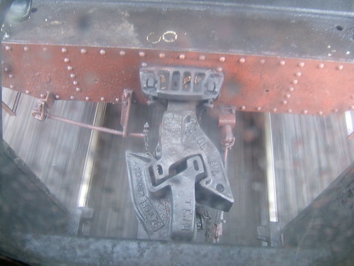
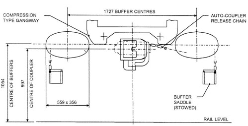
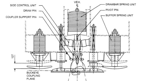
Buckeye Coupling as fitted to B.R. Mk 1 and Mk 2 gangwayed vehicles: End view (from a Railtrack document).
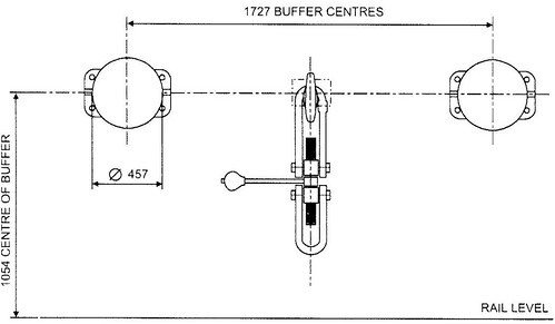
Buckeye Coupling as fitted to B.R. Mk 1 and Mk 2 gangwayed vehicles: Top view (from a Railtrack document).
Buckeye Coupling as fitted to B.R. Mk 1 and Mk 2 gangwayed vehicles: Side view (from a Railtrack document).
The 'Buckeye' has a substantial hinging 'knuckle'. To couple, two vehicles are brought together with one of the knuckles in the 'open' position and the adjustable buffers set to the 'Short' position, as shown in the picture below.
BR Coaches being shunted together. Buffers in 'Short' position for use with Buckeye coupling. Unused 'saddles' are stowed on a bracket adjacent to each buffer.
As the two couplings contact, the open knuckle is forced closed and a mechanical latch drops, locking the knuckle closed. In addition to the shunter confirming visually that the 'pin' has dropped, a 'pull test' is conducted where the locomotive tries to separate the vehicles.
To uncouple, pulling a chain on either coupling head unlatches that knuckle, allowing the knuckle to swing open and the vehicles to be drawn apart.
When coupling or uncoupling the shunter stands alongside the vehicles and controls the movement by hand signals given to the driver of the locomotive performing the shunt. Unfortunately, to connect or disconnect the brake hoses and, when required, the steam heating hoses, the shunter still has to clamber underneath the vehicles, after coming to a clear understanding with the driver that it is safe to do so. The electrical jumpers between vehicles which allow the guard to control the carriage lighting also require connection/disdconnection.
Related posts on this website
The Role of the Shunter (Part 1).
On the Footplate (Part 2).
MIC - Brakes.
Mutual Improvement Classes (2) (List of MIC posts).
My photograph albums
Where necessary, clicking on an image above will display an 'uncropped' view or, alternately, pictures from may be selected, viewed or downloaded, in various sizes, from the albums listed:-
Passenger Rolling Stock.
['Related posts' amended 13-Apr-2020]
Subscribe to:
Posts (Atom)