I'm afraid this report, covering the end of 2014 and 2015 is delayed (my fault), but in the interests of completeness, it's finally being issued. This report is based on information provided by Dr. Hla Tun, who also supplied the photographs.Shwe Sin Minn
In October 2014, Dr. Hla Tun arranged for one of the guides working on the 'Road to Mandalay' ship to make a donation towards teachers' salaries at the Shwe Sin Minn Nunnery, Orphanage for Girls and Monastic Secondary School. Guests from the ship also donated rice, peanut oil, garlic and onions. Shwe Sin Minn is situated in Maymyo, up in the hills, around two hours driving from Mandalay. Maymyo was very popular with the British in summer, because of its cooler location.
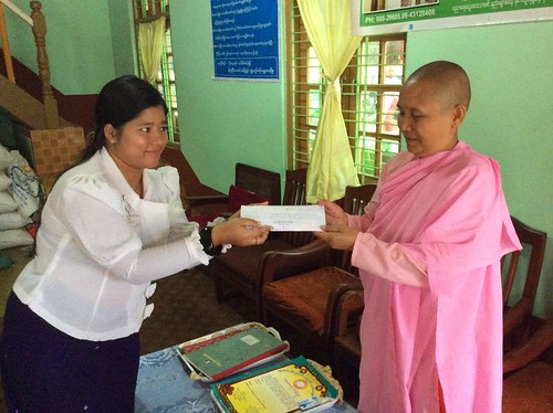 Teachers' salaries being donated to one of founders of Shwe Sin Minn.
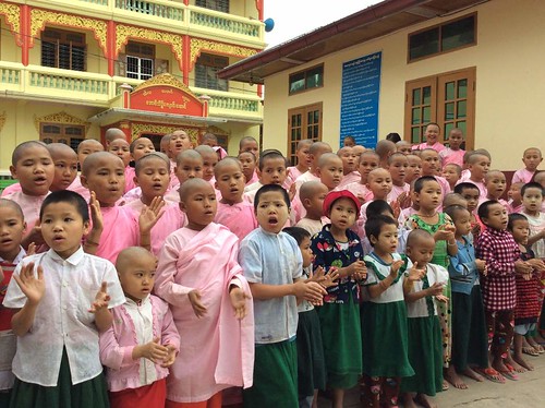 Girls at Shwe Sin Minn reciting a poem for their visitors.
A report on my first visit to Shwe Sin Minn in 2011 is here My pictures of this visit and a later visit in 2013 are here.Traditional Ceremonies
The following pictures show a procession in connection with traditional ceremonies. These are arranged in connection with Noviciation for boys and Ear Piercing for girls and feature decorated, gold-painted oxcarts.
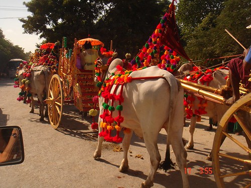 A procession of decorated oxcarts.
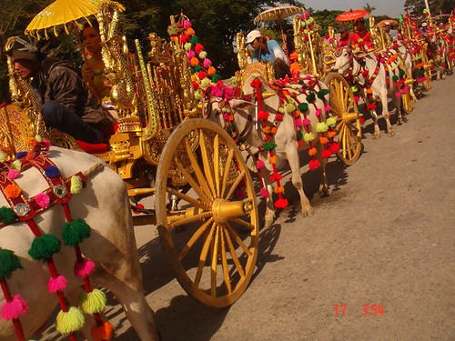 Another view of the procession.
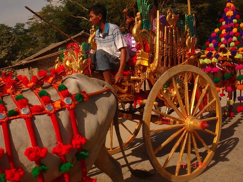 Close-up of one of the gold-painted oxcarts.
I'd been lucky enough the see this ceremony in 2012 at Moe Dar (report here), in 2013 at Bagan (briefly mentioned here) and in 2013 at Mandalay (briefly mentioned here).Taung Be School Stationery Distribution and Concert
Taung Be school is only a few minutes walk from the Bagan Medical Clinic and the 'Road to Mandalay' landing stage in Bagan. On 25th October 2014 Dr. Hla Hun, accompanied by Guests from the ship, visited to distribute stationery to about 371 students. The picture below shows Grade 5 students from the school, dressed in traditional Shan Costume, performing a traditional dance from Inle Lake.
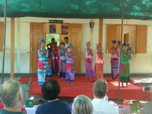 Taung Be Concert
There's an earlier report on stationery distribution at Taung Be during 2013 here.Aung Myae Oo Monastic High School
On 16th December 2014, Dr. Hla Tun visited this school in Sagaing which has 2,092 students from Grade 1 to Grade 11 of whom 691 are boys and novices and 1,401 are girls and nuns. There are 43 teachers on the staff.
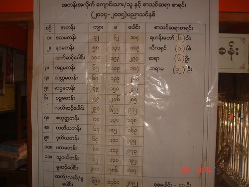 List of students.
On that date, students from Grades 5 and 9, most of whom were nuns, were sitting their State Examinations.
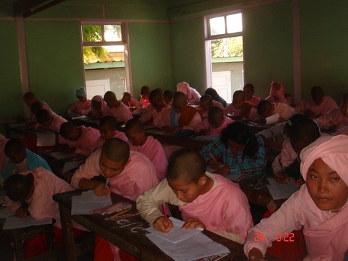 The State Examinations in progress.
The Doctor made a donation to one of teachers, watched by small children (who were on holiday because of the State Examinations) and the Monk.
 Dr. Hla Tun making the donation.
Christmas Eve, 2014
On Christmas Eve, 15 orphans from Nar Ga and Tribal Orphanage, Mandalay, came on board the 'Road to Mandalay' to perform Christmas carols for the guests. The performers ranged from a 7 year attending Grade 3 to a 16 year in Grade 11. Among them, there are 6 orphans from the Nar Ga Tribe/Ethnic and 9 from the Chin Tribe/Ethnic. The group was led by a teacher, Ms. Ann Ja Taung who is also Chin Tribe/Ethnic.
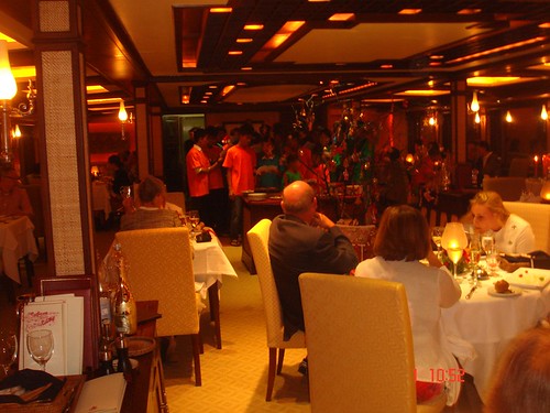 Singing carols to the Guests in the restaurant of the 'Road to Mandalay'.
After the performance, Dr. Hla Tun made a donation to the Orphanage.
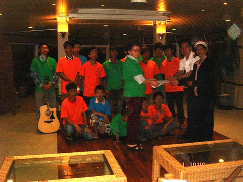 Dr. Hla Tun making a donation to the Orphanage.
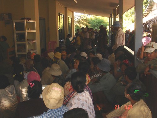
Ko Dut Drop In Centre
Donations have allowed improvements at this Drop In Centre in Mon State. The planned first floor has been brought into use by constructing a new floor and access stairs. The exterior has also been painted. These pictures, taken in February 2015, show the work in progress.
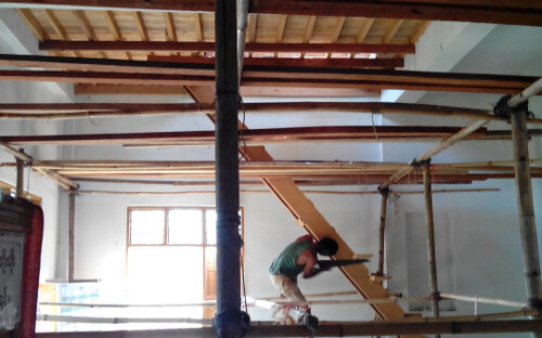 Ko Dut Drop In Centre: Improvements funded by donations - upper floor with access stairs being added.
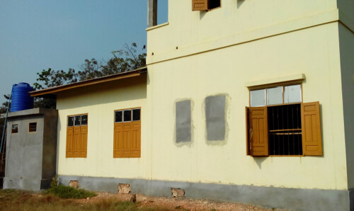 Ko Dut Drop In Centre: Improvements funded by donations.
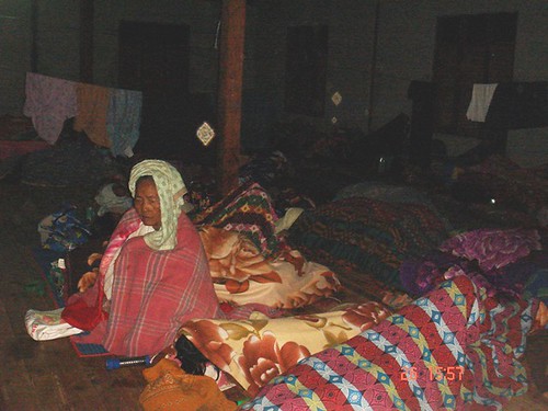
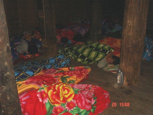
I first visited Ko Dut in 2014 and there is a report here. I returned in 2015 (and inaugurated the new upper floor by the simple process of sleeping on it) as described here.All my posts on Educational Support in Burma can be found here.


