The 'T9' were nicknamed "Greyhounds" for their speed and free running. They had a long life, albeit with various modifications and, when the last of the class was withdrawn in 1963, it became part of the National Collection managed by National Railway Museum.
I'd always admired the class and when I had an invitation, around 1990, to visit Swanage to drive the preserved locomotive (then in LSWR livery and carrying the original number 120), I leapt at the chance. Sadly, when I arrived at Swanage I found out the engine had been 'stopped' for a hot axlebox on the 8-wheel tender. I still got my couple of days driving there but on the Johnson 'Half-Cab' 0-6-0 side tank, which I found a charming locomotive and surprisingly powerful.
Many years later, in 2013, the 'T9' visited the Battlefield Line. This time, it was British Railways lined black 'mixed traffic' livery and sporting the number 30120 which corresponded better with its modified appearance with extended smokebox and stovepipe chimney. Sadly, I wasn't rostered on the 'T9' during its visit but working on the diminuitive Beattie Well Tank alternating departures with the 'T9' was a special experience (described in the post here).
The 'T9' returned to Shackerstone for the 2015 'Santa' trains, alternating departures with 'Austerity' tank 'Cumbria'. Although I was originally rostered on the 'T9' on two of the 'Santa' days, they both were swopped to the 'Austerity' as described here. The 'T9' remained at the Battlefield Line for the start of the 2017 season but when my booked turn on the 'T9' in March was cancelled, I began to think that I was fated never to team-up with Drummond's classic.
However, on Saturday 8th April 2017, I finally got to drive 30120 at the Battlefield Line with Adrian L. acting as fireman and Graham L. cleaner.

Drummond 'T9': 30120 during preparation on 8th April 2017.
I had a second turn on Easter Sunday, 16th April 2017, this time with Jamie W. as fireman. My brief assessment of the locomotive? "Proper Job".

Drummond 'T9': 30120 during preparation on 16th April 2017.
Preparing the 'T9'
When the modernisation of British Railways in the 1950s introduced more complex diesel and electric traction, specific training of drivers and (where provided) secondmen for the different classes of motive power was regarded as essential. But earlier, in the steam era, once footplatemen were 'passed out', they were normally expected to sort out for themselves how to prepare, fire and drive whatever class of engine came along. Originally, I thought this must have been a daunting task but, over the years, I've learned to appreciate the challenge. Despite the variety of designs, the basic principles of steam locomotives have remained remarkably unchanged since the early days and intelligent observation, sometimes coupled with tips from other crews, can solve most queries. So, I enjoyed clambering over the 'T9' and finding out how Drummond had produced his 'masterpiece'.
During his time on Scottish railways, Drummond had learnt the value of rugged, reliable construction and the 'T9' fully embodied these principles. I was impressed by the 1-inch thick steel frames, the robust castings and forgings, the generous bearing areas and the overall simplicity of construction.
The Motion Plate supports the rear of the slide bars and must provide a rigid anchorage, as shown in the picture below. Stephenson Link motion was employed (the increasing popularity of Walschaert's motion in England came rather later). However, well-designed Link motion serves most needs and Drummond's arrangement was considered very successful. The picture below also shows the curved Expansion links which allow alteration of cut-off and direction of travel, in the case of the 'T9' under the control of steam reversing gear.
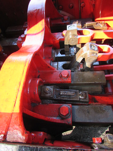
Drummond 'T9': View between frames from left side, showing rear of Motion Plate and Expansion Links.

Drummond 'T9': View between the frames, looking rearwards. L-R: Hornguide for right driving wheel, Right crank (on back dead centre), Four eccentric rods and eccentric sheaves, Left crank (on bottom quarter), Hornguide for left driving wheel.
I was impressed by the compact design of the two-cylinder steam reversing gear, with the cylinders mounted vertically in-line inside the left main frame, just ahead of the left driving axlebox.
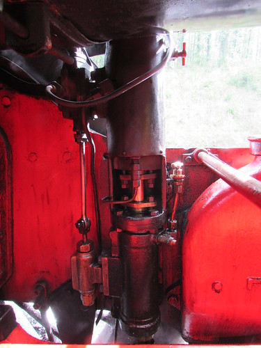
Drummond 'T9': Steam Reverser, mounted inside left main frame.
30120 has the earlier-pattern 'narrow' cab which could be described as 'cosy'. The splashers of the trailing coupled wheels protrude into the cab on both sides and these are extended rearwards to form small toolboxes with a wooden seat on top.

Drummond 'T9': 30120 has the earlier-pattern 'narrow' cab.
The Driver's duties
On most early steam locomotives, the driver's position was on the right of the footplate. Industrial locomotives were usually (but not invariably) right-hand drive. The Great Western Railway stayed with right-hand drive to the end (and beyond - prior to Nationalisation in 1948, the Great Western Railway placed an order with private contractors for 200 of the '94XX' class 'Pannier' tank, leaving British Railways to pick up the bill, as I mention in the article here).
But, on double-track railways in Britain, we drive 'on the left' and, as a consequence, the most convenient position for signals is further to the left. Generally, the driver will have a better view of signals on the left of the track if he is on the left of the footplate. Over time, modern locomotives in Britain became left-hand drive. Some had originally been right-hand drive and were rebuilt as left-hand drive. The iconic 'Flying Scotsman', proudly exhibited at the British Empire Exhibition in 1924, was built as right hand drive, as you can see from the drawing in the article 'Flying Scotsman'. 'Flying Scotsman' had been rebuilt with left-hand drive many years before I first got my hands on her at Birmingham Railway Museum in 1992 (described here).
The 'T9' is left-hand drive so the main driving controls are on the left of the cab - Reverser, Regulator and Vacuum Brake.
Reverser
Steam-operated power reversing gear is fitted, controlled by a short lever painted red which stands vertical except when changes to setting are required.
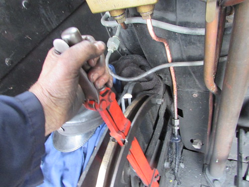
Cab Reversing Lever being placed in 'neutral', having just 'Linked-Up' the gear in 'Forward' to the position indicated by the white-painted pointer which moves over the engraved, brass cut-off indicator scale.
I'm afraid I found a tendency for the gear to 'creep' towards full gear when travelling forwards but reverse gear was better-behaved.
Regulator
The regulator is closed in the 'seven o'clock' position. It is progressively opened 'underarm' as the lever is pushed towards 'four o'clock' (the only other engine I can remember driving with an 'underarm' regulator was the 'B12', which was right hand drive - this is mentioned in the post Locomotive Regulators (part 2)).
Vacuum Brake
A combined fitting provides small ejector, large ejector, driver's brake application valve, vacuum relief valve and release valve together with a horizontally mounted handwheel on the shut-off cock. Vacuum brake cylinders are provided on both locomotive and tender. The tender brakes can also be applied from a handwheel.
Blower Valve
The Blower Valve Handwheel is tucked in the front left corner of the cab, only accessible to the driver. More modern practice favours a position accessible to both driver and fireman. The actual blower valve is located adjacent to the smokebox, operated by a rod passing through the left handrail.
The Fireman's duties
As commented above, early steam locomotives tended to be right-hand drive, meaning the fireman normally worked from the left side of the footplate, favouring right-handed firing. But on the 'T9' and many other designs (later LMS, LNER, SR and BR locomotives) the fireman is on the right, favouring left handed firing. Some fireman were happy either way round, others permanently grumbled if forced to fire the 'wrong' way. Drivers could get bad-tempered if they felt that their fireman was 'invading their space' and there are many tales of drivers drawing a chalk line down the middle of the footplate - I recount one of these in the post A Day on the Footplate (2).
There's a (still incomplete) introduction to firing steam locomotives at MIC - Firing Steam Locomotives (1).
The position of the coal supply in the bunker or tender also varies between designs, sometimes being delivered at footplate level, requiring the fireman to bend, sometimes appearing at a raised shovelling plate (often called the "married men's tender").

Drummond 'T9': Watercart tender, showing raised shovelling plate, tender handbrake and large toolbox.
The coal then has to be fed through the firehole which, according to locomotive class, varies in shape, size and height above the footplate and can be equipped with different patterns of firedoor requiring some adaptability on the part of the fireman. The 'T9'has a top-hung, inward-hinging cast firedoor which can be held open at various angles by the use of a ratchet, controlling the amount of 'secondary' or 'top' air admitted to the firebox. The top-hinging means that a separate Baffle Plate is not required - when open, the door acts its own baffle. This design was quite widely used in this country (certainly by the L.N.W.R and Lancashire and Yorkshire Railway) and also overseas. The cast door can be a little heavy to work frequently but a hinging half-flap is provided which, when raised, may allow the firedoor to remain open.
Great Western firemen became adept at winding the chain from a similar flap-plate around the operating handle of the main, sliding firedoors. A 'pull' on the chain would then 'flip' the flap-plate open or shut with very little effort, leaving the main firedoors open. If the steaming rate demanded was not too high, they would leave the flap-plate shut and fire 'over the top', which required accurate shovel-work.
Stanier engines for the L.M.S. had a similar flap-plate, allowing a similar technique to be adopted.
The Great Northern Railway (later the L.N.E.R.) used a 'Trap-Door' design of firedoor, very convenient in use, once the technique was mastered. There's an introduction to this firedoor in the article Firing a 'B1'.
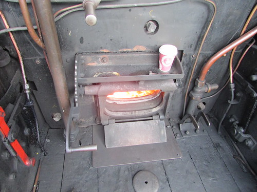
Drummond 'T9': Firehole with top-hung, inward-hinging firedoor. Note Flap Plate.
Different designs of firebox then require different firing techniques to produce steam economically. The 'T9' has a reasonably long 'box', almost 7 feet long front to back inside (nowhere near the length of, say, a Great Western 'King') with a sloping grate. If the fireman is lucky, when 'on the road', he can feed coal to the back the firebox (nearest the footplate) and the motion of the engine will trickle it forward to the front.
The 'T9' Tender
The preserved 'T9' has the distinctive 8-wheel 'Watercart' tender, giving a coal capacity of 5 tons and a water capacity of 4,000 gallons. Unusually, the two 4-wheel bogies are provided with inside axleboxes. Although tenders carried on eight wheels are very common overseas, I can only recall designs with outside axleboxes. A locomotive depends upon its supply of water as discussed in the post Water, water, everywhere. This was particularly important for the L.S.W.R. (later Southern) lines as they stretched far west into the territory of the Great Western Railway but, alone amongst major British railways, no water troughs were ever installed. On the West of England services, changing engines was frequently undertaken at Salisbury and, of course, water was available at major stations and yards.

Drummond 'T9': The 8-wheel 'Watercart' tender is provided with inside axleboxes.
Passage of Water from Tender to Boiler
Water from the tender is fed by gravity via two water cocks set in the wooden floor of the cab to two live steam injectors, one on either side of the firebox.
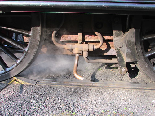
Drummond 'T9': Driver's side Live Steam Injector, suspended on a simple bracket alongside the firebox. The connections are (L-R): Delivery to boiler, Overflow, Cold water, Steam.
The injector uses steam from the boiler to pressurise the water to greater than boiler pressure (a feat of apparent magic possible due to the work of mathematician Bernoulli and engineer Henri de Giffard), allowing the water to feed the boiler through a one-way valve called a Clack Valve (there's a little more about the Clack Valve in a post here). In this way, water boiled into steam and converted into motion in the cylinders could be replenished. The steam for the injectors is taken from the top of the firebox and controlled from the cab by the Injector Steam Valves.
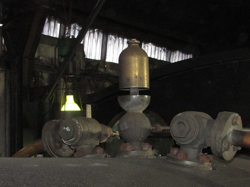
Drummond 'T9': View showing top of firebox with whistle and, left and right, Injector Steam Valves controlled by long rods extending to handwheels in the cab.
The pressurised water from the injectors is fed into the boiler via clack valves on the horizontal centre line of the front ring of the boiler shell on both sides. This was the 'classic' position for introducing feed water into locomotive boilers until the advantages of 'top feed' were understood in the 20th century.
 Drummond 'T9': 30120 being prepared at Shackerstone, showing the position of the Driver's Side Clack on the 'front ring' of the boiler shell.
Related posts on other sites
Brief data on 30120 and 'T9' (Rail UK Site).
Related posts on this site
Dugald Drummond and the 'T9' - Historical Background.
My Pictures
Where necessary, clicking on an image above will display an 'uncropped' view or, alternately, pictures may be selected, viewed or downloaded, in various sizes, from the album listed:-
Drummond 'T9'.
