In the development of the locomotive engine the initial challenge was to make the machine go. Stopping was less of a priority and early braking systems were rudimentary (or absent). But as designs improved and the weight and speed of trains increased, the need for effective brakes became a priority. The common arrangement was a shaped brake block which could be clamped against a wheel tread, dissipating the energy of motion as heat. Although wooden brake blocks were originally common, their tendency to burst into flame encouraged the use of cast iron which wears away with the friction, neccessitating periodic replacement. To provide more retardation, brake blocks on a number of wheels could be coupled together by a mechanical linkage and operated from a manual handle, often via a screw arrangement. To provide still more brake force, steam-operated brakes were introduced. In the early years, the driver could only operate brakes on the locomotive. The train was braked by the Guard applying a hand-operated brake in the Guard's vehicle at the rear of the train and, in some cases, by assistant Guards applying hand-operated brakes on intermediate vehicles. The shortcomings of this arrangement gave rise to pressure to introduce better braking systems operating on the whole length of the train. Systems using cable (such as the Heberlein cable brake in Germany, described in a Wikipedia article here) and the Clark and Webb chain brake use by the London and North Western Railway in the U.K. for a time were tried but eventually two approaches triumphed, using either air or vacuum.
Braking on the Great Western Railway
Great Western engines were originally fitted with a powerful steam-operated brake which became standardised as a vertically-mounted cylinder, where the piston was pulled upwards when steam was applied. This movement was coupled, by a mechanical linkage co-acting with a screw handbrake, to brake blocks.
In the 1870s, continuous brake systems started to be fitted to trains and the Sanders vacuum brake was trialled by the G.W.R. in 1876. Following these trials, the improved Sanders-Bolitho system started to be installed but, in 1880, William Dean decided that the G.W.R. should design its own vacuum brake system and Joseph Armstrong was tasked with this work. The Great Western, always prepared to be different, set their vacuum brake 'released' level at '25 inches of mercury' whereas every other British railway was content with '21 inches of mercury'. I think it was Churchward (before he succeeded William Dean as Chief Mechanical Engineer) working with Armstrong who made this decision. There's sound logic behind their thinking. 'Vacuum' brakes can be described as 'differential pressure' brakes. The bigger the differential between 'released' (a partial vacuum of 25 inches of mercury) and 'full application' (atmospheric pressure), the greater the brake force which can be produced by a brake cylinder of a given size. Looked at another way, more leakage can be tolerated in at system designed to run at '25 inches' before the braking effort available is seriously compromised. There's a little more on the topic in the post MIC - Brakes.
The result was a cab fitting comprising steam and vacuum brake application valve combined with a live-steam ejector, together with a crosshead-driven vacuum pump. The diagrams below, from book reference [1], I think show an early form of the cab fitting and the vacuum pump. Later versions of the cab fitting include the now-familiar small vacuum cylinder to proportionally apply the steam brake when the vacuum brake is applied. When the handle is vertical (as in the diagram) the steam brake is released and, when in motion, the brake pump maintains the vacuum. Moving the handle to the right supplies steam to the ejector to rapidly create vacuum. Moving the handle to the left admits air to the train pipe in a graduable manner to apply braking.
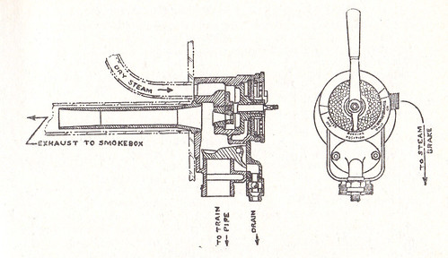 GWR Vacuum Brake Ejector and Application Valve
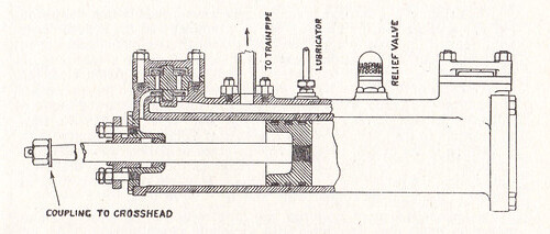
GWR Vacuum Brake Pump

4588 Brake Application Valve. Note small vacuum cylinder above brake valve to proportionally apply the steam brake when the vacuum brake is applied
This brake design with a combination of handbrake, steam brake on the locomotive and vacuum brake on the train remained in use on smaller Great Western locomotives until the end of steam on British Railways. However, tender engines (and certain larger classes of tank engine like the '42XX' and the later '5205' variant) were provided with vacuum brakes on both engine and tender. Vacuum could be created by an ejector controlled by a separate steam cock. A crosshead-driven vacuum pump was also provided. On tender engines, the handbrake operated on the tender wheels only.

'Collett Goods' 3803: A rather steamy view showing the 'straight vacuum' brake valve to the right of the red-painted regulator handle.
On later tender engines, vacuum could be created by both a large and small ejector (combined into a neat fitting mounted on the outside of the firebox just ahead of the cab on the driver's side). A crosshead-driven vacuum pump was also provided. The handbrake, as normal, operated on the tender wheels only.

3205: Handbrake on tender front, fireman's side with water cock for injector on left and vacuum brake vent cock on right.

A Figure from 'The Vacuum Brake and Related Appliances' showing the installation of braking on large GWR locomotives, carriages and wagons.
Click for larger view
Book references
[1] 'An Outline of Great Western Locomotive Practice: 1837-1947' H Holcroft
(Ian Allan)
[2] 'Great Western Steam' by W. A. Tuplin (George Allen and Unwin 1958)
[3] 'The Vacuum Brake and Related Appliances' (The Locomotive Publishing Co)
Pictures
The Great Western Vacuum Brake

4588 Brake Application Valve. Note small vacuum cylinder above brake valve to proportionally apply the steam brake when the vacuum brake is applied
This brake design with a combination of handbrake, steam brake on the locomotive and vacuum brake on the train remained in use on smaller Great Western locomotives until the end of steam on British Railways. However, tender engines (and certain larger classes of tank engine like the '42XX' and the later '5205' variant) were provided with vacuum brakes on both engine and tender. Vacuum could be created by an ejector controlled by a separate steam cock. A crosshead-driven vacuum pump was also provided. On tender engines, the handbrake operated on the tender wheels only.
'Collett Goods' 3803: A rather steamy view showing the 'straight vacuum' brake valve to the right of the red-painted regulator handle.
On later tender engines, vacuum could be created by both a large and small ejector (combined into a neat fitting mounted on the outside of the firebox just ahead of the cab on the driver's side). A crosshead-driven vacuum pump was also provided. The handbrake, as normal, operated on the tender wheels only.

3205: Handbrake on tender front, fireman's side with water cock for injector on left and vacuum brake vent cock on right.

A Figure from 'The Vacuum Brake and Related Appliances' showing the installation of braking on large GWR locomotives, carriages and wagons.
Click for larger view
Book references
[1] 'An Outline of Great Western Locomotive Practice: 1837-1947' H Holcroft
(Ian Allan)
[2] 'Great Western Steam' by W. A. Tuplin (George Allen and Unwin 1958)
[3] 'The Vacuum Brake and Related Appliances' (The Locomotive Publishing Co)
Pictures
The Great Western Vacuum Brake
