London Underground uses a fairly unusual fourth rail electrification system with a nominal voltage of 630 volts direct current (d.c.). At the time the system was being developed, the available insulation materials for traction motors made higher voltages problematic.
Normally, this voltage would be quoted at 'Full Rated Current'. But the current drawn from traction substations varies as trains start, coast, stop. Worst case is generally when two (or more) trains start away at the same time. The trip current on the High Speed Circuit Breaker feeding the positive rail at each sub station should be higher than the normal maximum current expected, otherwise 'nuisance tripping' can occur. But, of course, if a few thousand amps is being drawn by a traction section, there is a voltage drop on the track feed cables and the conductor rails so trains will experience a lower voltage which will change both according to the current drawn by each train and its position of the train in the traction section. The techniques of double end feeding, track paralleling and coupling of adjacent sections mean that a number of rectifiers may be contributing current to a single train. Although Kirchoff's Law allows you to work out the contribution of current from each rectifier, the situation will change second-by-second so, in general, all potential sources of current are paralleled to minimise voltage drop.
The nominal 630 volts d.c. is derived from incoming 11kV or 22kV 50Hz from the grid via transformers and semiconductor rectifier units. Nominal a.c. voltages are subject to variation as the load on the grid varies, also affecting the d.c. traction voltage.

Suite of modern traction circuit breakers (negative breakers at Marlborough Road Traction Sub Station during installation in 2011)

General view of Baker Street Traction Sub Station.
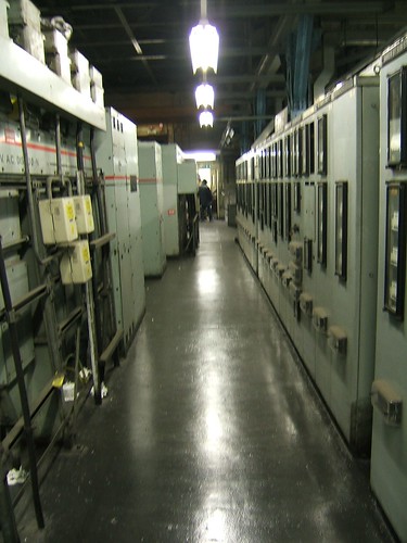
View inside a Acton Traction Sub Station on London Underground.
The fourth rail electrification system is nominally earth-free principally because the materials and construction used in early traction motors were prone to insulation failure introducing an earth. With earth-free distribution, it's possible to continue running if a train develops an earth or partial earth to either the positive or negative side of the supply. But you need to know about it, before a second train develops an earth to the other side and a High Speed Circuit Breaker detects an overcurrent and disconnects the supply.
As described in an earlier article, a potential divider of 220 ohms in series with 110 ohms is installed at the end of each traction sectionalisation to deliberately earth the traction with 220 ohms to the positive rail (outer), 110 ohms to the negative (centre) rail and the connection between the resistors earthed. Applying Ohm's Law to a nominal supply of 630 volts d.c. shows that each resistor takes a current of 1.909 amps and the positive rail sits at 420 volts positive to earth and the negative at minus 210 volts to earth (a 2:1 ratio). These voltages are only true if the 630 volts is nominal - as it goes up and down, the measured voltages to earth will go up and down, too. The voltages are only true if there is no connection to earth other than intentionally via the bleed resistors. In practice, the various spurious paths to earth may unbalance the ratio, offering a fairly simple means of monitoring the section for earth leakage. A system called 'TED' (Traction Earth Detection) is used to display the ratio at the Service Control Centre (formerly called Line Control Centre). If the ratio increases or decreases beyond preset limits, an alarm is automatically sounded to alert the Service Controller.

Traction Earth Detection (TED) equipment at the Metropolitan Line Service Control Centre.
To enable trains to increase demand on the traction distribution system (to support a combination of increased speed, increased service frequency and air conditioning requirements) all new equipment is designed to operate at 750 volts d.c. rather than 630 volts d.c. Operational changes are in progress to implement this change.
Related posts on this website
London Underground and Jan
London Underground: The Waterloo & City Line
Fourth Rail Electrification
London Underground - Traction Power Distribution
My pictures
There's a very patchy collection of pictures showing some of the London Underground lines on my 'Flickr' site (most of them are rather poor, I'm afraid). You can find them all here.
I've placed links to some of these albums below.
The various lines:-
Central Line.Service Control Centres (formerly Line Control Centres):-
White City (Central Line).
District & Circle Line.
Hammersmith & City Line.
Jubilee Line.
Metropolitan Line.
Northern Line.
Waterloo & City.
District Line LCC.Traction Sub Stations:-
Metropolitan Line LCC.
Waterloo & City (combined with general pictures).
Acton TSS.
Baker Street Substation.
Finchley Road TSS.
Marlborough Road Substation.
