But in conditions of poor visibility, such as fog or falling snow, it was realised that the lamp indications needed to be much brighter. Once the lamp indication is visible in all conditions, there is no need for the moving semaphore arm at all. This gave rise to Colour Light Signals which are becoming universal. The semaphore arm (and moving parts) are eliminated and, both by day and by night, the indication is given by various combinations of powerful coloured and white lights. Some cherished techniques from the semaphore era had to be re-designed and electric detection and electric locking largely replaced the mechanical counterparts.
Searchlight signals
The searchlight signal was an early form of colour light with only one lamp, always lit and projecting lens. Different colours were produced by filter pivoted between the lamp and the lens which produced one (more restrictive) colour when an electric solenoid was unenergised and a different colour when the filter was moved by energising the solenoid. The simplest arrangement produced a stop signal (displaying red or green aspect) or a distant signal (yellow or green aspect). Three aspects could be produced by using a polarised solenoid giving 'red' when unenergised, 'yellow' with one polarity applied to the solenoid and 'green' with the opposite polarity applied.
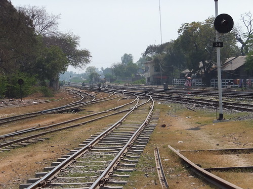
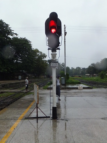
Front view of searchlight signal at Myo Haung, Burma.
Multiple aspect signals
In the U.K., searchlight signals gave way to designs with a separate lamp and lens for each colour where electromechanical relays controlled each lamp. These could be 2-aspect (like the London Underground signal illustrated below), 3-aspect or 4-aspect (described next).
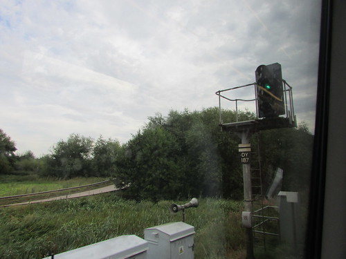
A typical 4-aspect colour light from the 1960s. This is Derby P.S.B. signal DY187 on the Birmingham to Derby line
Click for larger view.
The picture above illustrates the typical features of multiple aspect colour light signals. The platform carrying the signal head is cantilevered to the right of the main post to improve sighting from a distance. For the benefit of the Signal and Telegraph Lineman, a simple handrail is provided around the platform and there is a permanent access ladder. The main post carries an identification plate with the unique signal number (usually first and last letters of the name, here 'DY' for 'Derby' and a number up to 3 digits long). This signal is on plain line with no diverging routes so the signal is arranged to operate automatically, as track circuits become occupied or cleared by the passage of trains. The white top part of the identification plate with a black horizontal bar indicates that this signal is not controlled by the signaller but is an 'Automatic'. However, a telephone is mounted lower down the main post which communicates with the Signaller. The two grey metal cabinets in the foreground are 'Location Cases' containing the necessary signalling relays, cable termination and power supplies. Two loudspeakers are mounted on the top of the smaller location case. This was the, rather crude, 'Staff Location System' of the period. Mobile phones, as we now understand them, were not available in the 1960s (1973 is accepted as the date of the first call on a Motorola mobile phone). Instead, the signaller could send one of four distinctive tones (one for each of three engineering disciplines plus a continuous tone for 'cancel') to the loudspeakers in an area where staff might be. As you can imagine, in built-up areas at night, use of this facility was not very popular with the neighbours.
In this type of multiple aspect colour light signal, four tungsten filament lamps are mounted vertically in line. When lit, each produces 'white' light (with a 'yellow' tinge). Colour filters in front of each lamp provide red, yellow or green light which is concentrated by a lens system on each lamp to project an intense beam towards the approaching trains when the lamp is lit. From the bottom, the four lamps produce red, yellow, green and, at the top, a second yellow. Four different 'aspects' or indications are given - red, yellow, green or 'double yellow' (where both yellow lamps are illuminated, but separated by the unlit 'green'aspect so that the driver can distinguish between 'single yellow - "prepare to stop at next signal" and 'double yellow' - "prepare to stop at next-but-one signal").
The most common repair would be 'replace failed lamp' but this type of low-voltage special bayonet-fitting lamp normally had two filaments.
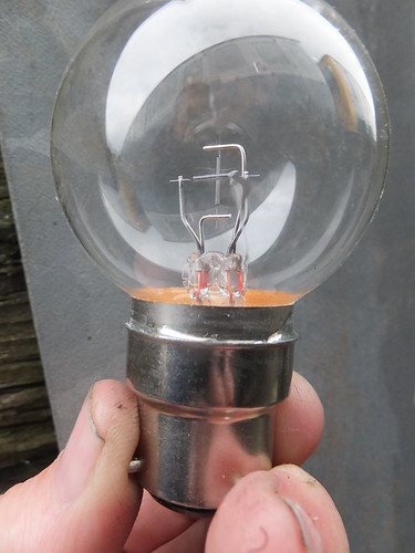
Dual-filament lamp.
Failure of the main filament was detected by a lamp proving relay measuring the current flowing through the filament. Release of this relay upon failure of the main filament switched in the standby filament to keep the signal lit. The failure would be indicated to the Signaller (who, in the 1960s was still called a 'signalman') allowing the lineman to be alerted. Should the second filament fail or the power supply to the signal be lost, the signal would go 'dark'. In this case, the next signal in the rear would automatically be held at 'red' until relays proved that the failed signal should be showing a 'proceed' indication, in which case the signal in the rear would be allowed to display a 'single yellow' to keep trains moving whilst the problem was rectified.
There's more information about this type of signal and the electromechanical relay circuits which typically control them in the (as yet incomplete) series of posts on Princes End Electrical Controls starting here. The following description is taken from the post Princes End Electrical Controls (Part 4).
4-aspect signal head
 Detail of 4-aspect signal head
Each lamp was fed from its own step-down transformer. The primary of each transformer (terminals 1 - 6 on the diagram above) was fed, via control relay contacts in the adjacent location case, with nominal 110 volts a.c.
The signal lamps were dual-filament low-voltage special bayonet-fitting type. Note that the 'Auxiliary' filament was fed from a lower voltage than the 'Main'. Each 'Main' filament was in series with a lamp proving relay mounted in the signal head ('ER1' to 'ER4'). If current was being drawn by the 'Main' filament, the appropriate lamp proving relay was energised and the 'Auxiliary' filament was disconnected. Release of the lamp proving relay connected the 'Auxiliary' filament via a normally closed ('back') contact.
Further contacts on the lamp proving relays were wired to indicate the status of the 'Main' filaments (terminals 7 - 9 on the diagram above). The contact circuit is drawn rather oddly but the effect is that the signal head presented a closed circuit between terminal 7 and terminal 8 (which was linked to terminal 9 externally) provided any of the relays 'ER1', 'ER2', 'ER3' were energised. The indication contact on 'ER4' (the second Yellow lamp used for the 'HH' 'Double Yellow' Aspect) could be shorted out by an external link when not used.
The signal head was a rectangular die cast box closed by a hinged door at the rear secured by a padlock. The front of the head had four apertures fitted with projecting sheet steel hoods to minimise the effect of overhead sunlight. Each aperture had a clear cast glass lens (the colour filtering was behind this lens). To project an intense beam visible at a distance, a Fresnel lens was used where the rear of the lens was shaped into a series of stepped rings. Because the Fresnel is so efficient at projecting light in a narrow beam, it could be difficult for a driver stopped close to the signal to confirm the aspect. In early signals of this type, a small second aspect was provided aligned to face a train waiting at the signal. This aspect was also provided with a small hood. Because of the shape of this hood, the device was often called the "pig's ear".
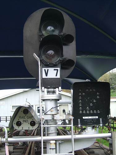
London Underground Signal Training facility, Bollo Lane, Acton: 2-aspect colour light signal with "pig's ear" aspects and 'theatre type' (multilamp) route indicator on the right capable of displaying '1' or '2'. Rail Gap Indicator on the left indicating section ahead discharged when lit.
However, by the 1960s, a simpler arrangement was in use. The section of cast glass Fresnel Lens between around 'four o'clock' and 'five o'clock' intentionally had a different profile, which deliberately scattered light towards a waiting train, rather than projecting it forward as part of the main beam.
The signal head was then mounted in a variety of ways, so as to give the driver the best possible 'sighting' of the signal. Straight tubular posts, brackets, massive cantilevers or gantry bridges were used, depending upon the geography.
Use of Light Emitting Diodes (LEDs)
To improve the reliability of signal lamps, replacement lamps were produced using multiple LEDs packaged as a plug-in replacement for a filament lamp.
Signal 'R101' on Platform 2 at Yangon, Burma. A multi-LED lamp has replaced the original filament lamp.
The availability of very high light output LEDs has led to various manufacturers producing a range of modern equipment, some of which is barely-recognisable as railway signals.

LED 4-aspect signal at Wolverhampton. Note the small, red indication projected sideways - the modern "pig's ear". Position light subsidiary aspect.
Related Posts on this Website
Railway Signalling in Britain (Index).
Princes End Electrical Controls (Part 1).
My Pictures
2-aspect colour light signal head.
Photographs may be selected, viewed or downloaded, in various sizes.
