Each signalman is responsible for monitoring the signals he controls. In a previous part of this series (Part 4 - Semaphore Signal Aspects by Night) I outlined how some signals leading to the advance section were visible to the signalman from the front whilst the use of 'Backlights' allowed the signalman to confirm that some signals in the rear of his box were displaying a 'Stop' aspect. But not all signals could be observed by the signalman like this. In particular, the all-important Distant signals were generally not visible from the signal box.
Just as electrical techniques were adopted by railways to create the Block System, electricity offered methods of repeating the aspect shown by a signal back to the signal box and proving whether the signal lamp was lit.
1. SIGNAL ARM REPEATERS
Detecting the Arm Position
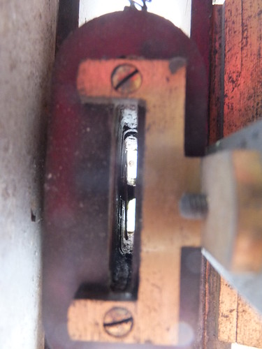
The signal arm was coupled to an electrical contact box fixed to the signal via a solid rod. As the arm moved, a moveable contact in the contact box moved between two fixed contact. Depending upon the type of contact box, the moveable contact had linear or rotary motion. In each case, one contact was closed with the arm 'On', the other contact was closed with the arm 'Off'. In between 'On' and 'Off', no contact was made and the signal aspect was described as 'Wrong'. By providing an electrical supply at the signal location, the contact box could connect a direct current to a repeater wire taken back to the signal box. The return for this direct current was via the earth, usually with a bond to one of the running rails. The connections were arranged so that, with the signal arm 'On' one polarity would be connected to the repeater wire, with the signal arm 'Off' the opposite polarity would be connected. With the signal arm in an intermediate ('Wrong') position, neither polarity would be connected to the repeater wire.

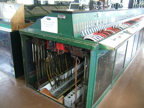
Western Region pattern linear contact box with cover removed and displayed as a working demonstration (Exeter West box, Crewe).
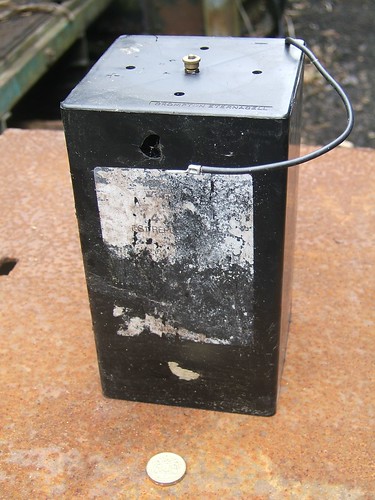
During steam days, there was rarely electric power available trackside so batteries (normally primary cells with large capacity) were provided, typically mounted in a battery box at the side of the track near the signal post.

Typical battery used on railways (One pound coin for scale).
Transmitting the Arm Position to the Signal Box
In general, electrical circuits on railways (whether for telegraph, telephone, block signalling or signal repeating) were carried on an 'Open Wire' route as bare copper wires strung between porcelain insulators mounted on the cross-arms of a series of 'telegraph poles' extending alongside the railway. The repeater wire from a signal would join the main 'Open Wire' route either as a bare wire connected to a porcelain insulator on the signal post or as an insulated cable. The 'Open Wire' route was then used to lead the repeater wire back to the supervising signal box.
Indicating the Arm Position to the Signalman
At the signal box, current of one polarity in the repeater wire represented 'On', current of the other polarity represented 'Off' and no current implied the signal was 'Wrong'.
Indication was made using a galvanometer where the repeater wire current passed through an electrical coil with a slot arranged through the middle. A small metal 'flag' was mounted in the slot on a pivot so as to swing to the left or right of the 'rest' position under the influence of the magnetic field produced when the associated signal was 'On' or 'Off' and a current flowed through the repeater wire. The direction of movement of the 'flag' depended upon the polarity of the current. The pivot extended through the front plate of the indicator so as to turn the miniature signal arm on the front of the indicator as the current moved the 'flag'.

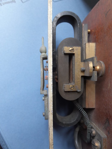
An early signal repeater viewed from the right with the wooden case removed. Left to right: Cast metal model signal post and miniature signal arm visible to signalman, metal front plate, oval mounting bracket, electrical coil (note slot), wooden backplate.
Close-up of the electrical coil showing the slot and the pivoted metal 'flag' which deflected under the influence of the magnetic field so that the position of the miniature signal arm corresponded with the actual signal arm being repeated.
In early indicator designs, the galvanometer was mounted in a glass-fronted wooden cabinet which was fixed near the lever controlling the repeated signal. More modern indicators were more compact, in a circular glass-fronted housing simply screwed to the front of the block shelf so as to be readily visible to the signalman.
Examples of Signal Arm Indicators
Typically, indicators had a model of a signal, with the miniature arm moving up or down to indicate 'Clear', according to the design of the actual signal being repeated.

Upper-quadrant Distant Signal Arm Repeater in a round case (Displayed at Shackerstone Railway Museum).

Signal Arm Repeater for a lower-quadrant stop signal. Here a round case has been mounted in a wooden box to allow fitting where there is no block shelf (Part of a display at Exeter West box, Crewe).
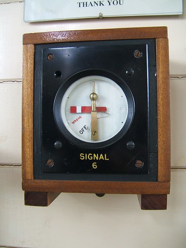
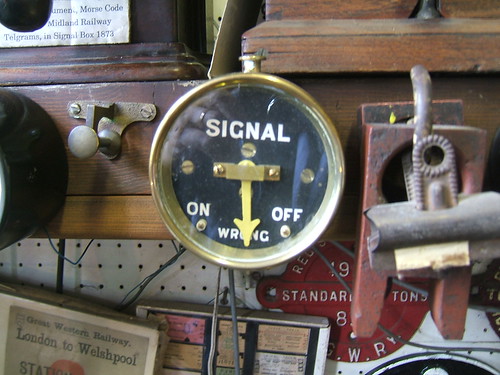
Sometimes, there was no attempt to model a signal post, but the paint scheme of the miniature arm would reflect the full-size signal.

Signal Arm Repeater intended for use with a Subsidiary Signal - showing 'Wrong' (In use at the Battlefield Line).

Signal Arm Repeater intended for use with a Subsidiary Signal - showing 'On' (In use at the Battlefield Line).
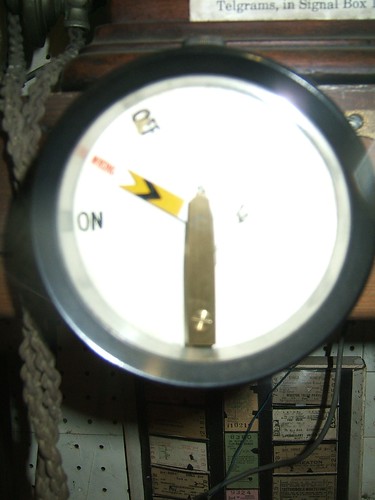
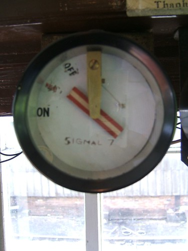
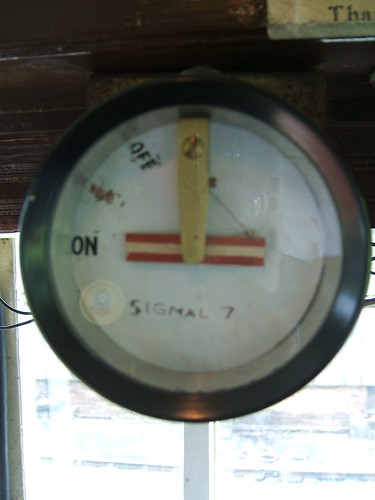
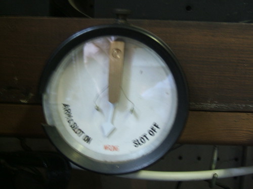
A more abstract display featured a simple pointer. In the example below, the pointer is painted yellow to indicate its use on a Distant Signal. This type of indicator with a pointer was also used where a lever controlled a colour-light, rather than a semaphore, signal.
 A Signal Arm Repeater with a yellow pointer, rather than a signal model. The round case is metal (Displayed at Shackerstone Railway Museum).
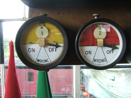
The two indicators below have the upper half of the front plate painted to represent the signal type. In this case, round engraved labels fitted inside the case neatly identify the controlling lever but identification was often by an external engraved label mounted adjacent to the indicator.
 Signal Repeaters mounted on Block Shelf (Lever 1, Up Distant, Lever 2, Up Home at Exeter West box, Crewe).
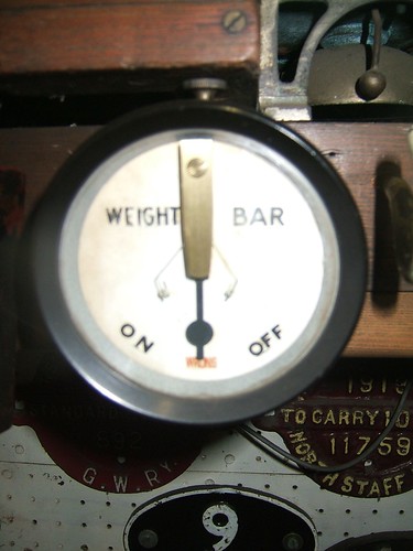
Where a lever controlled a slot (for instance, a distant signal mounted under a stop signal controlled by another box), the position of the weight bar, not the arm, was repeated and the pointer was shaped to represent the weight bar.

Weight Bar Repeater for slotted signal (Displayed at Shackerstone Railway Museum).
However, if the slot was associated with a Stop signal, it was sometimes necessary to give assurance to the signalman that the signal arm (not just the slot) was correctly 'On'. Contact boxes were fitted on both the arm and the weight bar and inter-wired as necessary.
 In this case, the Repeater can indicate that not only the Weight Bar (Slot) is 'On' but that also the associated signal arm is actually 'On' (Displayed at Shackerstone Railway Museum).
2. SIGNAL LAMP REPEATERS
Pyrometers
Paraffin signal lamps were normally continuously lit. The hot air produced by the small flame rose through the chimney at the top of the lamp housing. The Pyrometer was a device fixed in the hinged lid of the housing so that the hot air passed over it, closing an electrical contact. If the flame became extinguished, the electrical contact opened.
Metals expand when heated. The measure of how much each metal expands is called its Coefficient of Linear Expansion. A Bimetal strip is made of two metals with markedly different coefficients of expansion alloyed together. If such a strip is mounted with one end clamped and the other free, when it is heated, the strip will bend away from the metal with the larger coefficient of expansion. This movement of the strip when heated can be used to close an electrical contact. This is the principle used by simple thermostats.
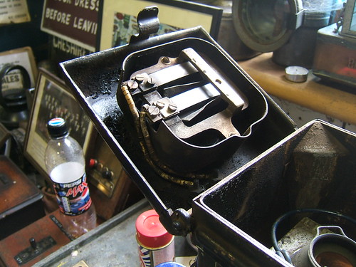
The picture below shows one design of pyrometer used in signal lamps. The mounting frame is in the form of a ring. Two bi-metal strips are clamped to the frame at one end only, electrically insulated from the frame. The strips extend across the ring so as to be exposed to the rising hot air. When the bimetal strips are heated, they deflect and make contact with a bridging piece also mounted on the frame but insulated from it. Two flexible bare copper wires are attached to the fixed ends of the bimetal strips, insulated by porcelain 'beads' threaded onto the wires. The two wires lead to two substantial insulated electrical terminals mounted on the hinged top of the lamp housing. Provided the lamp is burning, there is electrical contact between the two insulated electrical terminals mounted on the lamp housing. If the lamp is extinguished, the bimetal strips cool and move away from the bridging piece, breaking the electrical circuit.
 Close-up of a Pyrometer mounted in the hinging top of a lamp housing (Displayed at Shackerstone Railway Museum).
Electrical batteries were provided at the signal location so that the pyrometer could connect a direct current to a lamp repeater wire taken back to the signal box, provided the lamp was lit. The return for this direct current was via the earth, usually with a bond to one of the running rails. On signals with more than one arm, it was possible for two or more pyrometers to be wired in series so that an alarm was given if any of the group of lamps was 'Out'.
Transmitting the Lamp Status to the Signal Box
The arrangements for transmitting lamp status were exactly as described above for 'Transmitting the Arm Position to the Signal Box'
Indicating the Lamp Status to the Signalman
At the signal box, current flowing in the lamp repeater wire represented 'Lamp In', no current represented 'Lamp Out'. Indication was made using a galvanometer similar to that described above for 'Indicating the Arm Position to the Signalman', except that it had only two positions, not three. To quickly alert the signalman to a lamp failure, the 'Lamp Out' indication would sound a bell or buzzer until the signalman acknowledged the alarm by operating a switch.
Early indicator designs featured glass-fronted wooden cabinets (as for Signal Arm Repeating), fixed near the lever controlling the signal being repeated. This eventually evolved into a modular system, outlined below.
Examples of Signal Lamp Indicators

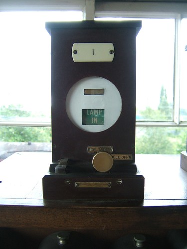
Great Western Lamp Repeater in wooden case. Note the switch to silence the alarm (Lever 1, Up Distant, at Exeter West box, Crewe).
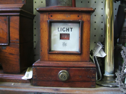
 Midland Railway Lamp Repeater in wooden case. Note the Midland Wyvern and letters 'M.R.' (Displayed at Shackerstone Railway Museum).
As more signals were equipped with lamp repeaters, the need for a more compact arrangement for displaying lamp status was met by a modular system. The picture below shows the lamp repeater for Bloomfield Junction which was the simplest possible form, comprising a common Test/Buzzer unit with a larger 2-circuit display unit mounted on top. More complex installations required one common unit plus a number of 2-circuit display units bolted together. Normally, indicator lamps were out and there was no buzzer alarm. The indicator lamps could be tested by pressing the test pushbutton on the common unit. Failure of a signal lamp would light the appropriate indicator lamp and sound the buzzer. The buzzer was silenced by operating the toggle switch next to the lit lamp to the 'B' position. When the signal lamp was restored, the buzzer would sound until the toggle switch was placed in the 'A' position.

Modular Signal Lamp Repeater used by British Railways (10p coin for scale).
3. COMBINED SIGNAL ARM AND LAMP REPEATERS
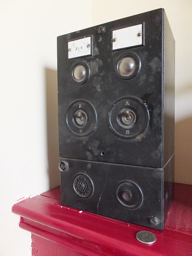
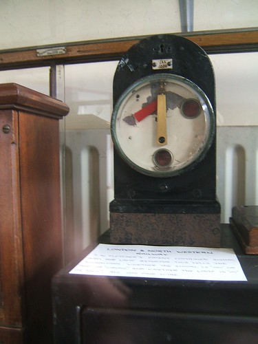
J. W. Fletcher patented a combined signal arm and lamp repeater which was used on the London and North Western Railway. Only one wire was needed between the signal and signal box, rather than two (one for arm repeating, one for lamp repeating). Despite this advantage, more modern installations usually adopted the 2-wire approach.
The signal arm detection operated in the manner described in section 1 above. Failure of the signal lamp placed a resistance in series with the repeater wire, restricting the current flowing. The galvanometer repeating the arm position was designed to be sufficiently sensitive to carry on working correctly on the reduced current but a second galvanometer controlling the Lamp In/Lamp Out display window was designed to show the 'Lamp Out' condition with the reduced current. When the signal lamp was restored, the pyrometer contact would short out the resistor and the increased current caused the display window to show 'Lamp In'.

Fletcher's Arm and Lamp Repeater (displayed in Crewe Heritage Centre) only required one wire from the signal to the signal box.
4. INDICATORS USED FOR OTHER PURPOSES
2-position and 3-position indicators were used for various other purposes. The examples given below are not exhaustive.
2-position indicators were also used, for instance, to show that at electrical release was available at a Ground Frame.
 Indicator for remote electrical release on a set of mechanically-operated points side-by-side with an Arm Repeater for an Upper Quadrant Stop Signal (displayed in Crewe Heritage Centre).
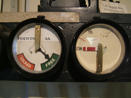
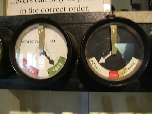
The picture below shows a 2-position indicator used to show whether a remote electrical release was available. This is side-by-side with a 3-position indicator used to repeat the position of a set of points provided with Electrical Detection.
 Indicator for remote electrical release on a set of mechanically-operated points and Repeater for a set of points with Electrical Detection (displayed in Crewe Heritage Centre).
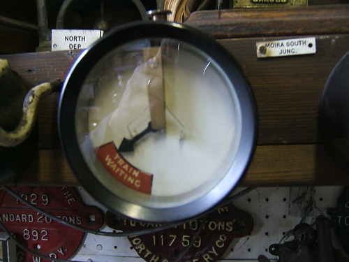
Before track circuiting was common, a 'Fireman's Call Plunger' was sometimes provided to alert the signalman to a train detained at a signal. A 2-position indicator was used to remind the signalman of the waiting train. The indication was cancelled when the signal was cleared, allowing the train to proceed.
 'Train Waiting at Signal' Indicator (Displayed at Shackerstone Railway Museum).
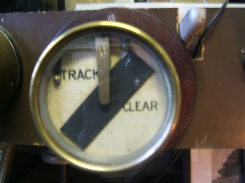
Even when track circuiting was installed, it was frequently done piecemeal. If only a few track circuits required indication to a signalman, they would normally be indicated to the signalman by a series of 2-position indicators provided with a distinctive black bar which moved through 45 degrees. The black bar was horizontal when there was no current through the galvanometer (representing 'Track Occupied').
 Track Circuit Indicator showing 'Track Clear' (Displayed at Shackerstone Railway Museum).
My Pictures
There are pictures of signalling equipment in various sets and the links below are not exhaustive:-
Shackerstone Railway Museum.
Signalling at Peak Rail.
British Railway Signalling Equipment.
Exeter West Signal Box.
Signalling Displays at Crewe Heritage Centre.
More
Go to Part 6 - Mechanical Operation of Points
[Link to Part 6 added: 18-Sep-2014]
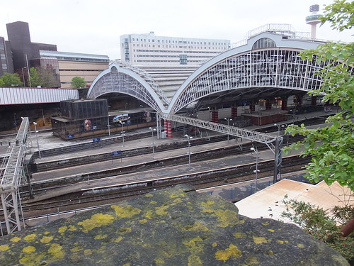 Lime Street: the Train Sheds viewed from the car park off Lord Nelson Street.
 Click for larger image.
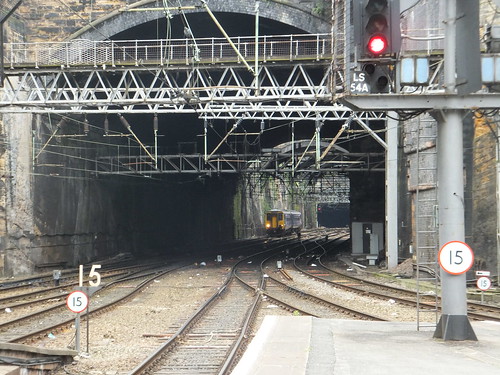
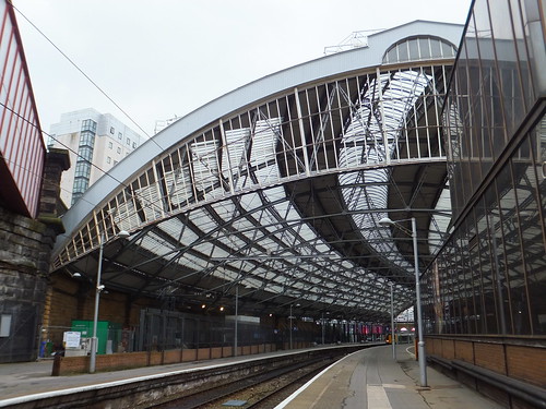 Liverpool Lime Street on 19th May 2012. View westward towards the buffers on Platform 8 with 4-car EMU 350 115 (almost hidden) ready to leave for Birmingham New St.
 Alfred Waterhouse's French renaissance frontage masks William Baker's north train shed.
 View of the road frontage of the south train shed.
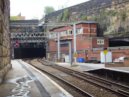
 Lime Street: Looking towards Edge Hill from Platform 7 with a DMU approaching the local platforms on the north side of the station.
 The 'A.R.P.' style signal box at Liverpool Lime Street in May 2012. The route is set for a departure from Platform 9 to the Up Fast.


