Introduction
The Liverpool and Manchester Railway opened in 1830 with the original passenger terminus at Crown Street, Edge Hill. First Class passengers were provided with a horse-drawn carriage service between Crown Street and Dale Street, near the commercial centre of the city. From Edge Hill, there was also an inclined tunnel just over 2 km long cut through sandstone, shale and clay to Park Lane Depot near Wapping Dock. Locomotives were initially prohibited from this tunnel so passenger and goods trains descended to Park Lane by gravity, controlled by Brakemen on the train. Trains were hauled back up to Edge Hill by rope, using stationary steam winding engines.
The success of the railway meant that the initial arrangements proved inadequate and in 1837 another tunnel was cut from Edge Hill to a new station in Lime Street. Crown Street was retained as a goods depot. The tunnel to Lime Street was just over 2 km long, inclined at a gradient of around 1 in 93 and principally through sandstone. Further winding engines were provided at Edge Hill (together with a new station) and the approach to Lime Street was rope worked from 1837 until 1879 when locomotives started working through to Lime Street.
After a short period of locomotive working, the tunnel was opened-out into a deep rock cutting, spanned by numerous bridges to carry the various roads - see my post here.
Edge Hill Station
When the original Liverpool and Manchester line was extended from Edge Hill to Lime Street station in 1837 a new station was built at Edge Hill, initially with two platform faces, later with four. The buildings survive to the present and are discussed in book reference [9]. Oddly enough, the modern Edge Hill Power Signal Box is also covered in this architectural book.
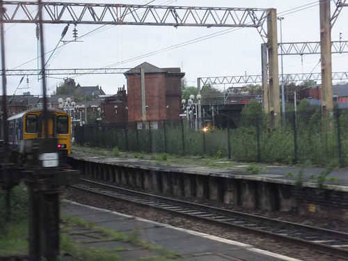 A modern view of Edge Hill station, looking towards Liverpool Lime Street,
Edge Hill Grid Iron
By 1873, the volume of freight being dealt with was becoming embarrassing. 'Outwards' traffic passing through Edge Hill had risen from a quarter of a million tons in 1850 to over a million tons in 1873 but, in the same period, siding capacity had only increased from 1,782 wagons to 3,215 wagons leading to severe congestion. Mr. H. Footner of the L.N.W.R. prepared an ambitious scheme for marshalling freight trains using gravitation which was implemented and brought into use in 1882. In 1889 Sir George Finlay described the arrangements in his book 'The Working and Management of an English Railway' (this interesting book is available to read online here). His description reads:-
"In addition to the want of room, the main passenger lines had to be crossed every time wagons were moved from one group of sidings to another (and there were a great many groups), so that there were serious obstacles to be encountered in carrying on the working, and as the safety of passenger trains always had to be the first consideration, the goods traffic often had to suffer delay. The company had, at that time, about 70 acres of spare land on the north side of the railway, and available for extension, but to reduce this to the level of the main lines would have involved a stupendous amount of excavation, and the fact that the surface of the land rose from West to East, and that, for a comparatively reasonable outlay, sidings could be laid upon it on an uniform which would enable them to pass over the branch line running round to the docks, which branch line intersected the land, suggested to Mr. Footner a scheme for marshalling by gravitation. In considering a scheme of this kind two things appeared to be essential - first, that in the passage of the trucks from the top to the bottom of the incline, all the necessary changes in their relative positions should be effected, so that when they reached the bottom they should be ready to go away as properly marshalled; and secondly, that there should be some means of stopping, without injury to them or their loads, any trucks which might get beyond the control of the shunters. The mere principle of shunting by gravitation was no new thing, as it had already been successfully adopted for coaling ships on the Tyne and for sorting mineral trains at Darlington on the North-Eastern Railway; but Mr. Footner claims as his own the idea of an inclined plane specially constructed in such a way as to sort and marshal a mixed goods train by gravitation alone, without any assistance from locomotive or horse power. The sidings consist of, the six upper reception lines at the summit of the incline, holding 294 wagons; secondly, the sorting sidings, 24 in number, capable of holding 1,065 wagons, into which the wagons, when separated, first run, each siding receiving the wagons for a particular train; thirdly, two groups of marshalling sidings, which, owing to their peculiar formation, have been christened 'grid-irons', through which the trucks are filtered so as to make them take their proper order of precedence in the train; and fourthly, the lower reception and departure lines, which receive the trains in their complete state, and where the engines are attached to take them away. The modus operandi is as follows:- On the arrival of a set of wagons in the upper reception lines, the rear brakes are put on, the engine is detached, and then on each wagon is chalked the number of the sorting siding it has to enter. One man carefully inspects the brakes of each wagon, and calls out the chalked number to the second man standing below him, who has to regulate the speed of the descending wagons; this second man passes the number on by hand signal to the shunter lower down who has charge of the points, and who, by moving a lever, turns the wagon into its proper siding. The shunters are provided with brake sticks, which they insert between between the wheel and the wagon frame to steady the wagons in going down, and they also use these implements for letting down the brake levers when required. By the process thus described, each sorting siding now holds a separate train, although the wagons composing it are in indiscriminate order, but by a repetition of the operation the wagons of each train are separated in the gridirons and are lowered, one by one, in to the departure lines, in the precise order in which they are required to be sent away."There is a 1:1800 scale model of the Edge Hill Gridiron in the National Railway Museum (NRM object 1975 8107). The model is mounted in a glazed oak desk case and originally formed part of the LNWR exhibition collection.

The model of the Edge Hill Gridiron. The line from Liverpool to Manchester runs (l-r) across the middle of the photograph, with the blue-roofed Edge Hill Engine Shed on the left and the rock cutting at Olive Mount on the right (Photo: Roger Henry).
By the 1890s, the complex of lines around Edge Hill had more-or-less reached their zenith and they survived, remarkably intact, until the wholesale destruction of the facilities in the 1960s, for which we can largely thank the cargo-handling revolution brought about by the containerisation of ships' cargoes.
Book reference [7] includes various maps of Liverpool's railways and a diagram showing the layout of the Grid Iron. There's also a diagram of the Grid Iron (including gradient information) in book reference [4].
Edge Hill around 1890
Here's an incomplete, simplified, not-to-scale sketch of the lines around Edge Hill below. An explanation of the letter references on the sketch is given in the table below the sketch.
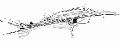 Click for larger image..
Simplified sketch of Edge Hill and the Grid Iron around 1890.
| Ref | Description |
| A | Wapping Up and Down Goods (the original route to the Docks, initially cable worked. Bank Head Signal Box [not shown] stood adjacent to the Edge Hill tunnel entrance). |
| B | Crown Street Up and Down Goods (this later double-track route replaced the original single-track approach). |
| C | Lime Street Down Slow, Down Fast, Up Fast, Up Slow. |
| D | Waterloo Up and Down Goods (this second route gave access to the 'downstream' docks as the port expanded). |
| E | Spekeland Road Coal Wharf. |
| F | Down Sidings. |
| G | Carriage Shed. |
| H | Edge Hill Station. |
| J | Waterloo Tunnel Mouth Signal Box. |
| K | Edge Hill Goods Depot. |
| L | Warehouse. |
| M | Edge Hill No. 2 Signal Box (Edge Hill No. 1 [not shown] stood on a bridge structure over the Up Slow at the Lime Street end of Edge Hill station until 1947). |
| N | Edge Hill No. 16 (Picton Road) Signal Box. |
| P | Edge Hill No. 14 Signal Box. |
| Q | Edge Hill No. 10 Signal Box. |
| S | Park Sidings (No. 20) Frame. |
| T | Exhibition Junction (No. 13) Signal Box. |
| U | Lower North Grid Sidings. |
| V | Upper North Grid Sidings. |
| W | North Grid. |
| X | Lower South Grid Sidings. |
| Y | Upper South Grid Sidings. |
| Z | South Grid. |
| AA | Wagon Shop. |
| AB | Edge Hill No. 3 Signal Box. |
| AC | Edge Hill No. 4 Signal Box. |
| AD | Edge Hill No. 12 Signal Box. |
| AE | Edge Hill No. 11 Signal Box (Engine Shed Junction). |
| AF | 60-foot Turntable. |
| AG | 40-foot Turntable. |
| AH | Tuebrook Sidings. |
| AJ | Edge Hill No. 5 Signal Box. |
| AK | Edge Hill Engine Shed. |
| AL | Rathbone Road Yard. |
| AM | Up and Down Circular Goods. |
| AN | Up and Down North Lines (to Manchester). |
| AP | Up and Down South Lines (to Manchester). |
| AQ | Olive Mount Junction Signal Box. |
| AR | Up and Down Bootle Lines. |
| AS | Gridiron Feed Lines. |
| AT | Top of Grid Frame (No. 19). |
| AU | Pighue Lane Signal Box. |
| AV | Edge Lane Junction Signal Box (to Bootle, serving the most downstream docks). |
| AW | Upper Reception Sidings. |
| AX | Tunnel Road. |
| AY | Picton Road overbridge. |
| AZ | Wavertree Junction Signal Box (to Ditton, Runcorn and Crewe). |
Edge Hill Engine Shed
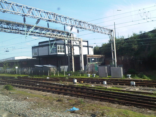
Whilst much of the freight infrastructure around Edge Hill remained tantalisingly inaccessible, the locomotive depot at Edge Hill, squeezed into the angle between the Manchester and Crewe Lines, was clearly visible from passenger trains passing on either route. The book 'LMS Engine Sheds: Vol 1 The L&NWR' [reference 6] has detailed information on the shed and its allocation of locomotives. A new coaling plant was built in 1914, with three 40-ton bunkers, using the 'Hennibrique System' of ferro-concrete construction.

The coaling plant at Edge Hill. The inclined line on the extreme left goes to Engine Shed Junction and formed one of two ways on and off shed (Photo: Edge Hill Archive).
Signalling
My earlier post Liverpool Lime Street Station discusses the power box introduced at Lime Street with colour light signalling. Around Edge Hill manual signal boxes remained, as indicated on the sketch above. Edge Hill No. 1 (at the Lime Street end of Edge Hill station, on a bridge structure over the Up Slow) was abolished in 1947. The signal boxes were London and North Western pattern (although Exhibition Junction appears to have been an L.M.S. composite pattern with a hipped roof). There were some upper-quadrant L.M.S. signals but an amazing number of London and North Western lower-quadrants survived into the 1960s. The section 'Track Diagrams' below has details of the Signalling Record Society publication including these signal boxes. The 'NX' signalling panel at Edge Hill, introduced in the 1960s, abolished a number of the Edge Hill manual boxes, but some lasted until the 1970s.
External links
Liverpool and Manchester Railway (Wikipedia).
London and North Western Railway (Wikipedia).
London, Midland and Scottish Railway (Wikipedia).
Pictures of Exhibition Junction by edgehillsignalman.
Edge Hill Archive
Book References
[1] 'The Style L Power Frame' written and published by J. D. Francis 1989 (ISBN 0 9514636 0 8).
[2] 'Liverpool & Manchester Railway 1830-1980' by Frank Ferneyhough published by Book Club Associates.
[3] 'A Regional History of the Railways of Great Britain': Volume 10 The North West by G. O. Holt, Second Edition published by David & Charles (ISBN 0946537 34 8).
[4] 'North Western: A Saga of the Premier Line of Great Britain: 1846-1922' by O.S. Nock published by Ian Allen in 1968 (SBN 7110 0016 6).
[5] 'The History of the London and North Western Railway' by Wilfred L. Steel published by "The Railway and Travel Monthly" in 1914.
[6] 'LMS Engine Sheds: Vol 1 The L&NWR' by Hawkins and Reeve published by Wild Swan Publications (ISBN 0 906867 02 9).
[7] 'An Illustrated History of Liverpool's Railways' by Paul Anderson, published Irwell Press (ISBN 1-871608-68-6).
[8] 'Pre-Grouping Railway Junction Diagrams 1914', published by Ian Allen (ISBN 0 7110 1256 3).
[9] 'The Buildings of England - Lancashire: Liverpool and the South-West' by Richard Pollard and Nikolaus Pevsner, published by Yale University Press (ISBN 0 300 10910 5). This book may be previewed here.
Track Diagrams
You can find detailed signal box diagrams for the numerous signal boxes around Edge Hill in the excellent series of publications from the Signalling Record Society 'British Railways Layout Plans of the 1950's'.
Edge Hill area is included in 'Volume 9: LNW Lines Crewe to Euxton Junction, Liverpool to Manchester (and associated branches)' (ISBN: 1 873228 11 2).
For details of what remained around Edge Hill in 2005, refer to 'Railway Track Diagrams Book 4: Midlands & North West', Second Edition, published by Trackmaps (ISBN: 0-9549866-0-1).
Related articles in this Blog
Edge Hill Cutting.
Liverpool Lime Street Station.
'Black 5' to Birmingham.
My Pictures
Liverpool: The City.
Liverpool Area Railways.
