The turntable (or 'turnplate') appeared early in the development of railways, initially as a means of routing single wagons from one line to another at coal mines and similar installations and often narrow-gauge.
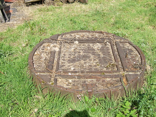 A cast narrow-gauge wagon turntable preserved at Black Country Living Museum (without the approach tracks).
When the first steam railways were built, the size of turntables was increased to allow shunting of passenger coaches and turning of the small locomotives then in use. No passenger station lacked a battery of turntables to assist in marshalling each train. The 'Roundhouse' design of locomotive shed using a turntable to access a number of radiating stabling roads was used as early as 1846 by the London and Birmingham Railway (there's a very brief description of that line here). The building of the roundhouse locomotive shed built at Camden survives as a Grade II* listed building and is now used as a performing arts and concert centre called Roundhouse. There are brief details of the building on Jack Whitehead's Local History website here.
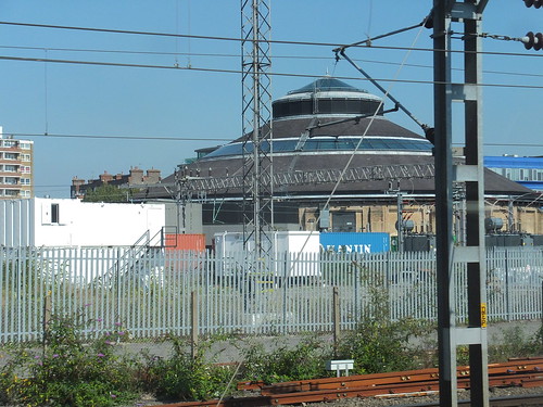 Camden, showing the London and Birmingham locomotive roundhouse of 1846 (now the Roundhouse Theatre).
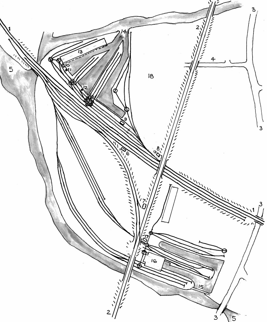
Eventually, small turntables became confined to goods yards and canal interchanges. They were often provided in large numbers, sometimes associated with capstans so that haulage ropes could be arranged allowing horses to move the wagons. The sketch map below shows the sidings and wagon turntables at the canal interchange basins at Bloomfield in the West Midland area of England in the early years of the 20th century.
 A larger version of this sketch can be found here.
There's a brief write-up about the canals and sidings at Bloomfield in the post Rail and Canal at Bloomfield.
The picture below shows a typical standard-gauge wagon turntable, this one preserved in Birkenhead Docks.
 Birkenhead: Wagon Turntable adjacent to Duke Street Lifting Bridge.
There's a write-up of my exploration of Birkenhead's Docks in the post Birkenhead and New Brighton by train (Part 2).
LOCOMOTIVE TURNTABLES
Developments in locomotive design produced larger engines which required longer turntables. In Britain, turntables up to 70 feet in length were made. There's a Wikipedia article here.
The following description is based on an article published in The Locomotive Magazine and Railway Carriage and Wagon Review, dated 15th February 1937. This article, in turn, was 'a brief abstract of the main points mentioned' in a paper on Locomotive Turntables read to a meeting of the Institution of Mechanical Engineers on 27th January 1937 by Associate Member Mr. J. H. A. Wilkins.
Modern locomotive turntables conform to one of three types:-
1. The cantilever, or centre balanced type: either 'through' or 'deck' pattern.Of more than 900 turntables in use in 1936, most were centre-balanced type with only around 20 ar and 20 of the continuous girder (Mundt) pattern. In the U.K, the largest turntable in use is 70 ft. diameter.
2. Articulated or centre hinged type.
3. Continuous girder type supported at three points (Mundt type).
1. Cantilever or centre balanced type supported on the centre pivot
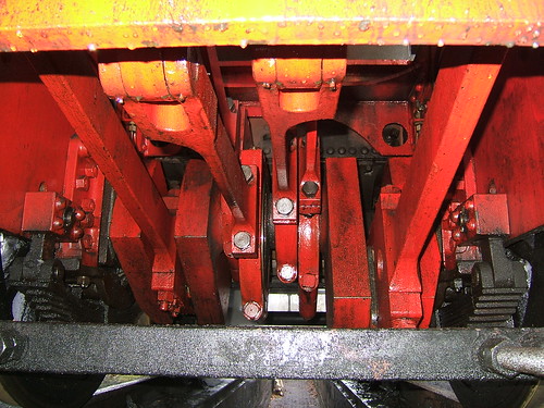
The turntable is balanced in the centre, the main girders acting as cantilevers. Two strong wrought iron or steel plate main girders are braced together by stretchers and securely attached to a middle framework which rests on and revolves around a centre pin fixed to a solid foundation. Large carrying wheels which travel on a rail laid round the circumference of the pit are attached to both ends of the main girders.
In use, the locomotive to be turned is centred or 'set' so that the majority of the weight is taken by the centre pivot, and a small force applied to the ends of the main girders is able to turn the table. To assist in achieving the necessary balance, the length of the table should be several feet longer than the wheel base of the locomotive.
During erection, the large carrying wheels are given a slight clearance from the circumferential rail and carry that part of the weight not supported by the centre pivot.
If a locomotive is perfectly balanced, all the weight is carried by the centre pivot, otherwise part of the weight is supported by the large carrying wheels at one end of the turntable.
The centre pivot comprises a cap or yoke cast in steel which supports the main girders by large suspension bolts. The cap rests on a pivot bearing, typically made of 'UBAS' case hardening steel supporting a bronze, gun-metal, or steel cup ('UBAS' was a trade mark used by W. T. Flather who manufactured special steels). If an anti-friction thrust bearing is incorporated, this is enclosed in a steel housing resting on, and positioned on, the stump or centre pivot. The centre pivot takes the full load of the turntable and locomotive when in use and is usually cast iron, secured by rag bolts or similar to a solid, normally concrete, foundation.
Because of the clearance given to the large carrying wheels, 'blocking pads' are provided to take the weight of the locomotive when running on or off the turntable. In some cases the hand lever for operating these blocking pads also operates the locking bolts for holding the table in position opposite the various roads radiating from the pit. In its horizontal position this lever is sometimes used for turning the table manually.
In some designs, levers to operate the blocking pads and locking bolts are replaced by hand wheels at each end of a shaft running the whole length of the turntable girder, so that turning the hand wheel at either end operates the blocking pads and locking bolts at both ends. The locking bolts also serve as blocking pads in some designs, engaging in a cast iron locking rest fixed in the pit wall where each track radiates.
The centre-balanced main girder may be of 'deck' (under girder) or 'through' (over girder) design.
In the 'deck' type, the rails are laid upon the top of the main girders, simplifiying construction but requiring a deep pit to accommodate the height of the main girders.
In the 'through' type, the rails are laid between the main girders, carried on cross members. This allows the use of a shallower pit. The G.W.R. normally use the 'through' type in outside locations (a 65 ft. turntable on the GWR at Oswestry was cited as an example) where a notice visible to the engineman reads "All engines must stop before going on to the turntable." so as to avoid shock as the locomotive runs on to the table, due to the clearance on the large carrying wheels). The 'through' type, although possessing the advantage of requiring only a shallow pit, weighs considerably more itself due to the heavier construction and greater width, and costs more than the 'deck' type.
2. Articulated or centre hinged type supported at three points
This design is credited to a Chief Inspector of Locomotives on a German railway called Herr Klensch who sold his patent to Messrs. Julius Vogele in Mannheim. They, in turn, granted licences to manufacturers in Germany and elsewhere.
The articulated turntable is divided into two beams, supporting the load over the centre pivot and the large carrying wheels at each end of the turntable which are always in contact with the circumferential rail. The large carrying wheels take at least half of the load on the turntable and it can be driven from either end.
Because the large carrying wheels remain in contact with the rail, the ends of the table are not violently depressed when a locomotive runs on to it, reducing the shocks which occur with the cantilever or centre balanced type descried above in which, when correctly balanced, the large carrying wheels remain clear of the rail.
One advantage of dividing the main girders in this design is that girder height can be reduced, allowing the use of a shallower pit.
The articulated or centre hinged design found favour in the U.S.A. where lattice girders were often used. Elsewhere riveted plate girders or rolled girders were generally used.
With an evenly-distributed load, the thrust bearing of the centre support carries half the total load the balance being carried by the large carrying wheels. The centre joint must be sufficiently robust to prevent slackness occurring which allows the large carrying wheels to skew, increasing the resistance to turning when the table is driven from one end only. A number of designs of centre joint using flexible hinge plates and laminated spring joints were evolved.
3. Continuous girder type supported at three points (Mundt type)
Mundt was an engineer with the Dutch State Railways and his improvement of the centre-hinged type eliminated the centre hinge by allowing a continuous girder to deform under load. The continuous girders are not of uniform section throughout, but are reinforced from each end to a certain distance short of the centre pivot. This allows of sufficient flexibility to prevent the rising of the unloaded end of the table with a unbalanced load (for instance, a short locomotive at one end).
The turntable may be driven from either end and no balancing is required - the locomotive can be turned immediately the last wheels of the engine or tender run on to it a no blocking up of the table is required.
Again, the design allows the use of reduced girder height, shallower pits and a centre support required to carry only half the total load.
A variation of the Mundt pattern, widely used in the U.S.A., uses unreinforced girders where bending throughout the length is provided. To ensure proper adhesion, these types are normally driven at both ends by electric motors.
TESTING LOCOMOTIVE TURNTABLES
Testing of locomotive turntables is usually carried out at the manufacturer's own works using a temporary track. The table is manufactured in sections (as in steel bridge construction) assembled with bolts in place of rivets to allow the structure to be taken apart for despatch to the customer. The test load is usually made up iron castings of known weight which are built up to the total weight required. The test load is stipulated on the contract, and is usually 25% above the weight of the heaviest locomotive which the table is designed to carry. The individual Loads are arranged to represent the axle loading of the heaviest class of locomotive which will use the turntable. Deflection tests of the main girders are made at the ends and between the ends and the centre. After the test load is removed, observations are made for any permanent set which may have taken place. The locking gear is carefully tested. This testing is usually witnessed by representatives of the customer.
When the turntable has been re-erected on its permanent site, it is then tested again by running the heaviest locomotive which will use the table on to it, and any final adjustments are made.
TURNTABLE OPERATION
Early forms of turntable (before the use of anti-friction pivot bearings and carrying wheels became general) were operated by a winch driving gearing either fixed to the end carrier or directly to a toothed ring forming part of the wheel path. In some cases, the winch was driven by a small steam engine or hydraulic power.
Modern turntables may be operated:-
1. Manually1. Manual operation
2. Electric motor
3. Vacuum motor
4. Compressed air motor.
The turntable is operated by a two-handled winch mounted at one end of the turntable deck. The crew of the engine to be turned provide the turning power. Extending beams are sometimes fitted to allow extra people to assist in pushing the turntable deck. In the 1930s, the majority of turntables in the UK were manually operated.
2. Electric operation
World-wide, this is the most common method of operation, particularly on larger turntables and almost universal in the U.S.A. At busy locations, the time saved by electric operation is significant. A control cabin is often mounted on the turntable deck and a man stationed in this cabin allows the engine crew to remain on the footplate during turning. In the U.K., both the GWR and LMS installed electrically-operated turntables but in 1935 there were under 30 in this country, compared with over 900 in the U.S.A. divided over 58 railway companies.
The electric motor is usually a totally-enclosed traction type. A tramway type controller with magnetic blowout, electric brake, current reverser and associated resistors is provided, often mounted within the control cabin. The controller usually has one handle for forward running and braking and another for reversing. A foot brake is provided working on a pulley keyed to the main or intermediate driving shaft.
Current collection to the rotating deck is either by electrical contacts in the pit or via an overhead cable to a gantry mounted at the centre of the deck provided with electrical slip-rings.
3. Vacuum operation
This method of driving is patented and manufactured by Messrs. Cowans, Sheldon & Co. Ltd. The apparatus consists briefly of a central valve chest mounting two double acting oscillating cylinders, each 4in. diameter by 6in. stroke, running at 350 rpm. and driving a crank shaft on which a pinion meshes with gearing which drives the large carrying wheels. All that is necessary when the locomotive is driven on to the table is for the vacuum brake pipe, either at the front or rear of the locomotive, to be connected to the flexible coupling of the tractor. The vacuum ejector on the engine is then opened and one of the engine men works the controls to operate the vacuum motor. There's a brief description of the 'Oscillating Cylinder Engine' here.
4. Compressed air operation
In the steam locomotive era, most British railway administrations used vacuum brakes but overseas air brakes were common. To cater for this market, the Cowans, Sheldon vacuum motor was adaptable to operate from the compressed air supply on an air braked locomotive.
BRITISH TURNTABLE MANUFACTURERS
There were two principal British manufacturers:-
Cowans, Sheldon and Company of Carlisle, perhaps better known as crane makers.Cowans, Sheldon and Company
Ransomes and Rapier Limited of Norwich, also crane and machinery manufacturers.

A drawing of a Cowans, Shelton turntable in the collections of Tullie House Museum and Art Gallery, Carlisle. Click on the image for a larger view.
See also Grace's Guide.
Ransomes and Rapier Limited

A 1921 advert for 'Traversers and Turntables' (Grace's Guide).
See also Grace's Guide
Brief details of Ransomes and Rapier documents held by Ipswich Transport Museum on behalf of the National Archives are here.
EXAMPLES OF TURNTABLES IN USE
Birmingham Railway Museum, Tyseley
Tyseley retains its turntable with radiating stabling roads from its former life as a Briitish Rail Motive Power Depot, although the building which originally covered both turntable and stabling roads had gone (along with a second building, turntable and stabling roads). For years, we operated this turntable by hand, although it had originally been electrically operated. Eventually, electric operation was restored. The turntable, a 'Mundt' type, had been supplied by Ransomes and Rapier Ltd. and the worksplate was marked:-
RapierThere's a picture (by Stuart Axe) of this worksplate here.
146 tons Mundt Turntable
Made For B.R. Contract No.1114-M&E
Ransomes and Rapier Ltd.
OR.G.J.4985 Ipswich England 1957.
Peak Rail, Rowsley
The original turntable here had been removed and the pit filled in. In a major restoration, the pit was dug out, re-bricked and a 60-foot turntable originally supplied to Mold Junction M.P.D. was installed. This is a Cowans and Sheldon turntable, operated by the original 2-cylinder vacuum motor.
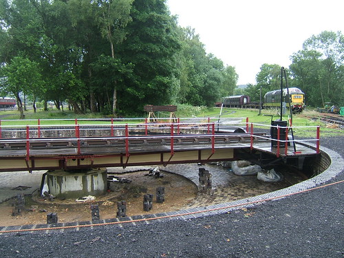 The 60-foot turntable at Rowsley during installation. This Cowans Sheldon Co. Ltd turntable (O/N 6181 5-Mar-1937) was originally supplied to Mold Junction M.P.D.
There's a little more information on the Peak Rail website here.
The re-commissioned turntable at Peak Rail was inaugurated by Pete Waterman on 1st May 2010, as described here.
 With Pete Waterman at the regulator, 8624 slowly reverses off the turntable (Photo: Sheila Rayson).
There is a collection of my pictures showing the Rowsley turntable in detail here.
Wolsztyn, Poland
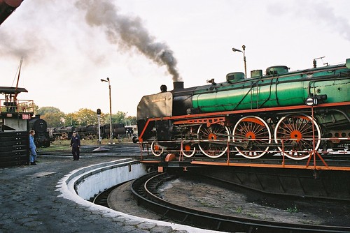 'Piekna Helena' on the turntable at Wolsztyn.
There's a brief description of my visit here and my pictures are here.
Kolomia, Ukraine
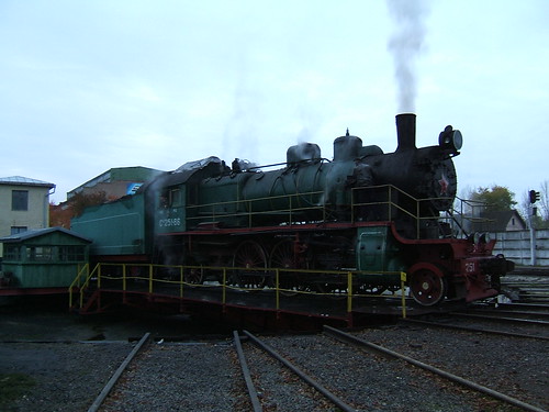 Su 251-86 on the turntable at Kolomiya.
There's an introduction to my trip to Ukraine, with links to other posts and pictures here.
Kiev, Ukraine
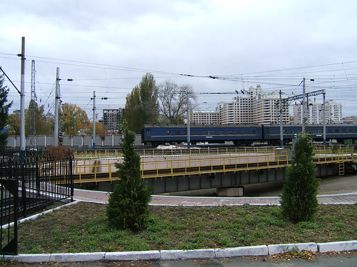 A large turntable in Kiev serving an 8-stall roundhouse and the works. Note the overhead catenary.
There's an introduction to my trip to Ukraine, with links to other posts and pictures here.
Mahlwagon, Yangon, Myanmar
 Mahlwagon Diesel Shed Turntable: 120 ton capacity metre gauge Mundt turntable built by Ransomes and Rapier in 1946.
There's a description of my visit to Mahlwagon Diesel Locomotive Shed here and my pictures showing the turntable at Mahlwagon are here.
A Model Turntable
 A model turntable in 4mm/foot scale.
There are more details of this model railway here.
There's an article on Wikipedia about railway turntables here.
[Link to 'The Oscillating Cylinder Engine' added 25-Oct-2015]


