skip to main |
skip to sidebar
The attractive former Caledonian Railway preserved 0-4-4 tank engine running number 419 provided steam traction for the main 2022 season at the Battlefield Line. My only driving 'turn' on this interesting locomotive was on 18th June 2022 June when I was on a shared turn with Adrian L. Sadly, this was interrupted during the Footplate Experience Course which preceded the public services by the development of a serious steam leak on the locomotive. This resulted in my spending most of the day 'baby-sitting' the failed locomotive whilst a Class 33 diesel operated the passenger trains.

Preserved Caledonian Railway '439' Class No. 419 leaving Shackerstone with the Footplate Experience service. Note the pronounced steam leak at the front end.
Following a previous problem, a gasket in the main steam pipe had been replaced and this was initially suspected as the cause of the new problem. However, when the locomotive had cooled sufficiently to determine the source of the leak, we found that the front left cylinder cover was the culprit. Nothing further could be done then, so I completed the day as 'second-man' on the Class 33 performing the last passenger round trip of the day. I subsequently learnt that, once cold, the cylinder cover had been successfully tightened up and the locomotive restored to traffic. Apparently, this locomotive has a history of this problem reccurring periodically.
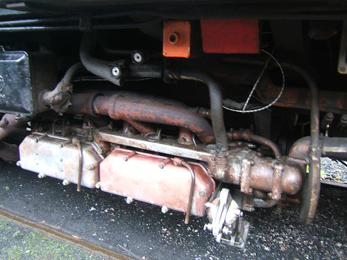
Limited access to the cylinders and valve chest front covers is via the hinged 'piano front' underneath the smokebox door. Accommodating two 18 inch diameter inside cylinders resulted in some of the front cover fixing studs being shared between the valve chest front cover and the adjacent cylinder front cover, as shown in the picture below.

Preserved Caledonian Railway 439 Class No. 419: View showing cylinder front covers, divided by the front cover for the vertical valve chest.
Design evolution of the 0-4-4T on the Caledonian Railway
Preserved locomotive 419 is the sole survivor of the Caledonian Class '439' 0-4-4T, introduced by McIntosh in 1900 and the standard suburban and branch line locomotive throughout the Caledonian Railway. But its origins go back to Dugald Drummond who had learned the importance of simple, rugged design through his experiences keeping locomotives running on the harsh routes within Scotland. For general use, a four-coupled tank engine with a bogie at the back appealed to him and, in 1884, Drummond had introduced the '171' class of 0-4-4T. Following rebuild, the last of these survived until 1944. Dugald Drummond's influence on subsequent Scottish locomotive design should not be underestimated. His successor, Lambie, saw fit to continue the design with some changes as the '19' class of condensing 0-4-4T and, in turn, when McIntosh took over in 1895, production of 0-4-4T carried on, first with the '92' class condensing 0-4-4T and then, in 1900, with the '439' class (very similar to the '92' class with boiler pressure raised by 10 p.s.i. and slightly better water capacity). Each of these classes used 5 foot 9 inch diamter coupled wheels but McIntosh also produced 12 locomotives with 5 foot 6 inch diameter coupled wheels giving better performance on the more demanding Cathcart Circle (Glasgow) and Balerno branch (Edinburgh) lines. So successful was the '439' class that production (with minor changes) continued from 1915 under Pickersgill with the final batch of ten emerging in 1925, with the majority of the class remaining in service until the 1960s.

Preserved Caledonian Railway '439' Class No. 419: Overall view during preparation outside Shackerstone Shed.
Braking
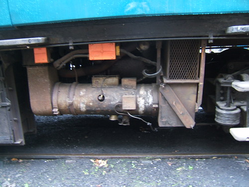
The Caledonian Railway was one of a number of UK railways which opted to fit the Westinghouse Air Brake System as the 'automatic brake', rather than the vacuum brake system used by many UK railways. Locomotive 419 retains its working steam-operated reciprocating air pump (mounted outside the cab on the fireman's (right) side. The pump charges an air receiver fixed below the bunker of the fireman's side. Via the Driver's Brake Application Valve in the cab, brake blocks on the coupled wheels are applied or released by air applied to the air brake cylinder. Flexible air brake hoses at each end of the locomotive allow the locomotive to be connected to an air brake system on suitably-equipped vehicles. After the Railway Grouping, the LMS additionally fitted a vacuum ejector, brake application valve and standard vacuum brake hoses to enable vacuum-braked trains to be controlled but the power brake on the locomotive remained air-operated. There is also a conventional handbrake, operated by a screw at the rear of the cab.

Preserved Caledonian Railway 439 Class No. 419: Westinghouse Air Pump immediately outside cab on fireman's side.

Preserved Caledonian Railway 439 Class No. 419: Driver's air brake application valve fixed to cab sheeting, left side.

Preserved Caledonian Railway 439 Class No. 419: Davies & Metcalfe Vacuum Ejector and Brake Valve in front left corner of cab. Just to the right, the vertical black tube with a white top is the mechanical control for the blower valve in the smokebox.
Locomotive Regulator
'Double-beat' or 'balanced' locomotive regulators are employed to reduce the effort required to open and close a steam valve against high pressure steam. The Wikipedia article here explains the principle, invented by John Hornblower around 1800. The arrangement was subsequently adapted for use as a locomotive regulator valve. There are a couple of posts in this blog about locomotive regulators - Part 1 talks about early type of regulators and Part 2 shows a modern type of locomotive 'double-beat' regulator. Whereas unbalanced regulators usually have one (or sometimes two) long handles so that the driver can produce sufficient leverage to adjust the valve, this shouldn't be needed with a 'balanced' design. Locomotive 419 is fitted with a 'balanced' regulator, controlled by a short, dual, red-painted handle.

Preserved Caledonian Railway '439' Class No. 419: View of boiler backhead showing red-painted regulator handle and other driving controls from fireman's side.
Cab layout
Because of the dual vacuum/air braking, there's a satisfying array of Bourdon gauges on the front spectacle plate inside the cab. The whistle is operated by a round plunger extending through the front spectacle plate, which produces the satisfying sound of a "Caley Hooter". The deep-toned, dignified sound of the "Caley Hooter"is my favourite whistle. When Stanier moved from Swindon to the LMS, he was asked to agree the whistle to be used on his new designs. A series of whistles were set up on a 'whistle bar' for demonstration and he chose the "Caley Hooter" so, brought up in LMS/GWR West Midlands, I became accustomed to the slightly mournful sound of Stanier engines. Many of my friends prefer 'chime whistles' but I always thought them rather 'foreign' (since I was not exposed to Gresley 'Pacifics' until later!).
More features of the cab layout can be gleaned from the collection of pictures here.

Preserved Caledonian Railway '439' Class No. 419: Gauges mounted on spectacle plate, L-R Train Pipe Vacuum, Boiler P{ressure, Duplex Air Brake, Carriage Warming. The round, polished steel plunger below is the whistle valve.
John Farquharson McIntosh
McIntosh was responsible for many Caledonian Railway designs. He was apprenticed at Arbroath in 1860 and, completing his apprenticeship in 1867, was appointed to Montrose Works where he spent 10 years. Returning to work following the loss of his right hand in an accident, he became Inspector of Lines from Greenhill to Aberdeen. In 1882 he became District Locomotive Superintendent at Aberdeen, taking a similar role at Carstairs in 1884. Next, he took charge of Polmadie running shed in 1886, next becoming Chief Inspector of the Caledonian Railway Locomotive Department at St. Rollox works in 1891 under Lambie. On Lambie's death in 1895, McIntosh became Locomotive, Carriage and Wagon Superintendent of the Caledonian Railway until 1914.

John Farquharson McIntosh
Locomotive, Carriage and Wagon
Superintendent Caledonian Railway
1895 - 1914
Book References
[1] ‘The McIntosh Locomotives of the Caledonian Railway 1895-1914’ by A. B. Macleod (Ian Allan 1948).
[2] 'An Illustrated History of L.M.S. Locomotives: Volume Three Absorbed Pre-Group Classes, Northern Division’ by Bob Essery and David Jenkinson (Oxford Publishing Co 1986) ISBN 0 86093 383 0.
Related articles on other websites
At the time of publication of this post, the following links were valid but, regrettably, with the passage of time, they may become 'broken'.
John F. McIntosh (Wikipedia)
John Farquharson McIntosh (Steamindex)
SRPS Collection Pages: 439 Class 419
No. 419 (55189)
Caledonian Railway 439 Class (Wikipedia)
There's a YouTube video of No. 419 at the Battlefield Line by Damien le Maistre Video here.
My pictures
Depending on the display device, the right hand edge of pictures included in this blog post may not display. To see an uncropped image, click on the picture. Alternately, you can find the image by following the link below which allows display or download in various resolutions.
Preserved Caledonian Railway 439 Class No. 419
At the end of 2021 the Battlefield Line secured 'Foxcote Manor' at short notice to work the Christmas season trains. My first turn on 'Foxcote Manor' was on 19th December 2021, as described in the post Battlefield Line 'Santa' Trains 2021 (which includes a brief introduction to the 'Manor' class).
Once the programme of 'Santa Specials' was complete there was a short break then a series of 'Mince Pie Specials' was operated, extending to the 3rd January 2022. I was rostered to drive on New Year's Day, with Stephen W. as fireman. I correctly anticipated that we'd still be running with a six coach train, limiting our opportunities for taking water, as explained in my post about my 19th December 2021 turn here. On New Year's Day, we were able to ensure that the tender was full before we moved out of the shed, as evidenced by water overflowing from various locations including the tender water gauge before the hose supply was turned off. Stephen had already set the fire and he was happy to share the oiling-round with me so we spent some time completing the examination and applying oil as required in companiable silence. By the time we'd completed this task, there was sufficient steam to move the locomotive just outside the shed in time to carry out some cleaning.
Until Nationalisation of railways in 1948, Great Britain's lines had been dominated by the 'Big Four' (LMS, GWR, LNER, SR), each with their own system for locomotive running numbers. British Railways integrated these numbers into a single series, generally by adding a 'fifth digit' representing the former owning railway in front of the old number. The Great Western had always used brass nameplates on the cab sides for the locomotive number so, in view of the cost of replacing these, former Great Western locomotives retained their original number. The other railways had normally used numbers painted on the cab sides, so they had to apply a prefix, ultimately a number but, for a time, the LMS used the prefix 'M' before the original number.

'Foxcote Manor' outside the shed at Shackerstone in British Railway's 'Mixed Traffic' livery of black (currently unlined) on New Year's Day 2022 (Battlefield Line)
In addition to the cabside numbers, most locomotives also carried the number at the front. The Great Western had always painted this, using yellow 'shaded' characters, on the front buffer beam, generally with a letter code indicating the 'home shed'. These painted identifications were removed and a cast iron numberplate was mounted on the smokebox door, in line with the other railways.
Motive Power Depots were also renumbered in a British Railways series which was an extension of the former LMS scheme (see Wikipedia article here) and a cast 'shedplate' was added. '84G', carried by 'Foxcote Manor', was Shrewsbury which provided motive power for the major passenger traffic on the Cambrian line.

'Foxcote Manor' outside the shed at Shackerstone showing smokebox door with cast number and cast shedplate
When the signalman opened the box, we shunted across to the train, nice and early, 'hooked-on' and started steam heating the stock. There was a little drizzle and we discussed rigging the 'storm sheet' between engine and tender but agreed not to do this unless the weather deteriorated. In fact, the drizzle stopped, the weather improved and it became a pleasant day although not very warm.
I'd assumed that the 1st of January would be a quiet day with people recovering from a late night on New Year's Eve but, in fact, there were already plenty of visitors around by the time we came off shed and it was very pleasant to be carrying good passenger numbers throughout the day. The 'normal' 4-round trip service was being operated, with departures from Shackerstone at 11:00, 12:30, 14:00 and 15:30. The usual timings applied, allowing a line speed of 25 m.p.h. except where lower limits were mandated.
We set off on our first run a little late, waiting for passengers to board, collected the single line staff at the signal box and proceeded up the bank to Barton Lane Bridge at the prescribed 10 mph. Beyond the bridge, we could gently accelerate to Line Speed. Tender first, the 3,500 gallon tender we were propelling allowed a much better view of the line than with the larger 4,000 gallon tender of a 'Hall' but it was also noticeable how exposed to wind the crew are travelling in this direction.
Market Bosworth station had re-opened to passengers and it was gratifying to see people alighting and boarding there. Shenton also had plenty of people around but Stephen and I were kept busy running round our train ready for our return journey.
On receipt of the 'right away' from the Guard, we made a gentle departure, complying with the 5 mph speed restriction because of the embankment 'slip' until clear of Ambion Lane bridge. Speed was then allowed to rise up Shenton Bank using full first valve on the regulator and adjusting the cut-off for best economy. The picture below shows the fireman's view looking ahead on Shenton Bank, with the Belpaire firebox cladding sheets pierced by four sunken washout plugs in a horizontal line with the domed cover of a fifth washout plug visible on the top front corner.

Fireman's view ahead on Shenton Bank (Photo: D. Mould)
We made our scheduled stop at Market Bosworth then continued to Shackerstone, where our arrival on platform 2 was watched (and photographed) by vistors on both platforms and the footpath leading to the engine shed.

'Foxcote Manor' arriving in platform 2 at Shackerstone on a Mince Pie Special (Photo: D. Mould)
With six coaches, we had to stop with the engine fouling the foot crossing to platform 1 so we quickly uncoupled and moved forward, allowing passengers to use the crossing. Once the passengers had finished crossing, we moved tender-first over the crossing into platform 1 where we stopped, to allow visitors the chance to photograph the engine.

'Foxcote Manor' poses for visitors outside the Victorian Tea Room at Shackerstone.
The cabside view below of 'Foxcote Manor' shows the 'Collett Cab' which was deeper (front to back) than Churchward's design. Both designs have a recess in the rear of the cab sheet, allowing the crew to lean out for better visibility but Collett's deeper cab had space for a brass-framed side window. The rearward extension of the cab roof is helpful, too (although less so when running tender first). The cab is narrow enough to accomodate a rather precarious footway outside, allowing enginemen to access the main foot-framing directly from the cab, assisted by an 'L'-shaped handrail provided near the side window. The cab side carries the painted route code circle in blue with the letter 'D' inscribed representing power classification (equivalent to British Rail 5 Mixed Traffic). The iconic GWR cast brass numberplate '7822' is mounted lower down the cab side.

Cabside view of 'Foxcote Manor' on Mince Pie Specials (Photo: D. Mould)
After the pause for photographs, we completed the run round, ready for the second round trip. The day continued very agreeably with our second, third and final round trips. Our engine steamed well and gave us no concerns, although it was clear that she'd put in significant mileage since the last heavy repair. Steve, in particular, had a tiring day with the firing and hooking on and off at each end of the line but we were both quite tired by the time disposal was complete.
A few days after my 'Mince Pie Special' driving turn, issue 289 of the magazine 'Heritage Railway' appeared with a picture of 'Foxcote Manor' at Shackerstone on the cover. Inside, a 6-page colour spread in their series 'PRESERVED LINE PROFILE' provided a good introduction to the Battlefield Line.

Heritage Railway Cover (Issue 289 Jan 21-Feb 18, 2022)
'Manor' Musings
This was my second turn on 'Foxcote Manor' during her short visit before returning to normal duties on the West Somerset Railway. Although sister engine 'Dinmore Manor' had previously visited the Battlefield Line, I hadn't had a driving opportunity so my previous experience of 'Manors' was many years earlier, limited to a delightful running-in and demonstration turn with 'Dinmore Manor' when the locomotive emerged from Tyseley Locomotive Works, plus a firing turn on 'Bradley Manor' at the West Somerset Railway. 'Foxcote Manor' had been hired-in at short notice to replace 'Wightwick Hall' which had been used during the 2021 season, so it was natural to compare 'Foxcote Manor' with 'Wightwick Hall'. After all, they're both Great Western 4-6-0 designs with two outside cylinders and, although both classes are credited to Collett, they remain firmly of Churchward lineage. There are technical differences between the classes, best understood by considering the third, intermediate design stage - the 'Grange' class.
Hall and Modified Hall class
The 'Hall' class is effectively a 'Saint' with smaller coupled wheels (six feet diameter rather than the 6 feet 8 and a half inch diameter of the 'Saint') but with the same boiler and cylinders (18-1/2 inch diameter with a 30 inch stroke).

Click for larger view
'Modified Hall' Class from British Locomotive Types 1946 (Railway Publishing Co. Ltd.)
No 'Saint' locomotive was preserved but there is now a reconstructed 'Saint' produced by converting a donor 'Hall' into 'Lady of Legend' by Didcot Railway Centre as described here.

Click for larger view
'Saint' Class from British Locomotive Types 1946 (Railway Publishing Co. Ltd.)
Grange class
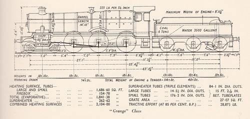
Back in 1911, Churchward had introduced the '43XX' class of mixed traffic 'Moguls'. They were well-liked, very successful and with good route availability resulting in over 300 being built. By the mid-1930s, earlier '43XX' were in need of replacement and increasing loads suggested an increase in power was also desirable. Collett decided on a 4-6-0, rather than a 2-6-0, wheel arrangement which became the 'Grange' class, keeping the accountants happy by re-using the 5'8" diameter coupled wheels and motion from withdrawn '43XX'. The 'Grange' is based on a 'Hall' with smaller coupled wheels (5 feet 8 inch diameter rather than the 6 feet of the 'Hall') but with the same boiler and cylinders (18-1/2 inch diameter with a 30 inch stroke). No 'Grange' locomotive was preserved but there is a project nearing completion to reconstruct a 'Grange' (see the website here). The 'Grange' class was very popular with footplate crews. It's often called "the enginemen's engine". It had a particular reputation for being free-steaming (perhaps oddly, as it used the same boiler as the 'Hall) and for pulling-power (whilst it had the same-sized cylinders as the 'Hall', there were some differences in the steam passages and, of course, the smaller coupled wheels gave a tractive effort advantage over the 'Hall'). Although I remember seeing 'Granges' in traffic during my childhood, I'm afraid the technical niceties were rather lost on me then.
Click for larger view
'Grange' Class from British Locomotive Types 1946 (Railway Publishing Co. Ltd.)
Manor class
However, the increased weight of the 'Grange' compared with the '43XX' restricted the new class (like Collett's 'Halls') to 'Red Routes'. So Collett also designed a smaller 4-6-0 design which became the 'Manor' using a new 'lightweight' boiler (Swindon No. 14), the lower axle loading allowing use on 'Blue Routes' in the West Country and Wales. The 'Manor' had slightly smaller cylinders (18 inch diameter rather than the 18-1/2 inch diameter of the 'Grange', but with the same 30 inch stroke) together with other changes.

'Manor' Class from British Locomotive Types 1946 (Railway Publishing Co. Ltd.)
Click for larger view
Related posts on other websites
Foxcote Manor Society.
7800 'Manor' class introduction (The Great Western Archive).
GWR 7800 Class (Wikipedia).
'Betton Grange' 6880.
'Lady of Legend' 2999.
Related posts on this website
Battlefield Line 'Santa' Trains 2021.
All my Battlefield Line posts.
My photograph albums
Where necessary, clicking on an image above will display an 'uncropped' view or, alternately, pictures may be selected, viewed or downloaded, in various sizes, from the albums listed:-
'Foxcote Manor' at the Battlefield Line.
All my Battlefield Line pictures.
At the end of 2021 the Battlefield Line was able to operate a very successful service of 'Santa' trains despite government restrictions caused by the Covid-19 Pandemic. Having taken pre-bookings to fill all the advertised trains to capacity, the management was faced with a major setback at the end of October when 'Wightwick Hall', which had been planned to work all 'Santa' trains, was 'stopped' due to leaking boiler stays. The locomotive owners decided to take the engine away for repairs. With no suitable replacement on site, the railway faced the major task of hiring an alternative locomotive at short notice, triumphing in securing 7822 'Foxcote Manor' to cover the vital Christmas Season.
Origins of the 'Manor' class
In 1911, Churchward introduced the '43XX' class of mixed traffic 'Moguls'. They were well-liked, very successful and with good route availability resulting in over 300 being built. By the mid-1930s, earlier '43XX' were in need of replacement and increasing loads suggested an increase in power was required. Collett decided on a 4-6-0 which became the 'Grange' class, keeping the accountants happy by re-using the 5'8" diameter coupled wheels and motion from withdrawn '43XX'. However, the increased weight of the 'Grange' compared with the '43XX' restricted the new class (like Collett's 'Halls') to 'Red Routes'. So Collett also designed a smaller, lighter 4-6-0 design which became the 'Manor'. By 1939, 80 'Granges' and 20 'Manors' had been produced. In 1950, a further 10 'Manors' (including 7822 'Foxcote Manor') were built by British Railways at Swindon and the someimes indifferent steaming of the class was cured by a series of fairly simple modifications based on the work of S. O. Ell.
'Manor' Class from British Locomotive Types 1946 (Railway Publishing Co. Ltd.)
Click for larger view
The 2-cylinder 'Standard' designs of the Great Western have Stephenson Link motion with four eccentrics mounted on the driving axle between the frames to provide the necessary valve events. With outside cylinders and valves, as used on the 'Manors', rocking shafts are required to transmit the movement of the dieblocks between the frames (via the intermediate valve rod, rocking shaft, valve link and valve rod) to the piston valves outside the frames.
This is illustrated in the well-known diagram below, taken from the 'Handbook for Railway Steam Locomotive Enginemen', published by the British Transport Commission in 1957. Second-hand copies of the 1957 edition and the Ian Allan reprint edition of 2014 (ISBN: 9780711037946) can still be found second-hand.
 Click on the above diagram to enlarge.
Layout of valve gear.
'Foxcote Manor' is currently in unlined black livery with the original 'Lion Astride a Mangle Wheel' totem on the tender. British Railways used lined black livery for mixed traffic locomotives and, in the twilight of steam, I was used to seeing Great Western engines in lined black, although I always imagined that Great Western mixed traffic tender locomotives must have felt embarrassed at being deprived of their 'locomotive green' colour carried before nationalisation. Liveries of locomotives and rolling stock is a fascinating area in itself and of particular interest to modellers. For a very quick introduction, try GWR Liveries on the GWR Modelling site.

British Railways totem on Collett 3,500 gallon tender in unlined black ('Foxcote Manor' at the Battlefield Line).
Events of Sunday 19th December 2019
I was rostered driver on Sunday, 19th December 2021 with Joe O. as fireman and Jeremy as trainee fireman. Years ago, I'd driven 'Dinmore Manor' after a restoration at Tyseley and fired 'Bradley Manor' on a service train on the West Somerset Railway but this was my first turn on a 'Manor' for some time (when 'Dinmore Manor' had previously visited the Battlefield Line, I'd managed a footplate trip but not had a driving turn). Joe and Jeremy had signed-on on time at 7.00 a.m. but fog on my road journey made me a few minutes late.

'Foxcote Manor' during preparation in the shed at Shackerstone on the Battlefield Line. Note the 'NOT TO BE MOVED' sign fixed to the front lamp bracket.
On arrival, I checked with Joe that he was taking water from the shed supply. At Shackerstone, the shed supply is a wall-mounted tap via a long flexible hose but it's a fairly low capacity feed. Normally, if there's space in the tender water tank, this supply will be left on all night but Joe told me this hadn't happened the previous night, so we'd be coming 'off-shed' with less than the 3,500 gallon tender water capacity. The water in the tender tank is indicated on a float-type gauge which rises up out of the tender in a short, vertical, cast column provided with a cast brass plate marked with readings in both gallons and water depth in feet. A small, brass indicator connected to the tank float moves up and down in a slot to show remaining water. This type of gauge isn't bad but it's always wise to allow some safety margin for lack of accuracy. The simple test of the gauge is to push the brass indicator down by hand and check that the float causes the indicator to 'bob' back to the original reading.

View of tender from the footplate, showing driver's side toolbox with the cast column of the tender water gauge in front ('Foxcote Manor' at the Battlefield Line)
Oddly, about the best water gauge I've used is the rather crude 'walking stick' arrangement favoured by Gresley on some of his engines. At the front of the tender, readily accessible to the footplate crew, a vertical pipe, connected to the tender tank, extends the full height of the tender water space. This pipe is perforated by a row of small holes, normally closed by a smaller, inner concentric pipe. A handle allows the outer tube to be rotated until the holes align with (I presume) another set of holes in the concentric smaller tube, allowing water to escape onto the footplate from all the holes below the level of water in the tender. An adjacent series of painted figures allows the indicated gallonage to be read off. I never quite developed the technique of avoiding catching some of the spraying water, often with wet boots, sometimes a wet arm as the handle was pushed closed after making a reading.
Normally, locomotives are able to replenish their water tank rapidly from a water tower adjacent to a railway line or, at more important sites, from a large storage tank serving a number of 'water cranes' or 'water columns' in strategic locations. In this country, the final stage of water delivery is normally via a short length of slightly-flexible pipe referred to as the 'bag', originally of riveted leather construction, which allows for a small misalignment between the locomotive tank filler and the delivery pipe
At Shackerstone, a large water tank is set at the top of the embankment near the south end of platform 2 feeding a water column with a swivelling arm just beyond the platform ramp. Unfortunately, this facility was not available to us because our train comprised six coaches, stabled with the northern end of the stock just clear of the barrow crossing from platform 1 to platform 2 used by staff and passengers to access platform 2. This meant the southernmost coach extended beyond the platform ramp, preventing access to the water column (unless the whole train was shunted). Shunting the train is not encouraged so, should taking water be required, the approved method is to water when returning to Shackerstone with a northbound train. This is done by stopping at the signalbox, uncoupling the locomotive and drawing forward to the column, taking water and then returning to pick up the waiting train and complete the journey to the platform.
The engine had been in use the previous day and was still quite warm so Joe soon had a decent fire established. He offered to oil the axleboxes and inside motion and I gratefully accepted. I'm finding it increasingly difficult to clamber around in the inspection pit and haul myself up to perch on a coupled axle during preparation. I contented myself with going underneath afterwards for a quick inspection.

Jan emerges from the pit after inspection 'underneath' ('Foxcote Manor' at the Battlefield Line)
Jeremy assisted Joe with the oiling, in order to familiarise himself with the layout and method, which is generally similar to the 'Hall' class, which I described in the post here.
I started my own oiling by draining the previous-day's condensate from the sight-feed lubricator mounted on the boiler backhead in front of the driver and re-filling with cylinder oil.

Sight feed lubricator ('Foxcote Manor' at the Battlefield Line)
Then, I applied motion oil to the various oiling points on the outside motion and tender, examining each part for obvious damage or defect in the process.

Jan applies motion oil to the left-hand connecting rod little-end on 'Foxcote Manor' at the Battlefield Line
Finally, I walked around the foot-framing completing motion oiling 'on top', including filling the vacuum pump oil pot with an oil/paraffin mix.

Jan poses on the front framing of 'Foxcote Manor' at the Battlefield Line, having completed the oiling 'on top'.
By the time we'd finished this oiling-round, the boiler was 'brewing' nicely so we moved outside the shed to empty the ashpan and finish preparation. As you leave the shed, the track is inclined downwards and, if the brake is at all reluctant to 'bite', vigorous help from the fireman screwing down the tender handbrake handle may be needed to bring the locomotive to a stand. On this occasion, I had to place the reverser in 'back gear' and cautiously open the regulator to produce sufficient retardation to stop.
Burning coal in a locomotive firebox leaves ash and incombustible material which should drop through the firegrate into the ashpan below. The ashpan is provided with one or more hinged doors which are adjusted by the fireman to regulate the primary (or 'bottom') air. Daily (or sometimes more often) this ash has to be removed by opening the damper door and scraping out the residue with an ashpan rake. This work can be heavy and is certainly dirty. The amount of ash and incombustible clinker-forming material depends upon the source, and hence the chemical analysis, of the coal.
To somewhat reduce the amount of sheer physical effort involved, two features were introduced in 'modern' designs - the rocking grate and the hopper ashpan. The rocking grate arranges the firebars on a series of axles which can be rotated from the footplate. A slight to-and-fro shaking action can be used 'in traffic' to help break up the formation of clinker and encourage it to drop into the ashpan. Rotation through 90 degrees opens up broader spaces to 'dump' the whole fire into the ashpan. The hopper ashpan allows the fireman to open the bottom of the ashpan so that gravity will empty the contents.
Locomotives in preservation were built in different periods and some have these 'modern' features, some do not. Often, these features have been added by restoration teams to assist in locomotive management. Oddly, whereas 6989 'Wightwick Hall' had a hopper ashpan but no rocking grate, 7822 'Foxcote Manor' has a rocking grate but ashpans are scraped-out with a rake.
The fireman and I reviewed the water situation. The tender water gauge indicated 2350 gallons (capacity is 3500 gallons). We agreed that, even allowing for the extra water which would be consumed train heating, we should have enough for the three scheduled trips plus a safety margin. If we changed our view, we retained the option, on approaching Shackerstone on the second or third trip, of uncoupling the locomotive and drawing forward to the column, taking water and then returning to pick up the waiting train.
Once preparation was complete, we moved 'Foxcote Manor' onto the 6-coach 'Santa Special' train in platform 2 so that we could commence steam heating of the stock well before passengers were allowed onto the train. We were advised to not exceed 18 to 20 pounds per square inch steam heating pressure, to prevent causing leaks in the rather 'tired' coach heating installation.
Our diagram called for three round trips to Shenton during the day, leaving Shackerstone at 12:15, 14:00 and 15:45, running tender-first to Shenton and chimney-leading back to Shackerstone.

Jan, Jeremy and Joe on the footplate of 7822 ('Foxcote Manor' at the Battlefield Line)
As departure time approached, I opened the ejector steam cock to create vacuum in the train pipe. Whereas 'Wightwick Hall' had the very effective multi-cone ejector mounted on the outside of the firebox (used on larger Great Western passenger engines and described/illustrated here), the 'Manors' retain the earlier ejector (see post here), so I was expecting a delay as air was exhausted from our six-coach train. The Train Pipe indicated the correct 25 in/Hg with the Reservoir managing 23 in/Hg. I closed the ejector steam cock to check for leaks and noted that the Train Pipe held up fairly well but the Reservoir (only affecting the engine and tender) started to fall. This seemed to be in line with a verbal report I'd had so I decided to review the actual braking performance in traffic with a view to making an entry on the Inspection/Defect sheet. I re-opened the ejector steam cock so that the guard could perform his own brake test.
Station staff were still shepherding late arriving passengers to their reserved seats as departure time passed but eventually all doors were closed and I acknowledged the 'Right Away' from Martin, the guard, with a hand signal and a whistle. The handbrake was released, both the fireman and I checked that the line was clear and our signal was still 'off' and, in a cloud of steam from the open cylinder drain cocks, we gently set off tender-first. The Collett 3,500 gallon tender is not very tall so the driver's view running tender-first is superior to that with a Collett 4,000 gallon tender (which 'Wightwick Hall' had been paired with). After a few yards, I wound the reverser away from the 'full gear' I'd started in and closed the drain cocks so that I could visually check that the whole train was following and that there were no signs of alarm on the train or the platform.
Jeremy collected the single line train staff from the signalman and I stressed the importance of both driver and fireman checking every time that it is the correct staff for the section being entered. The cutting leading to Barton Lane bridge is limited to ten miles an hour, pending relaying, but even when our whole train had passed clear of the restriction, I kept the train running at about 10 m.p.h. During this outward journey to Shenton, Father Christmas and his helpers would work their way through the train, talking to children (and their families) and issuing presents so a very leisurely progress is appropriate. A message from the train confirmed that our speed met with approval.
But it's much harder running a train at low speed. Rolling resistance alweays seems more noticeable and axleboxes don't have the same opportunity to 'warm through'. At low speed, the vacuum pump may not maintain vacuum without assistance from the vacuum ejector. Small changes in gradient or curvature of the line can produce noticeable changes of speed which, in theory, can be compensated by lengthening or shortening the cut-off without adjusting the regulator setting but, in practice, may require alternating periods of 'steam', 'no steam' and even 'brake'. So I was concentrating fairly hard all the way but, facing the tender, I did notice how much colder it was on the exposed sections of the line even with the Collett design of cab.
Collett's deeper, windowed cab is an improvement on Churchward's skimpier cab. But originally locomotives had no cab at all and, when roofless spectacle plates were first instroduced, they were resisted by many drivers. I certainly feel a driver must be fully aware of the surroundings, listening out for all the noises a locomotive can make. Gresley and Bulleid large-engine cabs are a little too enclosed for my taste and I think Stanier's designs for the L.M.S. best handled the necessary compromises in cab design.

Collett's windowed cab, showing the boiler backhead viewed from the tender. The small, rectangular, white object dangling from the fireman's spectacle is the battery/control box for the LED lights strung along the boiler handrails for Christmas ('Foxcote Manor' at the Battlefield Line)
Although passengers were not able to join or alight at Market Bosworth, we were booked to stop so that staff in the leading coach could quickly replenish the following coaches as required. Braking involves the driver admitting air through the brake application valve to partially destroy the vacuum created by the ejector or pump. There's a delay, depending on the train length, as the level of vacuum adjusts. In early braking systems, air was introduced only through the driver's valve but improved coach designs, as in our train, added a Direct Admission valve ('DA' valve) to each vacuum brake cylinder to sense the train pipe vacuum and, as the vacuum fell, allow extra air to enter locally to reduce the delay in brake application towards the rear of the train. Travelling at low speeds with an unfamiliar locomotive and an unusual consist of coaches, it was harder to stop correctly with the leading coach in the platform and the back coach overhanging the platform at the rear, particularly with the driver on the non-platform side. With the fireman relaying the position of the first coach along the platform, we stopped as required and I selected a suitable lineside 'marker' to use on future stops.
After a few minutes of staff activity on the platform, the guard gave the 'Right Away' and we set off again, resuming our progress at about ten miles an hour. Eventually, we approached Shenton, where braking was needed to comply with the 5 m.p.h. speed restriction over the embankment slip beyond Ambion Lane bridge. Although the station platform was on the driver's side this time, I'd been told that a marker post had been erected beyond the station to assist in identifying the correct stopping point, allowing us to stop accurately. Quite a crowd of passengers appeared alongside to admire the locomotive, safely behind the fence, and both Father Christmas and The Grinch joined them as there was the usual flurry of activity. 'Foxcote Manor' was uncoupled, the Single Line Staff was transferred to Martin so that he could operate the ground frame at the north end of the station and we ran-round our train.
We were told that we could return to Shackerstone at Line Speed, which was pleasant, particularly with a tender engine chimney-leading. Of course, the initial departure from Shenton was quite gentle, complying with the 'five mile an hour slack' to Ambion Lane bridge but, once the whole train had cleared the restriction, I was able to tug the regulator to 'full first valve' and let the speed build. I'm afraid I rarely manage to justify the use of 'second valve' considering the moderate gradients, moderate loads and moderate speeds which apply at the Battlefield Line.
When I was a driver at Birmingham Railway Museum, we had a saying "Your haven't lived until you've had a 'King' in second valve" and, with a tractive effort of over 40,000 pounds and a demonstration line only a quarter of a mile long that was certainly quite an experience. Perhaps the steepest line I've driven was on 'Kaitangata' at the mining railway at Shantytown Heritage Park in New Zealand where sanding was essential to prevent slipping. Heaviest train is probably 12 broad gauge coaches (500-odd tons) with a Class 'WP' in India (brief mention here) and fastest speed around 50 m.p.h. on Pacific 'Piekna Helena' in Poland (brief mention here).
We bowled along fairly merrily, slowing to 10 m.p.h. for the 'slack' through Market Bosworth station without stopping. As expected we were routed into platform 2 at Shackerstone and I'd been told that another marker post had been erected beyond the platform end to assist in stopping correctly. The locomotive was fouling the barrow crossing used by passengers so we uncoupled and dropped forward to wait in the north end whilst passengers crossed the line. It was quite misty but everyone seemed in good spirits.

Passengers streaming off the train and back to the car park after the first 'Santa Special' of the day ('Foxcote Manor' at the Battlefield Line)
Boiler pressure had held up well during the round trip to Shenton and water consumption, as shown on the tender gauge, was as expected, suggesting we'd have enough in the tank to complete our working so we finished the run-round and continued steam heating in preparation for our second departure. Joe had agreed to let Jeremy do most of the firing on the second trip. We set off and, as before, I was concentrating fairly hard on maintaining a gentle progress towards Market Bosworth but every time I checked the other side of the cab, matters seemed as expected and Jeremy's 'shovel action' appeared good. Once again, we stopped for a while at Market Bosworth then plodded on to Shenton where we ran round.

Shenton station with The Grinch and Father Christmas walking back to the platform after greeting passengers ('Foxcote Manor' at the Battlefield Line)
Once again, return was authorised at Line Speed. On the way back, I was pondering whether it would be prudent to stop and take water before we entered Shackerstone station. Shackerstone's Down Home 1 (an upper quadrant lattice post design) was off as we approached under Barton Lane bridge at the prescribed 10 m.p.h. and I realised, with horror that the brakes were dragging on. A quick glance at the boiler pressure gauge revealed the reason. Pressure was down to 160 p.s.i. and the vacuum ejector could not maintain sufficient vacuum in the train pipe. It was certain we'd come to a halt but I let the locomotive try for a few more yards before accepting our fate.

Shackerstone's Down Home 1 'off' for the 'Santa Special' ('Foxcote Manor' at the Battlefield Line)
Joe pulled one of the heavy fire-irons out and plunged it into the red-hot mass in the firebox. A bit of probing revealed quite serious clinker in the firebed. It's always problematic - failure to open the firebed up to sufficient combustion air means the boiler pressure will never recover but too enthusiastic 'action' destroys a carefully-crafted layered firebed, which will take longer to get hot again. Joe broke-up a fair amount of clinker then I took the 'bar' off him to satisfy myself that we had sufficient viable firebed to pull our train as far a the platform, Boiler pressure started to recover, encouraged by judicious use of the 'blower' (a steam jet exhausted through the chimney to enhance the draft on the fire when stationary which I often remind firemen can be the "last refuge of the desperate" and should be used in moderation). After about ten minutes, we'd regained pressure to release the brakes and, exchanging signals with the guard, we rather shame-facedly limped to the platform, uncoupled and stood down the north end, in full view of our delayed passengers who didn't seem unhappy at all.

Passengers assembling on platform 1 at Shackerstone with 7822 at the north end about to run-round ('Foxcote Manor' at the Battlefield Line)
We ran-round and coupled up to our train in the gathering gloom. Joe and I attempted to clean the fire and rebuild the firebed ready for our final trip. According to the tender water gauge, we'd ample water for the final trip so I was more worried as to whether our fire-cleaning would be adequate. Our third departure was late but we made our usual slow progress to Market Bosworth and then Shenton without incident but in the dark.
It's a different experience driving a steam train at night on a preserved line as there's little to see and hearing becomes more important in orienting yourself. There's a short article about the railway at night here. Depending on the weather, the sky may be a deep purple, with black silhouettes of trees and other lineside objects and pinpoints of electric light from houses and other features. But our last 'Santa Special' train moved through an impenetrable inky blackness with few visual clues except in the vicinity of each station where a row of electric lights threw yellow pools of light onto the platform surface and shafts or pinpoints of light from nearby houses appear. The business of running round becomes a lot harder in the dark and staff moving around on the ground need to be especially alert to the dangers of slips, trips and falls.
With running-round safely completed, Joe prepared the fire for the final run back to Shackerstone. To preserve some night vision, I averted my eyes from the glare when the firehole door was open. Joe had lit a gauge lamp and fitted it to the gauge lamp bracket provided so that the all-important water level in the gauge glass could be seen. We set off with around three quarters of a glass of water. The boiler pressure gauge wasn't very visible my side in the scattered light from the gauge lamp but the insistent hissing from the safety valves indicated that we were close to blowing-off. After clearing the Ambion Lane bridge speed restriction, the increased regulator opening silenced the safety valve hissing. We had been asked to make a special stop at Market Bosworth station to allow volunteers off, but as we waited for the 'right away', Joe reported "There's no water!". The tender water gauge still read '500 gallons' but neither injector seemed to be picking up any water. This was a serious situation.
Conventional locomotive fireboxes ('Stephensonian' fireboxes) have a double-skin water jacket construction with an inner firebox usually copper, which holds the burning mass of fuel, heavily stayed inside a larger outer firebox, usually steel, with water in between inner and outer firebox. Heat from the burning gases in the inner firebox passes readily through the copper and converts the water to steam. The level of water in the jacket must be above the highest point or 'roof' of the inner firebox at all times since the temperature of the hot burning gases in the firebox can exceed the melting point of copper (around 2,000 degrees Farenheit). As a warning, fireboxes now have a one or more Fusible Plugs screwed into the 'roof', with a hole through the plug sealed with an metal alloy solid at normal working temperatures. The alloy melts upon a dangerous rise in temperature, allowing water and steam to discharge through the hole in the plug onto the firebed. The noise and steam when this happens should alert an inattentive crew to the urgency of the situation. Allowing this to happen is called "dropping the plug" and is one of the worst sins footplate crew can commit. It's sometimes claimed that "dropping the plug" will extinguish the fire but it is intended only as a warning: indeed, there have been a few instances where the crew have not immediately realised that they had "dropped the plug". This is the 'Achilles Heel' of the steam locomotive - If you can't maintain a safe water level in the firebox, the only choice is to remove the source of heat without delay. Normally, this is done by "paddling out" the fire with the Clinker Shovel ('Paddle') and tossing the burning mass onto the ground one shovelful at a time. A locomotive with a rocking grate can 'dump' its fire more quickly (but a large mass of active fire dumped into the ashpan is not helpful). Quick action in withdrawing the fire may prevent or minimise damage to the locomotive.
We'd well over half a glass of water showing in the gauge glass so the question was, would that be sufficient to haul our train back to Shackerstone, uncouple and go for water before the level became critical? The fireman and trainee were both adamant that it couldn't be done. The fireman correctly pointed out that we would first be going uphill, which would tend to slightly increase the water level in the firebox and then be slightly downhill to Shackerstone, tending to reduce the water level in the firebox. My crew were sure we'd not be able to make it. But a locomotive footplate is not a democracy: I quietly confirmed that my assessment was that we could safely work the train back and we would depart as soon as we had the 'right away' from the guard.
Safety is always the primary consideration when working on a railway but before deciding to take the train on to Shackerstone, I'd already reviewed gradient and other issues. Gradients certainly affect the level of water in different parts of the boiler but the Battlefield Line has moderate inclines (Britsh Railways was able to use the line as a diversionary route for the West Coast main line during electrification) and, to optimise boiler proportions, the Great Western was an early adopter of the taper boiler used on larger engines (including 'Manors') which also tends to reduce the water level change on gradients. Withdrawing the fire at Market Bosworth then creates the problem of a disabled train which, in our case, was fully loaded with passengers three miles from where they wanted to be. Seeking assistance involves complying with a safety protocol to ensure that one incident does not create the conditions for another.
There's a simplified introduction to the working of single line railways here.
On the Battlefield Line, Section C of the Operating Rule Book covers Single Line Working, including the procedures for providing assistance to a disabled train. After agreement betweeen the crew of the failed train and the controlling signalman, protection (a red flag or lamp as appropriate) must be set a quarter of a mile from the failed train which must not attempt to move. A member of the footplate crew must take the train staff to the end of the single line section and travel back with the crew of the assisting locomotive to the disabled train. After coupling together, the assisting driver takes responsibility for train working and carries the staff.
The rules set out that, having put protection in place, a 'member of the footplate crew' (usually the fireman) must take the train staff to the signalman by any available means which could involve a lengthy walk in the dark. Assuming a suitable relief locomotive and crew is available, the assistant engine is allowed into the already-occupied single line section, carrying the person from the failed train with the staff (these are the conditions under which "two in a section" are permitted). I was keen to avoid the delay this would incur if possible.
Although hopefully a less-likely problem, I wasn't too sure of the endurance of the electric carriage lighting system. As railways developed, gas was commonly used for the lighting of passenger areas in trains, giving rise to a number of predictable fires following accidents. The worst, at Quintinshill in 1915, involved 5 trains and resulted in 200 deaths. Electric lighting using filamentary lamps, powered from batteries of secondary cells carried in a battery box attached to each coach underframe, remains in use on preserved railways now. The batteries are charged by a dynamo on each coach belt-driven from one axle. A simple regulator (similar to that formerly used on motor cars) connects the dynamo to the battery when the dynamo output is above a charging threshold, which occurs at around 15 m.p.h. This meant that during the 'Santa Special' operations, most of the time, even when moving, the batteries were not being charged. I wasn't sure whether special arrangements had been put in place to 'keep the lights on'.
So we set off from Market Bosworth into the darkness. Keen as I was to get towards our source of water, I wanted to eke-out that precious half a glass of water, so I settled on a very modest speed with a little less than full first valve on the regulator with the 'cut-off' linked up to about 50% to extract, by expansion up to the point of exhaust, as much effort as possible from each admission of live steam to the cylinders. I hoped that this would prove an economical setting. Every time I snatched a quick glance sideways at the gauge glass, I was relieved to see the level creeping down quite slowly but the fireman was paying close attention to the level, periodically using the 'flashlight' function on his mobile 'phone to better illuminate both gauge glass and pressure gauge.
Passing Shackerstone's fixed distant signal, I started to brake, admitting only small amounts of air into the brake pipe and then allowing the action of the vacuum pump to release the brakes, keen to avoid using steam in the vacuum ejector for as long as possible. Approaching Barton Lane Bridge at the regulation 10 m.p.h., the use of the ejector was needed to augment the pump. The Home 1 signal was 'off', so we were able to drift towards the box as I asked the fireman to prepare for dismounting as soon as we stopped and making sure the guard had applied his handbrake before uncoupling the engine so that we could ease forward for water. The Home 2 ground disc signal was also off, allowing me to go towards the box so that I could explain our intentions to the signalman. I stopped with the rear of our tender still on the plain line approaching the facing points - it's bad enough uncoupling in the dark without the added complication of stumbling over facing point equipment in the 'four foot'.
Once uncoupled, I moved towards the water column, asking the fireman to 'set' me in the correct position to ease inserting the 'bag' of the water column into the tender water filler. When taking water, there's nothing more dispiriting than getting a soaking because of poor alignment, particularly at night near the end of a long shift.
Whilst we were preparing the take water, Adrian L. bounded onto the footplate out of the darkness and checked the boiler water indication in the gauge glass, where a sliver of water was still showing.
"Oh, that's alright", he commented before discussing the next moves. I explained that I'd intended to take water, set back onto our train and complete the planned working. Adrian explained that he had arranged for the Class 33 to be started-up and brought to the south end of platform 1, where it rumbled alongside us as we started to take water.

Boiler backhead with boiler pressure gauge (upper left), carriage warming pressure (lower left) and BR-type 'coupled' gauge glass and protector ('Foxcote Manor' at the Battlefield Line)
I opened the water valve on the driver's side injector and, as soon as I confirmed that water had started to issue from the overflow pipe under the cab, I opened the steam cock. The injector immediately 'picked-up', producing the distinctive, reassuring sound of a working injector. The injectors produced by the Great Western are particularly reliable which is presumably why Riddles chose that pattern for use on his British Railways standard steam classes.
Adrian had considered using the Class 33 to pick up our train and take it into platform 1 whilst we sorted ourselves out, although the stock really needed to be in platform 2 for the following day. Confirming how much water we'd taken-on by looking through the tender filler to visually check the level in the tank, we agreed that it would be a little quicker overall for the Class 33 to pick up the train and bring it into platform 2 after I'd taken my light engine through platform 2 to stand clear at the north end.
Having hauled the train into the platform, the Class 33 uncoupled and came behind us so that passengers could use the barrow crossing and walk past the 'Manor' returning to their cars. The locomotive had not been fired for a while so the boiler pressure had started to fall but the fireman and I agreed that we should have enough steam to get 'on shed' and completely fill the boiler. Despite the delayed, unusual final approach to Shackerstone, our passengers seemed happy, thanking us and exchanging season's greetings.

7822 standing at the north end at Shackerstone after the final, eventful, round trip on 19th December 2021 ('Foxcote Manor' at the Battlefield Line)
Finally, the Class 33 moved through platform 1 to stand on the DMU siding, allowing us to follow to the ground frame giving access to the shed. Allowing for our reduced boiler pressure, a short run at the gradient approaching the shed got us inside and careful braking stopped us in the position we'd started from that morning, to ensure that the crew next day had access to the pit at the front of the engine. The engine was 'tied down', scotches set under a coupled wheel and the boiler was completely filled.
An interesting, if rather tiring, day.
Related posts on other websites
Foxcote Manor Society.
Related posts on this website
All my Battlefield Line posts.
My photograph albums
Where necessary, clicking on an image above will display an 'uncropped' view or, alternately, pictures may be selected, viewed or downloaded, in various sizes, from the albums listed:-
'Foxcote Manor' at the Battlefield Line.
All my Battlefield Line pictures.
I was booked to drive the 'Hall' at the Battlefield Line on Saturday, 30th October 2021 but a few days earlier, the locomotive had been 'stopped' due to leaking boiler stays. The railway put together a 'scratch' crew with a driver passed to drive the replacement diesel electric locomotive Class 20 110 but kindly invited me to have a training session on the diesel-electric if I wished.
I'm passed to drive on the diesel multiple units at the Battlefield Line but not passed on any of the various other diesel locomotives. About 30 years ago, when I was a regular volunteer at Birmingham Railway Museum, I was passed out by their Traction Inpector (whose 'day job' was Traction Inspector on British Rail) to drive their '08' shunter and visiting preserved Class 47 'Ixion' which was used for driving experience courses. I also did a bit of shunting with a visiting Class 31. I've always been a fan of the Class 08, a rugged and reliable machine, and my brief 'User Notes' (with a link to training notes prepared by British Rail, York) are here. Under supervision, I've since had 'hands-on' on a number of other diesel locomotives at various locations with mechanical or electric transmission (and shunting locomotives with hydraulic transmission) but never a Class 20, so I accepted the offer of a training session with Graeme as instructor driver.
Origins of the Class 20
Following Nationalisation of the railways in 1948, British Railways initially committed to building a range of 'Standard' designs of steam locomotives. By the time the last was built (Class '9F' 'Evening Star'), the 'Standard' stud numbered 999 locomotives. But difficulties in recruiting staff to operate and maintain these locomotives, combined with problems in the mining industry extracting the coal to fuel the fleet induced politicians to embrace a change of direction and replace steam with diesel and electric traction. This transition is briefly introduced in the post The Modernisation of British Railways. A series of 'Pilot Scheme' diesel locomotives were ordered from various manufacturers in four power ranges increasing from Type 1 (a general-purpose freight type) through Type 2 and 3 up to the express passenger Type 4.
English Electric were chosen for the Type 1 design. They had been building rugged diesel engines for marine and other applications for some time and their 'straight six cylinder' had given good service in the LMS diesel shunters. In 1947 they introduced a 'Vee' type of engine with pairs of cylinders set 45 degrees apart driving a common crankshaft. The 16-cylinder version (16SVT) of this engine had been used by Ivatt in the well-known LMS prototype main-line diesel electrics 10000 and 10001 and also in the Southern Railway's candidates emerging in the British Rail era as 10201, 10202 and, finally, the uprated 10203. This proven engine series was adopted for the 1000 h.p. (750 kW) Type 1 locomotive using their 8SVT Mark II diesel engine.
8 - number of cylinders
S - supercharged (actually turbocharged)
V - Vee form
T - adapted for railway use
Mark II (4-valve cylinder head)
The engine crankshaft was bolted directly to an English Electric 319-3C main generator with an output of 1070 Amps at 600 volts d.c. An English Electric 911-2B auxiliary generator 'overhung' on the main generator, producing 110 volts d.c. for the compressor, exhauster, traction motor blowers and battery charging.

Auxiliary generator, main generator, 8SVT diesel engine forming power unit of Class 20 locomotive.
The locomotive underframe was two longitudinal, parallel box sections (each formed from two channel sections plated-over top and bottom to produce a box section), with welded 'transoms' forming a rigid frame. Part of the two underframe box sections were sealed off to provide the modest fuel capacity of 390 gallons and two of the 'transoms' also served as balance pipes between the two tank sections.
The power unit was mounted on the underframe together with auxiliaries (including engine-driven fan, oil pump and water pump and electrically-driven air compressor, vacuum exhauster, traction motor blowers, fuel pump), all protected by a long 'bonnet' or hood , inset to give a 'running board' each side. A series of hinged access doors along each side allowed staff ready access to the equipment. At what was regarded as the rear of the locomotive, a driving cab was provided, with duplicated driving 'desks'
The assembled locomotive was mounted on two 4-wheel bogies using welded-frame equalising-beam design with helical springs and 3 foot 9 inch diameter wheels. Overall length was 46 feet 9.25 inches and weight 73 tons.
The four axles were each fitted with an English Electric 526/8D (/5D on first 50 off) nose-hung 6-pole series-wound, force-ventilated d.c. motor rated at 600 Amps, 300 volts d.c. driving through a single reduction gear.
The locomotives were arranged so that up to three units could be interconnected for multiple working from the leading cab using Electro-Pneumatic (E.P.) controls, allowing heavier trains to be worked.

Class 20 locomotive General Layout
Click for larger view
With the English Electric pedigree, the design proved reliable and did all that was asked of it so between 1957 and 1968 a total of 228 locomotives were built, originally numbered in the D8000 series but renumbered with the '20' prefix when the 'TOPS' system (see description on Wikipedia) was introduced in 1971.
The improved cab environment proved popular with some drivers and the good view of the line when running 'cab leading' was appreciated. The more restricted view ahead through the smaller window looking along the 'bonnet' when 'nose leading', although not that dissimilar from that on a steam locomotive, was not favoured and it became commonplace for the locomotives to 'hunt in pairs', coupled nose-to-nose, allowing drivers to adopt the preferred 'cab-leading' driving method in both directions.
The class gained an enthusiast following, who dubbed the class 'Choppers', leading to a number of units having been preserved. Perhaps more signicantly, examples still remain in commercial service in a number of countries. I think there are still occasional passenger railtours using the class 20. I wrote about one such tour I witnessed (but didn't travel on) in the 2015 post here.
Class 20 at the Battlefield Line
Graeme W. was booked driver with Jamie W. as Secondman. We were using the locomotive with final running number 20 110 which was stabled down the North End at Shackerstone, currently painted green and carrying its original number D8110.

Class 20 stabled at the North End at Shackerstone.
We all clambered over the locomotive as Graeme demonstrated the pre-start checks.

L: Air Compressor (with Traction Motor Blower behind) R: Vacuum Exhauster (Class 20 at the Battlefield Line)

View of 8SVT engine: Class 20 at the Battlefield Line

Main Generator (Class 20 at the Battlefield Line)
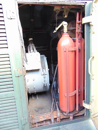
Overhung auxiliary generator and fire extinguishing installation (Class 20 at the Battlefield Line)
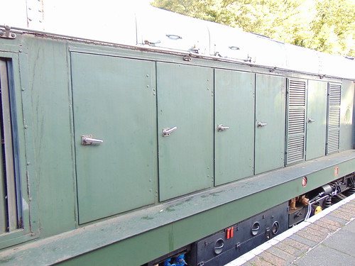
Left side of locomotive showing 'bonnet'. Note handrail above engine/equipment access doors and underframe-mounted battery box/battery isolating switch painted black (Class 20 at the Battlefield Line)
Graeme started the diesel engine. Electric start is provided by connecting the 110 volt battery to an extra winding on the main generator so spinning the engine crankshaft. We waited for the compressor to produce sufficient control air pressure and then Graeme shunted to our 6-coach train waiting in platform 2. Jamie 'hooked-on' ready for our first round trip to Shenton. Graeme drove the first trip then, for the rest of the day, I shared the driving with Graeme and (on trip 3) Adrian.

Class 20 110 arriving back at Shackerstone on 30-Oct-2021
The two driving desks are positioned for left-hand drive. Layout is standard with brake controls on the left, power and reverser controls on the right, with an inclined instrument panel facing the driver. Fairly crude swivel seats are provided fixed to the floor at each driving position.
Light engine movements are controlled by the 'straight' Air Brake but, when working vacuum-braked stock, control is via the separate Vacuum Brake Application Valve which is intended to apply the air brakes on the locomotive proportionally to the train vacuum but I need more training to properly get the 'feel' of this combination, tending to underbrake or, more often, overbrake and then having difficulty "blowing off" the vacuum to keep rolling.
The Driver's Surveillance Device (DSD) or 'deadmans' is in the form of an inclined, hinged metal plate on the floor which must be kept depressed when in motion or otherwise, after a short delay, all brakes are applied. The back wall of the cab has a handwheel for applying a 'parking brake', requiring numerous turns to apply or release the brake through a chain drive.
I did notice that, having left Shenton 'nose-leading' and mounted Shenton Bank, advancing the power controller to produce line speed in the cutting did produce a 'business-like' exhaust noise. At the end of the service schedule, I was able to leave the locomotive with Graeme as it was being used again for an evening special. All-in-all, a good day.

Class 20 at the Battlefield Line showing cab and Number 2 Bogie, with Jan in earnest conversation.
Related Posts on this site
The Modernisation of British Railways.
Class 08 User Manual.
Related Post on other sites
English Electric diesel engines.
Book references
[1] 'BR Class 20 Diesels' Michael Oakley (Bradford Barton) ISBN 0 85153 419 8.
[2] 'Description and Fault Finding Instructions for Drivers' (English Electric/BRB Book FS227)
[3] 'Diesel Traction Manual For Enginemen' (BRB 1962)
My pictures
Class 20 at the Battlefield Line
Depending on the display device, the right hand edge of pictures may not display. To see an uncropped image, click on the picture. Alternately, you can find the image by following the 'My pictures' link and display or download the image in various resolutions.
I was rostered as DMU (Diesel Multiple Unit) driver at the Battlefield Line on Saturday, 2nd October 2021.
The 'set' comprised the Driving Motor car at the north end coupled to the Single Unit ('Bubble Car') at the south end: the customary arrangement at present. There's a second Driving Motor Car which is currently receiving attention in Shackerstone M.P.D. before being reunited with its 'other half' to form a 2-car unit. The set normally has four 150 h.p. in use, one to each bogie but one engine on the Single Unit has been using excessive engine oil for a while and the Owner recently decided to isolate that engine and run with three engines until a replacement engine could be fitted.
The thoughtful design of the 'Modernisation Series' DMUs makes it easy for a driver to safely isolate an engine which has failed in traffic, allowing the unit to 'limp home' with reduced power and this had already been done. Firstly, the Final Drive had been isolated using the hook-ended, long-handled tool stowed in the guards compartment.

Guard's compartment in 55005: The long, thin rod with a handle at the top stowed vertically in between the red-painted Brake Setter and the Guard's seat is the 'Toasting Fork' to isolate the final drive.
The 'toasting fork' allows the driver to reach over the top of the bogie, grasp the isolating switch with the hooked end and twist the switch to the 'isolated' position.
The vertical bar is the Final Drive Isolating Switch in the 'engaged' position. When horizontal, the drive is 'isolated'.
Secondly, a carriage key had been used to electrically isolate the engine, using the isolating switch on the underframe near the engine.
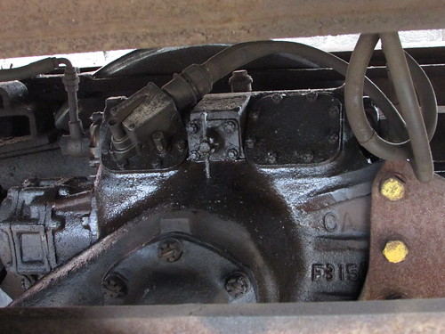
'Flat 6' DMU engine. The orange-painted square box mounted on the underframe above the engine is the switch (operated by a carriage key) to electrically isolate the engine.
It didn't take long to check oil and fuel levels, make sure auxiliary drive belts were intact and look for anything not quite right, then each engine was electrically started from the ground. Two out of three started: one refused to turn over and just made an 'Ug' sound. I started thinking about finding the battery charger and setting it up to get more life into the battery but decided to make one more attempt and this time the engine turned over sluggishly but enough to fire and we were away.
Stephen W. was booked Guard and he arrived nice and early. The day started dull and rather cold so we anticipated poor passenger numbers but when we moved the train from the DMU siding where preparation is carried out into the platform, there were quite a few passengers already waiting. We set off a few minutes late and, for a time, the weather deteriorated with intermittent heavy rain, requiring the use of the air-operated windscreen wiper. Market Bosworth had been closed to passengers during the limited operations as Covid restrictions were eased but we were scheduled to resume the intermediate stop. Whilst waiting for the Guard and Market Bosworth Station Staff to conclude station duties, I took a picture of the passenger compartment behind the driving cab.

Battlefield Line 2021: DMU on 2-Oct-2021 at Market Bosworth on the first northbound service.
We carried on to Shenton with improving weather. In fact, later in the day there was quite a pleasant sun. The dull start to the day made me anticipate poor passenger numbers but quite a few passengers turned up for each service which made the whole day very worthwhile. But I'm sure the passengers were relieved that the carriage heating was working! There are two underframe-mounted heater units on each coach. Diesel fuel (electrically ignited) is burned in a cylindrical combustion chamber and electric fans blow warmed air through ducts into the coach. The heaters are controlled from a simple panel in the Driver's cab and a switch allows fan-only operation in summer. Safety circuits are provided to ensure correct operation. The principle is similar to some warm-air portable heaters used in industry.
 One of the two underframe-mounted heater units on each coach.
Stopping at Market Bosworth on the return trip, we picked up a large family group celebrating the birthday of one of the group. They were all staying at the Bosworth Hall Hotel in Market Bosworth and they'd decided to have a round trip on the train. The jolly crowd left us at Market Bosworth on our second north bound journey.

Battlefield Line 2021: DMU on 2-Oct-2021 showing a birthday party alighting at Market Bosworth from the second northbound service.
Our Guard had recently been passed-out to drive the DMU but had not yet had a rostered driving turn so we agreed to 'swop roles' for the third round trip so that Stephen could drive whilst Jan carried out the guard's duties.

Battlefield Line 2021: DMU on 2-Oct-2021 showing Jan completing the Guard's Journal on the third round trip.
I was back in the cab for the final round trip to Shenton then the unit was stabled in the DMU siding, final inspection made and paperwork completed after an enjoyable shift.
Related posts in this blog
All my Battlefield Line posts.
All my DMU posts.
My pictures
Battlefield Line 2021.
All my Battlefield Line pictures.


