The following notes for shunters are aimed at persons working on preserved standard gauge railways in the United Kingdom. The Shunter (where I mean the person on the ground involved in marshalling a train and coupling and uncoupling vehicles - not the locomotive engaged in the marshalling), is engaged one of the more dangerous tasks carried out on a railway. This role may be carried out by dedicated shunters, by Guards or Footplate crew. Anybody carrying out this work must be suitably trained and assessed as competent and be using the specified Personal Protective Equipment (PPE).
The shunter must not go between two vehicles unless they are both stationary and there is a 'Clear Understanding' with the driver of any locomotive. Muttering "Going between" and disappearing between vehicles is not adequate - there must be an explicit acknowledgment from the driver that it is safe to go between vehicles.
Please remember "Jan's Three Rules" for working on a railway:-
1. Do it Safely.Just moving around in a railway yard presents a challenge. The ground is rarely level and can rapidly change texture (ballast, wood, earth, paving, tarmac). There are numerous obstructions to catch out the unwary. In addition to various posts, fences and misplaced debris, there may be hand levers to operate points. If there's a signal box or ground frame in the vicinity, in addition to various types of signal there is likely to be point rodding, cranks/compensators, signal wires and signal pulleys.
2. Do it Safely.
3. (Can you guess?) Do it Safely.
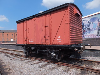
This introductory part deals with the two simplest types of coupling used on freight wagons mentioning the hand brakes typically provided. In the steam era, the 3-link and 'Instanter' couplings were the most common types used on freight trains. Individual vehicles usually had hand-operated brakes, used as both a 'parking' brake and, partially applied, as a means of retarding the vehicle when descending an incline. On the move, the locomotive brake and the handbrake applied by the guard in the Brake Van at the rear of the train were the only means of controlling the train. It became mandatory on trains carrying passengers to have an 'automatic' brake operable throughout the train. Gradually increasing numbers of freight trains were fitted with 'automatic' brakes on all or at least a group of vehicles next to the engine (called a 'fitted head'), allowing higher running speeds.
The 3-link Coupling
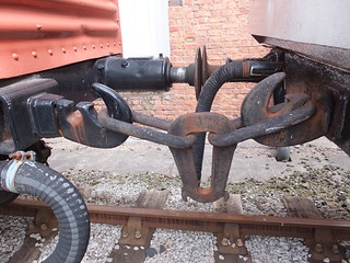
The simplest coupling in use on standard-gauge railway vehicles in the United Kingdom comprises a strong Drawhook from which are suspended three links. Whilst easy and quick to attach or detach this type of coupling to an adjacent vehicle, there will always be 'slack' between the vehicles, and the driver must be aware of this. Because both adjacent vehicles have the same design drawhook and similar coupling links, the shunter can normally choose whether to put the left coupling links on the right drawhook or the right coupling links on the left drawhook. Should a link fail on a journey, it was possible to complete that journey by using the 'good' coupling links. However, most freight guards would keep a 'spare' 3-link coupling to hand so that a failed coupling could be replaced. Particularly in freight yards, spare 3-link couplings were often to be found lying around.
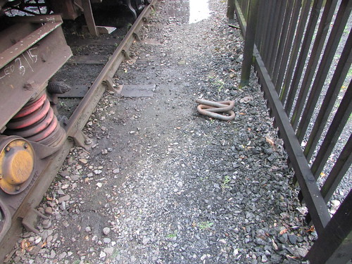
A spare 3-link coupling was often to be found lying around.
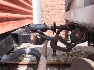
The hole in the drawhook which accepts the associated link is accessed via a 'keyway' narrower than the diameter of the steel bar from which the links are made. The prevents a coupling from becoming accidentally detached from its parent drawhook but, without special provision, this would prevent a failed coupling from being easily replaced. The 'special provision' is called the 'Kedge' - a flattening part way along a long side of the end link. This flattening makes the kedge thin enough to pass through the keyway in the drawhook, allowing the coupling to be suspended from the parent drawhook.

3-link coupling, showing the 'kedge' in the long side of the end link which allows the coupling to be suspended from the parent drawhook.
The slack in the couplings on this type of train (referred to as 'loose-coupled') can be used to advantage by a driver in starting a heavy train. If the locomotive has eased back on the train, only part of the train weight has to be moved initially with additional load taken by the locomotive as couplings tighten towards the rear of the train. However, on an undulating route, additional skill is needed as the wagons 'bunch up' on down grades and 'pull out' on rising grades. Co-operation with the Guard, in operating the handbrake in the Guard's Van, can minimise the effects.

3-link or 'Instanter' Coupling: End view (from a Railtrack document).
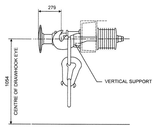
Instanter Coupling: Side view. The 3-link coupling is similar, but with a plain, oval centre link (from a Railtrack document).
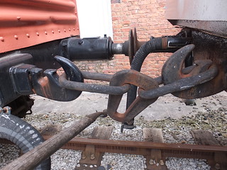
The 'Instanter' Coupling
The 'Instanter' is similar to the 3-link, except that the middle link has a complex shape with two 'ears' allowing it to be placed in either of two positions, corresponding to 'long' or 'short'. In the 'long' position, the coupling has the ease-of-use of the 3-link. In the 'short' position, some of the 'slack' is taken out of the coupling and the motion of the train may be better (particularly for the Guard at the end of the train!).

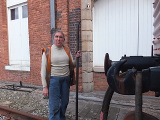
The Shunting Pole
The Shunting Pole was an invaluable aid to Shunters. A stout, round, wooden staff, usually made from ash was provided with a specially-shaped metal end, curled like the tail of a pig. Armed with this tool, a skilled operator could rapidly couple or uncouple both 3-link and 'Instanter' couplings. 'Instanter' couplings could also be turned from long to short or short to long positions. This was done with the shunter standing alongside the wagons so it was both safer and faster. Some strength and some practice is required to become proficient. It's also important to check the pole regularly for damage. In former times, employees were sometimes tempted to make use of shunting poles in unauthorised ways. The frequent need to apply or release wagon handbrakes could tempt the shunter to use the shunting pole as a lever (rather than the properly-designed brake stick) or, worse, to avoid chasing a wagon down a siding shunters might wedge the shunting pole into the underframe of a moving wagon and ride on the protruding pole. Serious injury or death could follow so no modern volunteer should copy these risky practices.


Wagon Brakes
Freight wagons are provided with hand-operated brakes, usually capable of being applied from either side using a long, pivoted brake lever but short levers or handwheels are also used. Even with a long brake lever, significant downward force may be needed to apply the brake effectively. The Brake Stick (described below) can assist in safely applying and releasing handbrakes. There's a little more about brakes on railway vehicles here and pictures of a range of preserved wagons in the album Freight Rolling Stock.
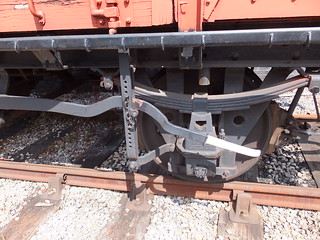

The Brake Stick is wooden, about 3 feet long. Half the length is rectangular, around 2.5 inches by 2 inches in section. The remainder is rounded and tapered to about 1.25 inches diameter at the end. The rectangular section is placed over the Brake Lever and wedged under the underframe or the spring. Pressing down on the rounded section provides additional leverage and the pin is inserted in a pair of holes to retain the brake force. The brake stick may be needed to safely remove the pin when it is necessary to release the brake. As with the Shunting Pole, it's important to check the Brake Stick regularly for damage.
More on this topic at The Role of the Shunter (2).
Related posts on this website
MIC - Brakes.
Related photograph albums
Pictures from may be selected, viewed or downloaded, in various sizes, from the album listed:-
Freight Rolling Stock.
