Friday 30 December 2011

Heaviest Single Load carried by British Railways

My introduction to Tipton Curve box here refers to the "largest single load ever carried by British Railways". On 27th March 1965, I signalled this load through Tipton Curve Junction, thanks to the kindness of my friend Tom. Earlier that day, Tom and I had covered Deepfields from 8.0 a.m. to 2.0 p.m. It looks as if we 'doubled back' to cover the evening working. I've located my Train Register covering these movements and a copy appears below.

I don't know whether larger loads have been carried since but at 122 feet long and weighing 240 tons, it was fairly impressive. In theory, any weight can be carried by rail, provided it is spread over sufficient carrying wheels so that the Civil Engineer's axle load limit is not exceeded. As far as size goes, the British loading gauge is quite restrictive (much more restrictive than, say, the 'Berne Gauge' widely adopted in continental Europe). Obviously, the load can't be so large that it starts bumping into bridges or other lineside structures. Length is significant, too, because as the load traverses curves, overhang and end throw may put structures or trains on adjoining lines "in harm's way". Considerable pre-planning is necessary before 'Out-of-Gauge' loads can be run.

As far as block signalling was concerned, three different 'Is Line Clear?' bell signals were generally authorised, depending upon just how out-of-gauge the load was. There was also a special bell code to ensure adjoining lines were 'blocked' where necessary. The bell signals are listed below:-

Bell Code Description
2-6-1 Is line clear for a train which can pass an out-of-gauge or exceptional load similarly signalled on the opposite of adjoining line?
2-6-2 Is line clear for a train which cannot be allowed to pass an out-of-gauge load of any description on the opposite or adjoining line?
2-6-3 Is line clear for a train which requires opposite line, or an adjoining line to be blocked between specific points?
1-2-6 Opposite line, or adjoining line used in the the same direction, to be blocked for passage of train conveying an out-of gauge load.

There was a special notice covering the working, but I don't have it. Because of the tight curve between Bloomfield Junction and Tipton Curve Junction, the train was to travel as a '2-6-3' between these points. It was then allowed to go forward to Princes End as a '2-6-2'. Two different reporting numbers were allocated - 8Z03 normally, changing to 8Z04 in between Bloomfield Junction and Tipton Curve Junction.

Tipton Curve, Saturday 27th March 1965

We opened the box at 7.15 p.m. and just after 8.0 p.m. we acknowledged the '1-2-6' to Bloomfield and 'Blocked Back' in the Tipton direction. We 'took on' the '2-6-3' at 8.17 p.m. and immediately 'Sent on' a '2-6-2' to Princes End. We received 'Section' from Bloomfield at 24 minutes past and the train passed, at walking pace, five minutes later. The special train was diesel-hauled and carried a long silver-coloured drum on a number of wagons. It passed me at walking pace and was accompanied by more-than-enough inspectors making sure it didn't get into trouble. As soon as I sent 'Train out of Section' to Bloomfield, he lost no time in closing the box. I also removed the 'Block Back' to Tipton. At 8.36, Princes End sent 'Train out of Section' and we closed Tipton Curve box.

DOWN

UP

I think there must have been a series of these shipments but I only saw one myself. Below is a cutting from the 'Express and Star' dated 31st May 1965 showing one of the massive drums leaving John Thompson by road for rail shipment from the goods depot at Ettingshall Road. Apparently, they were Steam Drums for the power station at Eggborough. An idea of just how different the world was then can be gained from the employment adverts adjacent to the picture of the Steam Drum, particularly noting the salary of two thousand pounds a year being offered to the Works Manager of a presswork company.

Sunday 25 December 2011

Sedgeley Junction - Signalling Alterations 1964

The Dudley - Birmingham (Snow Hill) passenger service finished on Saturday June 13th 1964. Three weeks later, I did a morning shift at Sedgeley Junction on Saturday 4th July 1964. This was the last day of the Dudley - Walsall and Dudley - Dudley Port services. The timings are on pages 38 and 39 of Jan's Train Register Book.

I think it was that day I found copies of the drawings detailing the changes to be carried out to the interlocking at Sedgeley Junction box which were intended to 'single' the line to Dudley Port, retaining it as an Engineer's Siding. I hastily made my own sketches from the drawings.

I never returned to Sedgeley Junction so I don't know whether the planned alterations were introduced - on 20th September 1964 the box was destroyed in a fire. Certainly, alterations were made at Dudley Port, turning the branch into an Engineer's Siding. The changes at Dudley Port are described in the section titled 'Changes at Dudley Port Friday 2nd October 1964' in the post Traffic Movements on the Stour Valley, 1964

On Sunday 20th July 1964, Sedgeley Junction signal box was destroyed by fire and not re-instated. In the immediate aftermath, all the signals at Sedgeley Junction were maintained 'off' and the adjacent box at Horsley Fields was manned continuously to shorten the block section.

The four sketches I made are reproduced below. Click on any sketch for a larger view. These sketches not only show the alterations but give a good idea of the the situation in the previous period when I worked the signal box. For more information about L & NWR signal boxes and the 5.5 inch centres Tumbler Interlocking Frame fitted at Sedgeley Junction, refer to the excellent book 'A Pictorial Record of L.N.W.R. Signalling' by Richard D. Foster, published by Oxford Publishing Company in 1982 (SBN: 86093 147 1).

1. Title Page

This is a simplified sketch of the standard title sheet in use at the time. Note that the 40-lever frame is made up from two 15-lever girders and one 10-lever girder.

2. Locking Diagram showing Alterations

The book referred to above has a copy of an interlocking diagram dated 1878 which uses virtually identical symbology to this sketch. I'm afraid my hastily-made sketch isn't too clear. The vertical lines represent the Hook Racks operated by each lever which move in the Guide Rack. Horizontally, there are twelve channels for U-section Locking Bars. The symbol ' ][ ' indicates that two shorter Locking Bars share the same channel. Horizontal movement of the Locking Bars is effected by a Drive Stud attached to the Locking Bar operated from an 'L' shaped bell crank called the Actuator from the movement of the appropriate Hook Rack. Full or Half Locks attached to each Locking Bar allow or prevent movement of the Hook Racks attached to other levers as required by the desired interlocks. The whole Locking Rack is held together by a series of vertical Backbones which hold the Locking Bars and Hook Racks in position.

3. Locking Table showing Alterations

For each lever, this table tabulates what lever must be pulled before the lever in question can be pulled. The last three columns show which other levers are locked Normal, locked both Normal and Reverse and released by the lever in question.

4. Lever Colours, Pulls, Nameplates showing Alterations

This table shows which positions are working levers, spare (unused levers) or spaces (position where a lever could be fitted). The last three columns show, for each lever, the colour, the detail on the Pull Plate and the text on the Name Plate.

Sedgeley Junction (again)

I introduced this fascinating signal box in the post Sedgeley Junction. I hadn't located my early notes so I produced a (not very good) box diagram from memory for this post. Because of interest from my friend Phil, I started to expand on this theme in the post Sedgeley Junction Remembered. Eventually, I located a notebook containing notes on traffic movements at Sedgeley Junction which got issued in a whole series of posts called 'Traffic Movements at Sedgeley Junction 1962-1963'. Later still, I found a train register book with detailed timings of some of my visits. I've described this in the post Jan's Train Register Book with a link to the complete document. If this all seems a little backwards, well, it is but after losing the information for half a century, it seems better to try to nail it down in a less-than-ideal manner now.

All this is leading up to saying that I've found more contemporary notes and sketches relating to Sedgeley Junction. Rather than wait another fifty years for these to be converted into a better form, I'll post them as they stand. Once you're familiar with the way a signal box is laid out, it becomes easier to understand any other signal box. In the earlier post Deepfields in Detail, I give an explanation of some of the features of an L&NWR box, and it may be worth referring to that post for more information.

Box Diagram & Block Shelf

The best way to orient yourself in any signal box is to study the box diagram. I've also sketched the layout of the block shelf:-

Sedgeley Junction - Copy of box diagram and sketch of block shelf layout. Click on sketch to enlarge.

At Sedgeley Junction, the block shelf only extended between levers 1 to 30 - the last ten lever positions had no block shelf above. The four L & NWR Block Instruments and the Block Switch (allowing the box to 'switch out') huddled together near the left end of the shelf. The order, from left to right, was Horsley Fields, Dudley Port Junction, Block Switch, Dudley East (Main Lines), Dudley East (Loop Line). To the right of the block instruments, the Box Diagram was suspended from the roof and to the right of the diagram there was the antique telephone and L & NWR Single Stroke Bell communicating with Conygree Siding Ground Frame.

The front face of the block shelf mounted a number of Signalling Repeaters. From left to right there was the Distant repeater for lever 1 (a miniature yellow arm on a brass 'signal post'), the Track Circuit Indicator for TC2205 (discussed below) and the Weight Bar Repeater for lever 7 (the Up Distant from Dudley Port High Level direction). The right hand end of the block shelf was fitted with an indicator for the track circuit. This was in the form of a pointer moving between 'LOCKED' and 'FREE'. To the left of this indicator was a Sealed Release. The front face of the block shelf was also furnished with a number of protruding nails to suspend a number of reminder links used as Lever Collars and 'Train Waiting at Signal' reminders for the commutator of block instruments. As far as I remember, lever 35 (the Down Slot protecting Conygree Siding) and lever 39 (the Down Distant) also had repeaters. In the absence of a block shelf above these levers, each repeater was mounted on top of a vertical tube rising out of the floor behind the frame.

Looking at the box diagram, note that, with the point levers 'normal', both Up and Down roads are set towards Dudley Port High Level (not as shown in my earlier posts). Presumably, this is considered 'safer' as any vehicles running away would be diverted onto a rising, rather than falling, gradient. However, when I was visiting levers 20 and 21 were left reverse for most of the time because that was the way most trains went.

Facing points 18 and 21 were each provided with a mechanical locking bar (to prevent attempted movement of the points when vehicles were passing over). Facing point 30 had been modernised and protection was provided with a track circuit (T1). This track circuit controlled a Back Lock on lever 29 and the associated Locked/Free indicator mentioned above.

Track circuit TC2205 was something of an oddity. I believe it indicated the presence of a train in Dudley Port Low Level station on the Down Line. Since this was in Horsley Fields block section, it wouldn't normally be of interest to Sedgeley Junction. It might have been involved in the control of the electric lock on the Down Walsall Home (lever 38 - the only signal in the box with an electric lock) but I don't know. I can't remember our taking a lot of notice of this track circuit although you'd hear a 'click' as a down train left the track circuit and the indicator moved back to 'TRACK CLEAR'. Originally, the L.M.S. numbered all its track circuits in a single series, hence the rather large number 'TC2205'. But as track circuits started to proliferate, a change was made so that the track circuits for each box were in a 'local' series, starting with T1, without renumbering any existing track circuits.

Levers and Pulls

Then, you need to study the layout of the levers. The colour indicates the function, of course, for instance red for stop signals, black for points and so on. Fixed to the front of each lever is the 'Pull Plate' showing which other levers need to be reversed before that lever can be pulled. Further guidance was given by the text on the Back Plates fixed on a board behind the levers.

Sedgeley Junction - Lever Pulls (First column is lever number, next columns list the 'Pulls', final column gives description as on the Back Plates) Click on sketch to enlarge.

This is fairly straightforward, although I suggest that the pull 'Lever 24 requires Lever 36' is a transcription error for 'Lever 24 requires Lever 35'.

Gradient profiles

It's important that the signalman has a clear idea of prevailing gradients. If a train becomes divided, particularly a 'loose coupled' freight without continuous brakes, it's important that the signalman understands what may happen to any vehicles running away. Gradient profile information is included on the box diagram and is given below.

Sedgeley Junction - Gradient Profiles. Click on sketch to enlarge.

It was a tough slog for freight trains from Great Bridge up to Dudley. The diagram above shows a section of 1 in 62 just outside Sedgeley Junction box. That, combined with weight transfer on the wheelsets of locomotives passing through common crossings on poinwork near the box resulted in many engines 'losing their feet' near the box. In contrast, the line from Sedgeley Junction to Dudley Port High Level was, according to the diagram, a bit of a switchback.

Saturday 24 December 2011

Sealed Release for Signal Boxes

Most people are familiar with a 'Break Glass' plunger for activating a fire alarm. The electrical plunger is covered with glass to discourage 'nuisance' operation. To press the plunger, you need to first break the 'glass' (these days, it's more likely to be thin, clear, moulded plastic) and the location of the alarm activation is then readily identified by the broken 'glass'.

Something similar, called a 'Sealed Release' is used in Signal Boxes. The most common application is in connection with facing points protected by a Track Circuit.

A Sealed Release in Shackerstone Railway Museum, unmounted (it would normally be fitted to the front of the block shelf above the associated lever). No glass or label is fitted. This example had apparently been installed with the larger side vertical but the examples I saw in the West Midlands always had the smaller side vertical as the sketch below.

Facing points (that is, points which, in the direction of travel, divide one line into two) are dangerous because of the risk of derailing a train if the signalman attempts to move the points when a train is moving over them. Originally, a Locking Bar was provided which usuaally lay below the level of the wheel flanges but was raised by rodding operated from the signal box before the actual points could be moved. If a train was standing or passing over the locking bar when the signalman attempted to raise it, the wheel flanges would interfere with the raising of the Locking Bar and prevent the points from being moved. This was an effective technique but could be cumbersome to implement.

Long before the idea of 'continuous' track circuiting was common, providing fairly short track circuits over facing points could improve safety avoiding the mechanical complexity of a Locking Bar. If the track circuit was clear, the points could be moved - if occupied, the points were locked in position. This was achieved by providing an electric lock on the facing point lock lever in the signal box.

But track circuits could fail and they were carefully designed to always fail in the 'track occupied' state, for safety. So a track circuit failure could stop traffic by preventing facing points protected by track circuit from being moved to the required route. To cater for this occurence, the signalman is provided with a special switch which is operated manually to allow facing points protected by track circuit to be moved during the failure. To prevent casual use of this special switch, the pushbutton is placed behind a glass panel which must be broken before use. This special switch is the 'Sealed Release'. The principal dimensions are given below:-

The Signal and Telegraph Lineman was expected to rectify faulty track circuits urgently and the broken glass would be replaced by pulling the catch inside the Sealed Release, allowing the front half to hinge open. Behind the glass, a paper label was fitted with details of location, attending lineman and date. The paper label was torn out of a small book of numbered labels and counterfoils. An unused counterfoil/label is shown below:-

Sunday 18 December 2011

Battlefield Line Santa Specials 2011

Jan, with Christmas hat, relaxes during a station stop at Market Bosworth (Photo: Sam Brandist).

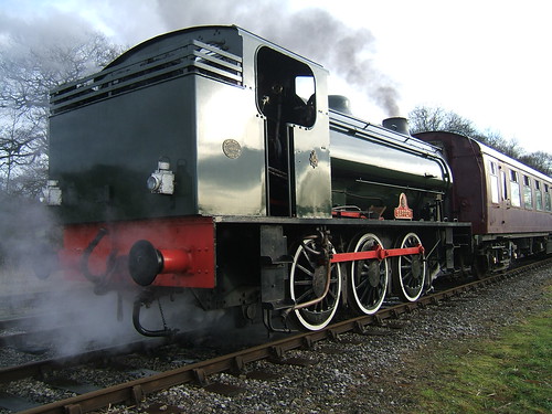
I had one day driving the 'Santa Specials' at The Battlefield Line on Saturday 17th December 2011. The special timetable called for four departures from Shackerstone at 10:00, 12:00, 14:00 and 16:00 each giving a round trip to Shenton, with a stop at Market Bosworth on the outward journey. Danny was 'marked' as Fireman with Sam (now almost-qualified as a fireman) and the locomotive was 3803, so I was pretty sure in advance we'd have a good day and so we did. It was only my second 'turn' on this engine - the first one is described here. This earlier post includes some background on these engines.

It was a cold morning with a hard frost and still dark when I arrived at the shed at 06:30. The big doors were open and 3803 wasn't immediately visible as she was boxed in by a diesel shunter but making itself known by the smoke lazily drifting at roof level. Danny and Sam had already checked the firebox, cleared both grate and ashpan and a new fire was taking hold.

It's second nature to check that the engine is secure (handbrake hard on, regulator shut, reverser in mid-gear and cylinder drain cocks open). I also satisfied myself that there was sufficient water showing in the gauge glass. It's not that you don't trust your mates, it's part of the relentless culture to ensure safety on railways. Opening the firedoors showed a sluggish fire but Danny and Sam had matters well in hand and additional wood soon got the fire away.

This left me free to oil round and carry out the daily 'Exam' of the engine. Although the shed had a number of fluorescent lights, the part you're checking always seems to be in shadow so I used a wind-up LED torch as I made my way round the engine. I always feel rather guilty that I'm not using a 'Duck Lamp' which was the type of hand-carried flare lamp traditionally used by enginemen. When I was at Tyseley Railway Museum, I used 'Duck Lamps' fairly frequently for authenticity, if not convenience.

Once I'd finished using the pit to access the underside of the locomotive, it would have been nice to drag 3803 outside with the diesel shunter but it was clear, from the brief 'eeeergh' from the starter motor as as Danny attempted to start the diesel engine, that the battery was not up to the job. I decided that, once we'd sufficient pressure to move the engine, we'd propel the diesel shunter through Platform 1 to the north end and stable it there, out of the way. A steam locomotive will move at much less than the nominal boiler pressure (225 p.s.i. for '3803') but, at low pressures, you may have to rely on the tender handbrake to control the movement. Danny travelled on the shunter, to keep a lookout ahead, Sam stood ready by the handbrake and we gently propelled the diesel shunter to the north end. Danny 'tied down' the shunter and 'unhooked' it from '3803' and we slowly made our way back to the platform.

We were soon ready to move across to our train in Platform 2 to start steam heating the coaches ready for our ten o'clock departure, but the signalman was initially reluctant to authorise the move as the Train Staff had not been located and a prior Engineering Possession on the single line had not been 'signed off' as withdrawn. After some delay, we 'got the road' to shunt across to our train - five coaches plus a 'BG' serving as "Santa's Grotto" as the last vehicle.

We 'hook-on', Sam starts the steam heating and I create vacuum so that the Guard can carry out a 'Brake Continuity Test'. When I see the 'Train Pipe' needle of the duplex vacuum gauge drop away and then come up again as the ejector re-creates vacuum, I know the test has been carried out. This should be done by unseating the vacuum hose from the 'stopper' on the rear coach so that the Guard is confident that the flexible vacuum hoses on all vehicles have been correctly coupled-up.

Tickets for 'Santa' trains are pre-booked and Stewards are provided with lists of passengers to check-off as they arrive. This means that departure times are only approximate if we're waiting for missing passengers so we were a little late getting the 'rightaway' for the first train.

Lever reverser into full back gear (we're running tender first to Shenton), whistle, handbrake off, ease the regulator partly open and gently move away, the front of the engine wreathed in clouds of steam from the open cylinder drain cocks. The use of drain cocks is not quite so crucial on engines with slide valves ('flat' valves), since the valve can move away from the cylinder port face to help clear any water from the cylinder but '3803' has piston valves. Piston valves are intended to be tight-fitting by the use of piston rings and so agressive use of the drain cocks when starting away after standing for any time is essential to avoid possible damage from trapped condensate.

I always 'link-up' very early. With the light loads encountered on preserved railways, once the train is moving there's little need to develop maximum torque so I believe in 'notching-up' by moving the reverser a few notches towards 'mid gear'. The term 'link-up' derives from the fact that, with a conventional arrangement of Stephenson Link motion, the expansion link is in its lowest position with the reverser fully forwards selecting 'forward full gear' so lifting the link will produce an earlier cut-off of steam during the piston stroke and hence use the steam expansively. Of course, if you're running tender first, you're actually lowering the link from the 'full back gear' position but it's still called 'linking-up'. There's a diagram illustrating the layout of the valve motion of '3803' in the earlier article referred to above.

Now we can shut the drain cocks. Great Western engines have about the best control for the cylinder drain cocks that I know. The cocks are opened by pulling back a handle which rises only a few inches above the cab floor. The handle is retained in the 'back' position by a pivoted catch working in a ratchet. To close the cocks, you stamp on the end of the pivoted catch which disengages it from the ratchet and allows the handle to move forward, snapping the drain cocks closed.

There's a 5 m.p.h. restriction over the crossover by the box so we keep going gently until we've collected the single line staff from the 'Bobby' on the landing in the signal box steps and the whole train has passed the '5' restriction sign applying to the opposite direction. I give her a little more steam, but we still have a 10 m.p.h. restriction until the train has passed under the first bridge. We're in no hurry with a 'Santa' train, because it takes some time for parties of children to be led back to the Grotto at the rear of the train to visit Santa, so I just open the regulator to 'Full First Valve' and let her run for a while. Most preserved railways have a Line Speed Limit of 25 m.p.h. so, providing the boiler is somewhere near the 'sizzling point', the settings I'd chosen would produce around that speed.

'Sizzling point'? I'd mentioned this in an earlier post on locomotive '813'. The Great Western were never seduced by the attractions of Ross Pop safety valves and always used their version of the early Ramsbottom design. This lets you bring the boiler pressure close to the blowing-off point with just a wisp of steam continuously escaping from the safety valves, in true Great Western fashion, rather than having the intermittent wasteful (and often noisy) discharge typical of Ross Pop safety valves. It was a point of honour amongst Great Western fireman to 'balance' the boiler with the valves just 'fizzing' to indicate to your driver (and everybody else) that you were on top of the job. Even when I was at Tyseley Railway Museum, if the pressure gauge was more than 10 pounds below the red line on a Great Western engine, the old-time enginemen would enquire "What's the matter? Won't she steam?".

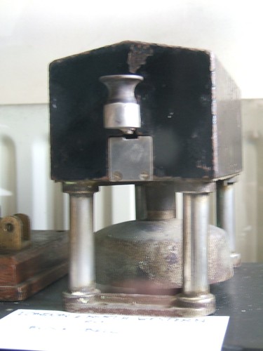
As we approached Headley's Crossing, I shut off and allowed the engine to drift towards the 10 m.p.h. 'slack' over the relaid track. Drifting on a Great Western engine with a Sight Feed Lubricator is a bit more complicated than shutting the regulator (and finding the best setting for the reverser) - the regulator is deliberately not quite closed against the stop so as to maintain lubrication to the cylinders and valves. The earlier article referred to above discusses the Sight Feed Lubricator and has a link to full details in Great Western Circular 5801. The photograph below shows the regulator complication. Above the regulator, there's a curved, slotted link, pivoted on the left. The regulator handle has an extension piece (extending upwards at about one o'clock in the picture), the top of which is pinned to the slot in the curved link. The slot is 'Z' shaped at the right so that initial movement on opening the regulator lifts the right hand side of the curved link but further movement produces no additional lifting action. The lifting of the link is communicated via a link (almost-vertical, red-painted) so as to open a steam valve mounted on the boiler backhead below the regulator. This valve is called the Jockey Valve or, sometimes, the 'W Valve' (because it's referred to as item 'W' in Circular 5801). The Jockey Valve controls the supply of steam to the Sight Feed Lubricator which, in turn, controls the supply of oil to the 'front end'. Thus, if the engine is being worked or 'drifting' (with a breath of steam or no steam), oil is being fed to the cylinders and valves.

Jan Ford on the footplate of '3803' (well wrapped-up against the cold and having reverted to her battered 'Grease-top').

A vacuum brake application (at 15 in/Hg) was also necessary to ensure that we passed the '10' board at the right speed. Once the whole train had passed the '10' board for the opposite direction, I re-applied steam until we had passed the out-of-use 2-aspect colour-light distant for Market Bosworth, where I shut-off again. Another brake application brought us down to 10 m.p.h. at the points on the approach to the station and we ran along the platform to come to a stand with the leading coach just at the top of the platform ramp. I shut the regulator fully so that the Jockey Valve stopped the oil feed to the front end and opened the drain cocks. There's a variable length stop here, according to how well Santa is getting on with meeting all the children, so Sam wound on the tender handbrake and I put the reverser in Mid-Gear and shut down the vacuum ejector to save steam (and make the footplate a bit quieter).

Once we were told that they were ready to depart, I created vacuum and heaved the reverser into full back gear. On receiving the Guard's 'Rightaway', I whistled, Sam released the handbrake and I eased the regulator open. Soon, I'd linked-up and closed the drain cocks. We kept a very sharp look-out over the foot crossing (although the station was closed to passengers) and waved to the restoration crew working on the Signal Box. They'd got the newly-completed stove going in the box. There's a 5 m.p.h. slack over the bridge in a few hundred yards so we kept going nice and easy until we were past the restriction, then it was full first valve to let her accelerate up the bank and back to drifting to come over the top and roll down the other side to Shenton. Gentle braking from the fixed distant signal to come over the points at 10 m.p.h. and along the platform, keeping a sharp look-out for people straying onto the foot crossing then bring the train to a halt with the leading coach just on the platform ramp. Danny uncoupled us from the train and we ran round.

Soon we were on the way back, chimney leading. No stop was required at Market Bosworth, so we just drifted through at 10 m.p.h. before steaming up the bank until the 10 m.p.h. slack over the relaid track. Steam on again until the old platelayers' hut on the approach to Shackerstone and then bring the speed down to both comply with the 10 m.p.h. slack at the road overbridge and be able to stop at the outer home signal, if needed. You can't sight the outer home until you come under the bridge - it was against us so I gave a long whistle. The signal soon came 'off', the arm threatening to go right over the top but settling down pointing almost vertical (reminding me of 3-aspect semaphore signals) so we didn't come to a stand. I gave a little 'pop' on the whistle to say 'thank you' and we rolled down the cutting. More braking was needed to comply with the 5 m.p.h. restriction over the crossover and the 'top dolly' of the ground signal came off, routing us over the crossover into Platform 1. Danny surrendered the staff to the signalman who verbally authorised us to "Pass the Stop Board to Run Round". This meant we could take the engine beyond the 'Stop Board' at the end of the platform and come to a halt with the leading vehicle (Santa's Grotto) just at the top of the platform ramp. One trip down - three to go!

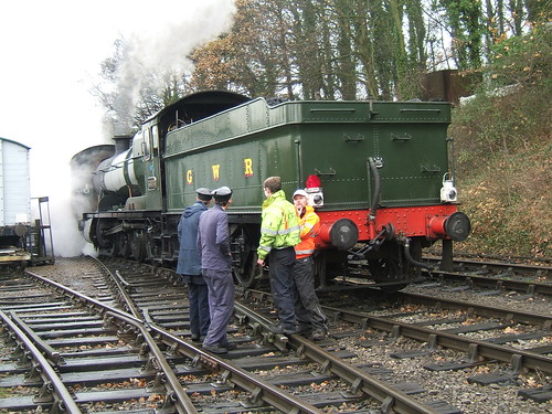
Danny, Sam, Andy and Ross in earnest discussion at Shackerstone. The left hand loco lamp is wearing a 'Santa' hat.

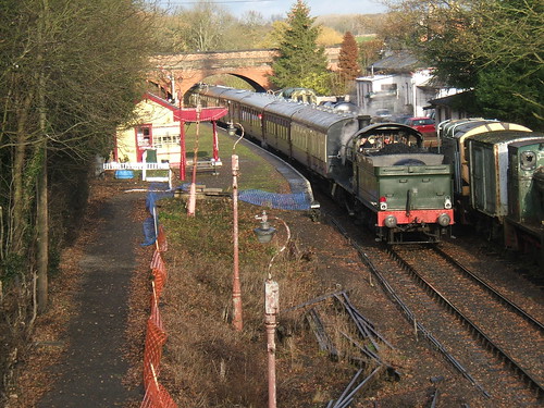
We ran round our train ready for the second trip. Again, there was delay awaiting passengers. Apparently, there'd been a Road Traffic Accident on the A5 because a number of passengers phoned in to say they were delayed. Eventually, we got the 'Rightaway' and made our way fairly gingerly out of Platform 1 and over the crossover. The journey to Market Bosworth was uneventful but we were told we'd stand there for at least half an hour, so I accepted an invitation to go and look at the restoration work on the signal box. I was very impressed with the work on the structure and took a number of photographs, including this elevated view of the station:-

A 'Santa Special' at Market Bosworth, viewed from the scaffolding around the signal box.

When the guard announced that he was ready to take the train out, a whistle from the engine (as arranged) brought me running back to the footplate and we set off for Shenton. Although the day was still cold, the sun was out and it was quite pleasant, except on the footplate where the wind was quite chilling, particularly running tender first. The 3,000 gallon tender might give you better visibility tender first but it gives you very little protection from wind and rain. We completed the second round trip without incident, arriving back in Platform 1 again and running round for the third trip.

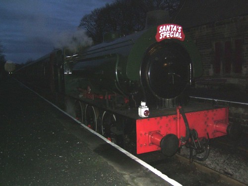
By this time, the weather had deteriorated and it was raining fairly hard, reminding me of my dictum "Anybody can work on engines in good weather - it takes railwaymen to do it in bad weather". Sam was tucked in the front corner of the cab, next to the warm boiler backhead to keep out of the worst of the weather, but Danny and I remained more exposed, trying to keep a good lookout. When we ran round at Shenton, we also lit the two engine lamps - although it was only around three-thirty, it had become really murky. At least the cab was more effective returning to Shackerstone but I found I had to lean out of the side of the cab or keep the front spectacle open to maintain a reasonable view ahead. Once again, we were routed into Platform 1 but, this time, we stopped to take take water at the column. Adrian provided a 'dose' of water treatment and suggested that we fill the tender tank to capacity.

By the time we were backed up on our train, we were already past the published departure. This train was not loaded to capacity so we didn't have to wait long before we got the 'Rightaway'. It's a completely different experience in the dark. In the steam era, British trains never carried high-intensity headlights although many foreign railways did. Everybody's familiar with pictures of American wood-burning 4-4-0s with a diamond stack and a huge rectangular headlamp but, in Britain, the head lamps performed the same task at night as in the daylight merely indicating the class of train.

The only light on the footplate was usually from a gauge lamp mounted near the gauge glass to assist the fireman in confirming the boiler water level. We had a working gauge lamp on the bracket next to the gauge frame. I'm afraid our gauge lamp was burning paraffin. In the old days, the gauge lamp always used rape oil which, being less volatile than paraffin, was less likely to explode into flames in its warm location next to the boiler backhead. In addition, a paraffin handlamp was often carried. With a white shade, it could be used when coupling, uncoupling, examining parts of the engine or just to help when walking about 'on the floor'. At night, a white light would be shown to the Guard in acknowledgement of his 'Rightaway'. We didn't have such a handlamp with us but used electric torches to acknowledge the Guard.

When the fireman opens the firedoors to shovel in more coal, the footplate is bathed in an orange or white light, depending how hard the engine is being worked. The driver will do well to protect his eyes from the glare, otherwise his night vision can be lost for a while. Some locomotives (particularly L.N.E.R. examples) were provided with a hinged shield to reduce the glare spilling across to the driver.

It wasn't completely dark as we made our way down the line for the last time. Some lineside features could still just be distinguished in silhouette against the inky sky. At night, sounds take on a more important role. The old drivers could work a train virtually 'with their eyes shut', listening to the distinctive sounds made by every rail joint, bridge and passing feature. We reached Market Bosworth safely, pausing briefly for the last time, then continued to Shenton. Uncoupling and coupling becomes more difficult in the dark and, when shunting through pointwork, it's vital that particular care is taken before moving points and that any handsignals given by lamp are clearly understood.

We ran round without incident and, having seen the Guard's green 'Rightaway' and acknowledged with a white, we set off back to Shackerstone. This time, we were routed into Platform 2. We lost no time in 'unhooking' and dropping forward clear of the points but then we had to wait a short while to allow the disembarking passengers to cross in front of us using the sleeper crossing at the end of the platform. We set back to the Ground Frame controlling access to the shed and, once called back by Danny, moved into the shed. Once the fire was cleaned and the boilers was filled, we were almost finished. By now quite tired, we made our way back to the station where I completed the repair sheet and signed off. Danny, Sam and I agreed we'd had an enjoyable, if tiring day.

My pictures taken on the day are here.
My pictures of the restoration of the signal box at Market Bosworth are here.
More pictures of 3803 are here.
Sam Brandist has his own blog - Sammy's World.

Friday 16 December 2011

Single-stroke Bells

When railways introduced the Block System for the control of trains, electricity was used to power the bi-directional single-stroke block bell between adjacent signal boxes and the galvanometers used as block indicators. There's a brief description in the post on L&NWR Block Signalling Instruments. As explained there, many railways used separate wooden-cased units for the Block Bell, the 'Pegging' Block Indicator and the 'Non-pegging' Block Indicator. The picture below shows the typical appearance of the block bell.

Wooden-cased single stroke bell at Shackerstone Railway Museum. Note the studio portrait in the background of a proud railwayman in uniform

However, the L&NWR developed a 'Combined' Block Instrument, joining Bell and Block Indicators into a single unit. But there were still applications for single-stroke bells alone, where the Signalman exchanged bell codes with, for instance, a Guard or Shunter at a Ground Frame. The picture below shows an early form of the L&NWR single-stroke bell mounted on a cast frame.

L&NWR single-stroke bell (early version) at Shackerstone Railway Museum.

Later versions used a larger housing with the bell tapper moved to a central position and replaced the cast frame with four round, hollow columns. The hollow columns copied the technique used on the later 'Combined' Block Instruments which offered a neat way of bringing the wiring from the block shelf into the bell housing.

L&NWR single-stroke bell (later version) at Crewe Heritage Centre.

Only one wire is required between the two bell units - an earth-return is usually adequate. Each key or tapper has one changeover contact. In the quiescent state, the incoming wire at each end of the line connecting the two bell units is fed to one end of the bell coil and the other end of the coil is earthed. When the key is operated, the local coil is disconnected and a suitable voltage from an earthed battery is fed to line, operating the bell coil at the remote end of the line. The coil forms an electromagnet which attracts a moving armature connected to a bell hammer. The ball at the end of the armature strikes the bell dome to produce the sound. A spring attached to the armature returns the bell hammer to its rest position against an adjustable stop when the bell coil is de-energised.

There was a single-stroke bell of the later version between Sedgeley Jn. and Conygree Sidings Ground Frame. One day fifty years ago I sketched some of the dimensions:-

Sketch showing the principal dimensions of the later form of the single-stroke bell.

I also sketched the rear base casting which mounted the rear two columns. It had a tapped projection for fitting an adjustable back stop for the bell hammer:-

Sketch showing bell hammer adjustable back stop at rear of unit.

Tuesday 13 December 2011

Jan's Train Register Book

In 2011 I scanned 'my' train register and, although there were some errors, posted it on the 'Scribd' site. However, it was removed from the site after a while (presumably because of low readership). I'm afraid it's taken me until 2021 to re-instate these pages (this time using Google Drive). The incorrect page 2 and various other editorial errors have not yet been put right, sorry.

I've now located one of 'my' train register books with details of most of the 'observations' I made between September 1963 and November 1965. Wolverhampton Power Signal Box had been commissioned on the 13th and 14th August 1965 so after this date Stour Valley signalboxes had either been abolished or downgraded to Shunting Frames. I think there should be an earlier train register book but I'm afraid this hasn't come to light.

This post is an index of the dates and locations covered by the train register, with links to the train register. The register pages are divided into two PDF files. 'Binder1.pdf' here and 'Binder2.pdf' here.

Location Date Register Pages
Deepfields Saturday 28th September 1963 2,3
Bloomfield Jn. Saturday 19th October 1963 2,3
Bloomfield Jn. Saturday 26th October 1963 4,5
Bloomfield Jn. Saturday 2nd November 1963 6,7
Bloomfield Jn. Saturday 9th November 1963 6,7
Watery Lane Saturday 16th November 1963 8,9
Watery Lane Saturday 23rd November 1963 10,11
Deepfields Saturday 30th November 1963 12,13
Watery Lane Saturday 14th December 1963 12,13
Bloomfield Jn. Friday 27th December 1963 14,15
Bloomfield Jn. Saturday 4th January 1964 16,17
Bloomfield Jn. Saturday 11th January 1964 18,19
Bloomfield Jn. Saturday 18th January 1964 18,19
Deepfields Saturday 1st February 1964 20,21
Deepfields Saturday 29th February 1964 22,23
Deepfields Saturday 7th March 1964 22,23
Deepfields Saturday 14th March 1964 24,25
Sedgeley Jn. Wednesday 25th March 1964 26,27
Sedgeley Jn. Saturday 28th March 1964 26,27
Sedgeley Jn. Saturday 11th April 1964 28,29
Sedgeley Jn. Saturday 25th April 1964 30,31
Deepfields Saturday 2nd May 1964 32,33
Deepfields Friday 15th May 1964 32,33
Deepfields Saturday 30th May 1964 34,35
Deepfields Saturday 6th June 1964 34,35
Tipton Curve Saturday 13th June 1964 36,37
Deepfields Saturday 20th June 1964 36,37
Sedgeley Jn. Saturday 4th July 1964 38,39
Deepfields Saturday 11th July 1964 38,39
Deepfields Saturday 25th July 1964 40,41
Deepfields Saturday 1st August 1964 40,41
Bloomfield Jn. Friday 2nd October 1964 42,43
Tipton Sta. Friday 2nd October 1964 42,43
Tipton Sta. Wednesday 7th October 1964 42,43
Tipton Sta. Saturday 10th October 1964 44,45
Deepfields Saturday 17th October 1964 44,45
Deepfields Saturday 24th October 1964 46,47
Deepfields Saturday 31st October 1964 46,47
Tipton Curve Jn. Saturday 7th November 1964 48,49
Deepfields Friday 13th November 1964 48,49
Deepfields Saturday 28th November 1964 50,51
Deepfields Saturday 5th December 1964 50,51
Deepfields Saturday 19th December 1964 52,53
Deepfields Saturday 2nd January 1965 54,55
Deepfields Saturday 16th January 1965 54,55
Deepfields Saturday 30th January 1965 56,57
Deepfields Saturday 13th February 1965 56,57
Bloomfield Jn. Saturday 6th March 1965 58,59
Deepfields Saturday 27th March 1965 60,61
Tipton Curve Jn. Saturday 27th March 1965 60,61
Deepfields Saturday 10th April 1965 62,63
Deepfields Tuesday 20th April 1965 62,63
Deepfields Saturday 24th April 1965 64,65
Deepfields Saturday 8th May 1965 64,65
Deepfields Saturday 22nd May 1965 66,67
Tipton Curve Jn. Saturday 29th May 1965 66,67
Deepfields Saturday 5th June 1965 68,69
Deepfields Tuesday 8th June 1965 70,71
Deepfields Saturday 12th June 1965 70,71
Deepfields Saturday 19th June 1965 72,73
Deepfields Saturday 26th June 1965 72,73
Watery Lane Saturday 26th June 1965 74,75
Deepfields Saturday 3rd July 1965 76,77
Tipton Curve Jn. Saturday 10th July 1965 76,77
Tipton Sta. Saturday 10th July 1965 78,79
Tipton Curve Jn. Saturday 17th July 1965 80,81
Deepfields Saturday 24th July 1965 80,81
Tipton Curve Jn. Saturday 31st July 1965 82,83
Deepfields Saturday 7th August 1965 82,83
Tipton Shunting Frame Saturday 28th August 1965 84,85
Bloomfield Jcn. Shunting Frame Tuesday 31st August 1965 84,85
Watery Lane Shunt Frame Saturday 4th September 1965 84,85
Tipton Station Shunt Frame Saturday 18th September 1965 86,87
Bloomfield Jn. Shunt Frame Saturday 2nd October 1965 86,87
Bloomfield Jn. Shunt Frame Saturday 6th November 1965 86,87


[Note about 'Scribd' added 29-Oct-2016: links to PDFs re-instated 06-Mar-2021]

Traffic Movements at Tipton Curve, 1965

There's an introduction to Tipton Curve box here.

Tipton Curve, Saturday 22nd May 1965

In this case, I've located my Train Register covering these movements and a copy appears after the text. The original notes appear in italics with minimal editing, sometimes followed by my recent comments attempting clarification. The numbers in brackets have been added purely to assist in locating entries.

(1) '37' Up - Train of empty Iron Ore very fast, Class 8 tender first.
(2) A special of Ore goes 'down the Vale'.
(3) 'T23' comes from Bloomfield, with 350 h.p. diesel electric, cab leading, HG, Lowside and two tenders with sludge. The guard is on the footboard of the brake, waiting to 'unhook' but the train goes 'almost to Princes End' with an unfamiliar driver! The Engine and Brake returns to Bloomfield.
(4) Later in the day, when we re-open, a Trolley is being pushed 'Bang Road' from Tipton with an S & T Bridge Girder. No signal box knows anything so we stop him and make him clear our Track, to let us have an Electrification train down for Bushbury - engine, LMR Brake, Well Wagon loaded with transformers, Crane, Match Truck and BR Brake.

Monday 12 December 2011

Santa Specials at Peak Rail 2011

I was steam locomotive driver on the 'Santa Specials' at Peak Rail on Saturday 10th December 2011. The schedule called for four round trips from Rowsley to Matlock Riverside with a maximum-length 7-coach train. The working was to be top-and-tailed with a steam locomotive at the south end and a main-line diesel electric at the north end.

Peak Rail stalwart 68013 is currently undergoing boiler work so 'Lord Phil' was originally planned to perform the steam diagram. Unfortunately, 'Lord Phil' has recently been 'stopped' for attention to the axleboxes. Fortunately, at short notice, Peak Rail was able to hire another 'Austerity' tank - 'Sapper' from the East Lancashire Railway.

'Sapper' on the outside pit at Rowsley being prepared for duty.

I'd not worked on 'Sapper' before and it's always interesting to have a different locomotive. Even though all 'Austerity' tank locomotives share the same basic layout, there's considerable variation in detail between different restored locomotives. I quickly formed the impression that the locomotive had received a competent and thoughtful restoration and I was not disappointed.

'Sapper' was 'brewing up' on the outside pit and Dave (Fireman) and the Cleaner had matters well in hand when I arrived (a little late because of a road traffic accident on the A6). I completed the 'oiling round' and daily examination then we moved the engine to the siding alongside the shed so that Chris could use the Bucket Loader to top-up the bunker with coal. 'Sapper' is provided with coal rails on the bunker so we were able to take a generous tonnage.

At the scheduled time of ten o'clock, we moved the engine across to the 7-coach train standing in the platform. Since the first departure was scheduled for 10:45, I was a little concerned that we'd seen no sign of a diesel locomotive crew, let alone any sign of the rostered locomotive, 'Penyghent', being drawn out of the shed for starting. I warned the fireman to be prepared to work the first train unaided.

We started to warm the coaches and we were delighted to find that we could set the carriage heating steam pressure to the specified 30 p.s.i. and it stayed as set. Since industrial locomotives didn't originally have carriage warming facilities, this facility is added during restoration and inappropriate control valves are sometimes employed, resulting in difficulties controlling the output.

Industrials also lacked vacuum brakes originally so, again, a variety of approaches may be found when this feature has been added. 'Sapper' retained the original arrangement of a steam brake valve mounted on the fireman's side, with a horizontal shaft across the cab with handles for applying the brake within reach of both fireman and driver. A 'Davies and Metcalfe' ejector had then been added in front of the driver for creating and applying the vacuum brake on the train but this is not a 'Combination' brake as would normally be fitted to passenger engines with steam brakes on the engine. In a 'Combination' brake, application of the vacuum brake will automatically proportionately apply the steam brake to the locomotive. Since 'Sapper' lacks this refinement, it may be advisable for the driver, when stopping a train with the vacuum brake, to also make a steam brake application to prevent the locomotive from 'bouncing' against the train as it comes to rest.

I decided to assume that we were 'going on our own' and I carried out a functional vacuum brake test on the 7-coach train. First, 21 in/Hg of vacuum is created in the train pipe which should ensure that all train brakes are off. This vacuum is destroyed and the length of the train is inspected, ensuring that all brake blocks are 'on' (or, rather, that all brake blocks on the non-platform side of the train are 'on'). If this is satisfactory, vacuum is re-created and the whole train is inspected again to ensure that all brake blocks are now 'off' and clear of the wheel tyres, with the exception of the Guard's Brake composite coach, where the Guard's Handbrake will keep the brakes applied. In this case, correct operation of the vacuum system can be determined by ensuring the the piston in each brake cylinder is 'up' when the vacuum brake is applied and 'down' when the vacuum brake is released.

While all this was going on, the locomotive had been feeding steam for carriage warming. It takes a while for this steam to work its way through the train and the cleaner had opened the steam heating shut-off cock on the rear coach to assist the process. Eventually, clouds of steam vented from the the steam heating hose on the rear coach, indicating that steam was passing throughout the train. I was intending to shut the open cock on my second walk testing the brakes, but the Guard just beat me to it.

We heard that the diesel crew had failed to start 'Penyghent' because of battery problems and that an attempt was being made to start the Class 31. We were asked to take the first departure on our own, which we were happy to do, since the destination was Matlock Riverside (where we could run round our train for the return journey), not Matlock Town. For the Santa trains, only Rowsley station is used by passengers and seats are pre-booked for a round trip.

On receipt of the Guard's 'Rightaway', we set off with our seven coaches. 'Austerity' tanks are powerful locomotives so a trailing load of around 250 tons barely taxes the engine which can be worked quite lightly. Church Lane's Up Home signal was already off as we approached and we surrendered the Church Lane-Rowsley single line staff to the 'Bobby' as we passed the box. Soon, we were braking for our booked stop at Darley Dale.

'Sapper' pauses at Darley Dale with the first Up service of the day.

The crossing gates opened, the bracket signal came 'off', the Guard gave the green flag and we were off again, collecting the Darley Dale-Matlock single line staff from Signalman Jack Hinks as we passed. Our progress to Matlock Riverside was quite restrained - there's currently a ten miles an hour 'slack' (speed restriction) most of the way. Although there was some snow on the hills, the valley we were running in was free of snow. The sun was out and it was a pleasant day, apart from the bitter wind blowing straight into the cab on the driver's side.

We made a gentle approach to Matlock Riverside where there's a temporary speed restriction of 5 m.p.h. whilst the re-signalling work is in progress. We came to a stand fairly well along the patform - there's not much margin for error at Matlock Riverside when running round seven coaches but we had no problem and were soon 'tied-on' to the train for our bunker-first run back to Rowsley.

The trip back to Darley Dale was uneventful and I intentionally stopped with the leading coach clear of the platform. Six coaches will fit in the platform but longer trains need to stop further forward to avoid complaints that the rear of the train is still occupying the track circuit protecting the facing points.

'Sapper' ready to leave Darley Dale on the first Down train of the day.

We headed back to Rowsley still unaware of whether the 'Class 31' would be ready to join us. As we approached the station, we could see the '31' in the headshunt, beyond the 'END OF SINGLE LINE' board. We uncoupled from our train and, having confirmed that the diesel would stay where it was until we were clear, dropped forward clear of the loop handpoints and run round the stock.

The remaining three round trips of the day were 'top-and-tailed', as originally intended but with the '31' substituting for 'Penyghent'. We lit the paraffin engine lamps for the last trip - it was already getting dark. We carried two white lights, one above each buffer, on our way to Matlock (signifying an express). To return, I removed one white lamp and inserted the red shade in the other so that we were carrying the required tail lamp.

The last train of the day standing at Darley Dale before being hauled back to Rowsley by the '31'. Note the red tail lamp on the buffer beam.

Every train was filled to capacity during the day. Commercially, the 'Santa Specials' are very important to most preserved railways. But I hope people find them good fun as well - I do.

Tuesday 6 December 2011

List of Traffic Movement Posts

I've written a number of posts describing some of the railway traffic movements in the West Midlands in the 1960s. Most of the observations are based on working (unofficially) in signal boxes. As I've located my original rough notes, I've written them up as this series of posts (as time permitted). Some of the posts cover many hours of observation, some are merely fragments. The tables below list these posts in date of observation, earliest first. I've separated posts covering the Stour Valley Line from those at Sedgeley Junction on the South Stafford Line. Links in the last column should get you to the individual posts.

Stour Valley Line

Location Date Click on link
Journey May 1960 Steam Special
Watery Lane Tuesday 17th October 1961 Stour 2
Watery Lane Saturday 4th November 1961 Stour 2
Watery Lane Thursday 16th November 1961 Stour 3
Watery Lane Saturday 2nd December 1961 Stour 3
Tipton Monday 29th January 1962 Stour 3
Dudleyport Saturday 17th February 1962 Dudleyport
Bloomfield Jn. Saturday 24th March 1962 Bloomfield Jn. 1
Bloomfield Jn. Saturday 7th April 1962 Bloomfield Jn. 1
Journey Tuesday 19th June 1962 Sunday Stroll
Bloomfield Jn. Saturday 28th July 1962 Holiday Time
Bloomfield Jn. Saturday 11th August 1962 Bloomfield Jn. 1
Dudleyport Friday 24th August 1962 Dudleyport in the Dark
Watery Lane Friday 12th October 1962 Watery Lane 1
Bloomfield Jn. Saturday 3rd November 1962 Bloomfield Jn. 2
Watery Lane Saturday 23rd November 1963 Reading the Runes
Bloomfield Jn. Friday 2nd October 1964 Traffic Movements
Tipton Station Friday 2nd October 1964 Traffic Movements
Tipton Wednesday 7th October 1964 Tipton
Deepfields Saturday 17th October 1964 Deepfields 1
Deepfields Saturday 24th October 1964 Deepfields 2
Tipton Curve Saturday 27th March 1965 Heaviest Load
Tipton Curve Saturday 22nd May 1965 Tipton Curve
Tipton Curve Saturday 10th July 1965 Tipton Curve

South Stafford Line

Location Date Click on link
Sedgeley Jn. Sat 8th December 1962 Sedgeley Jn. 2
Sedgeley Jn. Sat 15th December 1962 Sedgeley Jn. 2
Sedgeley Jn. Sat 22th December 1962 Sedgeley Jn. 3
Sedgeley Jn. Mon 24th December 1962 Sedgeley Jn. 3
Sedgeley Jn. Sat 29th December 1962 Sedgeley Jn. 4
Sedgeley Jn. Sat 12th January 1963 Sedgeley Jn. 4
Sedgeley Jn. Sat 26th January 1963 Sedgeley Jn. 4
Sedgeley Jn. Sat 9th February 1963 Sedgeley Jn. 5
Sedgeley Jn. An Evening in February 1963 Sedgeley Jn. 5
Sedgeley Jn. Sat 23rd February 1963 Sedgeley Jn. 6
Sedgeley Jn. Wed 20th March 1963 Sedgeley Jn. 7
Sedgeley Jn. Sat 23rd March 1963 Sedgeley Jn. 7
Sedgeley Jn. Friday 29th March 1963 Sedgeley Jn. 8
Sedgeley Jn. Monday 15th April 1963 Sedgeley Jn. 9
Sedgeley Jn. Saturday 20th April 1963 Sedgeley Jn. 10
Sedgeley Jn. Saturday 4th May 1963 Sedgeley Jn. 11
Sedgeley Jn. Friday 10th May 1963 Sedgeley Jn. 12
Sedgeley Jn. Saturday 18th May 1963 Sedgeley Jn. 13
Sedgeley Jn. Saturday 25th May 1963 Sedgeley Jn. 14
Sedgeley Jn. Monday 3rd Jun 1963 Sedgeley Jn. 15
Sedgeley Jn. Tuesday 4th June 1963 Sedgeley Jn. 16
Sedgeley Jn. Saturday 8th June 1963 Sedgeley Jn. 17
Sedgeley Jn. Friday 14th June 1963 Sedgeley Jn. 18

Monday 5 December 2011

Reading the Runes: Decoding Train Register Books

In the post 'The Train Register Book', I talk about the log books kept in signal boxes recording exactly what happens. But some of my friends have suggested that the bald list of timings is hard to make sense of. Let's look at a Saturday morning at Watery Lane back in 1963 to try to make things a little more clear.

Watery Lane after conversion to a Shunting Frame, still retaining the rather forbidding appearance of 'A.R.P.' boxes.

It's certainly important to understand the facilities provided at the signal box and have some idea of its relationship to the adjacent signal boxes. Watery Lane is described here. It may be useful to be able to refer to the Working Time Tables for passenger and freight trains, Freight Train Trip Notices and Special Traffic Notices but, for now, let's ignore that complication.

Ideally, you need to be familiar with the 'Regulations for the Signalling of Trains', the significance of all the bell codes and any special local regulations but, again, let's leave all this to one side for now. 'The Signal Box' is an excellent site for signalling information and all the bell codes then in use are listed here.

My train register book for the morning is shown below. Remember, the DOWN and UP pages are side-by-side in the train register book itself.

(Click on page for an enlarged view)

I booked on at 6.15 a.m., having travelled from Wolverhampton on the local train to Tipton and then walked to Watery Lane. The official signalman, my friend Tom, had booked on earlier and relieved the 'night man'.

The first train was a down local - a DMU. I accepted the train (a '3-1') from Dudleyport at 6.21, placed my block instrument at 'Line Clear', releasing Dudleyport's signals and immediately obtained 'Line Clear' from Tipton, allowing me to clear my Down signals. At this stage, I'd leave the Level Crossing Wicket gates unbolted, allowing pedestrians to continue crossing. Normally, these would be bolted on receipt of 'Train Entering Section' ('2') from the box in the rear. The road crossing gates at Watery Lane were always left open for rail traffic, unlike Tipton, where the gates had to be worked each time. At 6.23, the train started away from its Dudleyport stop and Dudleyport sent 'Train Entering Section' ('2'). I flipped the commutator to 'Train on Line' and sent 'Train Approaching' ('1-2-1') to Tipton. This is his cue to wind the gates and get his own down signals 'off'.

Around the same time, I accepted an Up express from Tipton ('4') and 'sent it on' to Dudleyport so that I can clear my Up signals. The Down local passes at 6.24 a.m. and the Up express two minutes later. Because of the short distance to Tipton, I wait for 'Train Out of Section' ('2-1') from Tipton before 'clearing back' to Dudleyport. On the Up, I give 'Train Out of Section' to Tipton at 6.26 a.m., as soon as I've a quarter of a mile clearance beyond my Up Home and Dudleyport 'knocks out' a minute later.

Five minutes later, I 'take on' a Light Engine ('2-3') on the Down Loop - the parcels engine returning to Wolverhampton for another train. There's 'nothing about' on the down so we 'turn him out' and he scuttles off to Wolverhampton.

At 6.57 Tipton offers an Up Local and at 7.0, Dudleyport has a Down Local. After these trains pass, there's another Up Express offered at 7.13. As he passes, Dudleyport offers pick-up freight T73 ('3') on the Down Loop. A Down Express is taken on at 7.23, so we have to let T73 come to a stand at our Down Loop Home Signal. The Down Express passes at 7.35 and the Up Local which has been 'on the block' since 7.30 passes at 7.38. At the same time, another Down Local is accepted from Dudleyport. After this local passes, there should be a margin for T73. We get 'Line Clear' from Tipton and 'Block Back ('2-4' Blocking Back Inside Home Signal) to Dudleyport to protect the freight as he stops and shunts in the Down Sidings at Tipton. At 7.59, Tipton offers an Up Local, which we refuse for 3 minutes. The most likely explanation is that T23 (the Tipton Shunt) wanted to draw out from the Up Sidings and then immediately push back on another road a raft of wagons too long to be shunted without 'coming out main line'. A 'running move' like this could fairly legitimately be done without 'Blocking Back' for protection. The Up Local passed at 8.04. Soon after Dudleyport had given 'Train Out of Section for this train, he 'Blocked Back' on the Up, possibly so that the Dudley Parcels could load or unload on the Up Platform for the convenience of the station staff. At 8.10 Dudleyport offered us a Parcels on the Down Main and as he sent 'Train Entering Section', he also cleared the 'Block Back' on the Up.

At 8.18 we 'take on a local on the Down and, a minute later, an Express on the Up. These pass us at 8.23 and 8.25, repectively. We refuse the Up Parcels at 8.37, accepting him a minute later. I assume this was because of T23 doing another 'main line shunt'. We 'get the road' for the parcels on the Up Loop but Tipton cancels the parcels at 8.42 and offers a following Up Local instead. So we cancel the Parcels on the Loop ('3-5') to Dudleyport and offer a '3-1' Up the Main instead. The Up Local passes us at 8.45. Presumably, Tipton realised that he hadn't time for the Up Parcels to complete its work in the platform and tuck itself in the Up Loop at Watery Lane without seriously delaying the Up Local. He had two possible ways of shunting the parcels out of the way - putting it 'across the road' onto the Down Main or setting it back onto the branch from Princes End. Since he didn't 'Block Back' to Watery Lane on the Down, I assume he set the train back onto the Branch, under protection of a '3-3' ('Blocking Back Outside Home Signal').

Shortly after the Up Local has gone, we 'Block Back' on the Up to Tipton, whilst T23 does some serious shunting main line, but we clear the 'Block Back' at 8.51 and accept the Up Parcels which this time goes up the Main to Dudleyport. At 8.52, we accept T42 from Tipton, which is routed up the Loop. On the down, we 'take on' a Local at 8.54 which passes at 9.00.

All is quiet for a while, until we accept a Parcels on the Up at 9.26, pass at 9.27 and at 9.40 a Down Express, pass at 9.49. At 9.52 we take on an Up Express which passes at 9.56. At 10.10, we 'Block Back' to Tipton for 9 minutes. The Local on the Down is briefly refused - I imagine because T23 is completing a 'running move' into the Down Sidings to be ready for a short journey to Bloomfield Junction. After Tipton has 'knocked out' for the Down Local at 10.23, we offer T23 as a Light Engine ('2-3'). The Up Express at 10.25 is briefly refused, presumably because fetching T23 out of the Down Sidings at the Watery Lane end will briefly foul the Up Main but there's no damage done and the express passes at 10.32. We take on another Up Express at 10.41 which passes at 10.44. T23 then returns on the Up, this time as an Engine and Brake ('1-1-3'), at 10.58. It looks as if he immediately starts shunting main line again as we Block Back to Tipton from 11.00 to 11.03.

On the Down, we accept a Local at 10.53 and receive 'Train Entering Section ('2') at 10.56. It appears that the Stockport Parcels has finished his work in the Bay at Dudleyport, and we get a '1-3-1' down the Loop at 10.57. After the Down Local, we 'get the road' for the Stockport from Tipton and turn him out main line.

Light Engine '0D97' passes on the Up at 11:21 and, a few minutes later, pick-up freight T90 comes down the Loop, to wait at our signal until the down express (taken on at 11.30) has passed. We turn out T90 but Block Back to Dudleyport (from 11.39 to 11.47) so I assume that T90 stopped at Tipton to attach/detach vehicles from the Down Sidings. Before T90 had finished, Dudleyport sent the 'Shunt' ('1-5-5': 'Shunt Train for Following Train to Pass'). We forwarded the 'Shunt' to Tipton who gave 'Train Out of Section' at 11.47 allowing us to remove the 'Block Back' also at 11.47 and accept a down train of Empty Coaching Stock ('2-2-1') which passed at 11.48. At 11.49 we accepted the Up Local from Tipton which passed at 11.56.

We accepted another down pick-up freight (T68) from Dudleyport at 12.04 and he passed at 12.09, to stop at Tipton. As soon as he'd passed, we 'got the road' on the Up Main for T23 light engine which had been waiting in the Down Sidings for a margin to return to shed (either Bescot or possibly Monument Lane). Meanwhile, T68 had presumably left his brake van main line and reversed his train into the Down Sidings at Tipton. He then returned to his brake van main line and, like T23, was anxious to scarper. Tipton put a 'Wrong Direction Movement' on the block ('2-3-3'). This can only be used where authorised but the complexity of the working around Tipton meant that such moves were authorised. So T68, Engine propelling his Brake, returned to Watery Lane in the wrong direction on the Down Main ('bang road') with Tipton maintaining his block indicator for the Down Main at 'Train on Line'. With T23 having scuttled off at speed, Dudleyport had already 'knocked out' on the Up Main, so I was able to offer T68 as a '1-1-3' ('Engine and Brake') to follow. Having obtained a 'Line Clear', I could reverse the crossover to turn the engine and brake onto the Up Main and away. A 'Wrong Direction Movement' is unusual in that there must be a means for the box at the opposite end of the section from normal to indicate that the section is clear. This is the '5-2' bell code - 'Train Clear of Section' which I sent to Tipton, who then altered his block indicator from 'Train on Line' to 'Line Blocked' so that I could offer further trains in the 'Right' direction.

Meanwhile, I'd 'taken on' an Up express from Tipton at 12.16 so I sent the 'Shunt' to Dudleyport for T68. As soon as T68 had cleared Dudleyport, I obtained 'Line Clear' for the express and cleared our Up signals. The Up passed at 12.21, as Dudleyport offered an express on the Down. At 12.27, I 'took on' a 'Special' up parcels from Tipton at 12.27 which passed at 12.30, a minute before the down express passed. At 12.36, I accepted the down local from Dudleyport. This passed at 12.40. The up local was accepted at 12.49, passing at 12.57. At 1.00, Dudleyport offered another down local (and gave 'Train Out of Section' for the previous up local).

I obtained 'Line Clear' from Tipton for the down local and, at this point, my register stops. I'd just about five minutes to leave Watery Lane and walk to Tipton station so as to catch the approaching down local back to Wolverhampton at the end of an interesting morning.