
However, the L&NWR developed a 'Combined' Block Instrument, joining Bell and Block Indicators into a single unit. But there were still applications for single-stroke bells alone, where the Signalman exchanged bell codes with, for instance, a Guard or Shunter at a Ground Frame. The picture below shows an early form of the L&NWR single-stroke bell mounted on a cast frame.

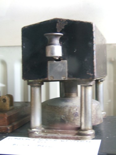
Later versions used a larger housing with the bell tapper moved to a central position and replaced the cast frame with four round, hollow columns. The hollow columns copied the technique used on the later 'Combined' Block Instruments which offered a neat way of bringing the wiring from the block shelf into the bell housing.
Only one wire is required between the two bell units - an earth-return is usually adequate. Each key or tapper has one changeover contact. In the quiescent state, the incoming wire at each end of the line connecting the two bell units is fed to one end of the bell coil and the other end of the coil is earthed. When the key is operated, the local coil is disconnected and a suitable voltage from an earthed battery is fed to line, operating the bell coil at the remote end of the line. The coil forms an electromagnet which attracts a moving armature connected to a bell hammer. The ball at the end of the armature strikes the bell dome to produce the sound. A spring attached to the armature returns the bell hammer to its rest position against an adjustable stop when the bell coil is de-energised.
There was a single-stroke bell of the later version between Sedgeley Jn. and Conygree Sidings Ground Frame. One day fifty years ago I sketched some of the dimensions:-
 Sketch showing the principal dimensions of the later form of the single-stroke bell.
I also sketched the rear base casting which mounted the rear two columns. It had a tapped projection for fitting an adjustable back stop for the bell hammer:-
 Sketch showing bell hammer adjustable back stop at rear of unit.
