Showing posts with label London Underground. Show all posts

Sunday, 11 April 2021

London Underground - Traction Power Distribution (2)

This article is a continuation of the topic London Underground - Traction Power Distribution

London Underground uses a fairly unusual fourth rail electrification system with a nominal voltage of 630 volts direct current (d.c.). At the time the system was being developed, the available insulation materials for traction motors made higher voltages problematic.

Normally, this voltage would be quoted at 'Full Rated Current'. But the current drawn from traction substations varies as trains start, coast, stop. Worst case is generally when two (or more) trains start away at the same time. The trip current on the High Speed Circuit Breaker feeding the positive rail at each sub station should be higher than the normal maximum current expected, otherwise 'nuisance tripping' can occur. But, of course, if a few thousand amps is being drawn by a traction section, there is a voltage drop on the track feed cables and the conductor rails so trains will experience a lower voltage which will change both according to the current drawn by each train and its position of the train in the traction section. The techniques of double end feeding, track paralleling and coupling of adjacent sections mean that a number of rectifiers may be contributing current to a single train. Although Kirchoff's Law allows you to work out the contribution of current from each rectifier, the situation will change second-by-second so, in general, all potential sources of current are paralleled to minimise voltage drop.

The nominal 630 volts d.c. is derived from incoming 11kV or 22kV 50Hz from the grid via transformers and semiconductor rectifier units. Nominal a.c. voltages are subject to variation as the load on the grid varies, also affecting the d.c. traction voltage.


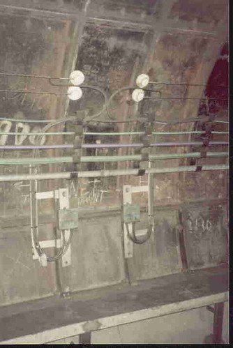
Suite of modern traction circuit breakers (negative breakers at Marlborough Road Traction Sub Station during installation in 2011)


General view of Baker Street Traction Sub Station.
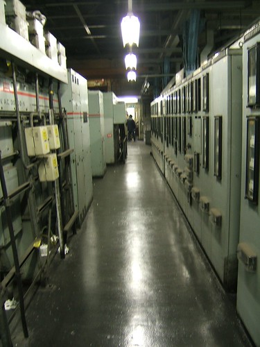

View inside a Acton Traction Sub Station on London Underground.

The fourth rail electrification system is nominally earth-free principally because the materials and construction used in early traction motors were prone to insulation failure introducing an earth. With earth-free distribution, it's possible to continue running if a train develops an earth or partial earth to either the positive or negative side of the supply. But you need to know about it, before a second train develops an earth to the other side and a High Speed Circuit Breaker detects an overcurrent and disconnects the supply.

As described in an earlier article, a potential divider of 220 ohms in series with 110 ohms is installed at the end of each traction sectionalisation to deliberately earth the traction with 220 ohms to the positive rail (outer), 110 ohms to the negative (centre) rail and the connection between the resistors earthed. Applying Ohm's Law to a nominal supply of 630 volts d.c. shows that each resistor takes a current of 1.909 amps and the positive rail sits at 420 volts positive to earth and the negative at minus 210 volts to earth (a 2:1 ratio). These voltages are only true if the 630 volts is nominal - as it goes up and down, the measured voltages to earth will go up and down, too. The voltages are only true if there is no connection to earth other than intentionally via the bleed resistors. In practice, the various spurious paths to earth may unbalance the ratio, offering a fairly simple means of monitoring the section for earth leakage. A system called 'TED' (Traction Earth Detection) is used to display the ratio at the Service Control Centre (formerly called Line Control Centre). If the ratio increases or decreases beyond preset limits, an alarm is automatically sounded to alert the Service Controller.


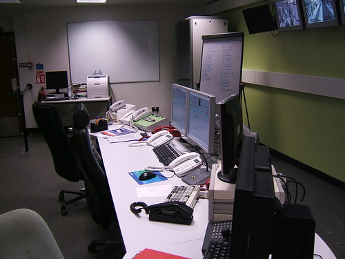
Traction Earth Detection (TED) equipment at the Metropolitan Line Service Control Centre.

To enable trains to increase demand on the traction distribution system (to support a combination of increased speed, increased service frequency and air conditioning requirements) all new equipment is designed to operate at 750 volts d.c. rather than 630 volts d.c. Operational changes are in progress to implement this change.

Related posts on this website

London Underground and Jan
London Underground: The Waterloo & City Line
Fourth Rail Electrification
London Underground - Traction Power Distribution

My pictures

There's a very patchy collection of pictures showing some of the London Underground lines on my 'Flickr' site (most of them are rather poor, I'm afraid). You can find them all here.
I've placed links to some of these albums below.

The various lines:-
Central Line.
White City (Central Line).
District & Circle Line.
Hammersmith & City Line.
Jubilee Line.
Metropolitan Line.
Northern Line.
Waterloo & City.
Service Control Centres (formerly Line Control Centres):-
District Line LCC.
Metropolitan Line LCC.
Waterloo & City (combined with general pictures).
Traction Sub Stations:-
Acton TSS.
Baker Street Substation.
Finchley Road TSS.
Marlborough Road Substation.

Monday, 5 April 2021

Railway Engineering Works, Acton


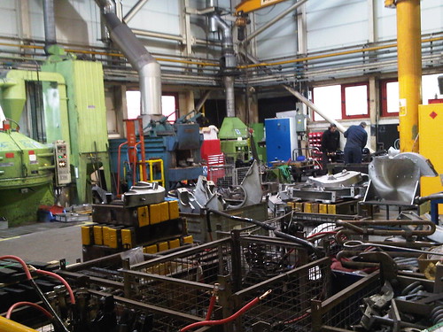
One corner of the Railway Engineering Works at Acton

Crewe, Swindon, Doncaster, Eastleigh, Acton - Acton? Perhaps Acton isn't one of the more famous railway works but London Underground established an important works at Acton. Mass transit sysytems are very intensively used and maintenance of rolling stock and infrastructure to the highest standards is essential.

My interest in Acton Works only started around 1995 when my firm became involved in work for London Underground, as described in the post London Underground and Jan. To be allowed 'behind the scenes' on any railway requires induction, safety training and various examinations matching the roles to be undertaken. An undergound fourth-rail electrified railway has particular risks and London Underground had a well-developed set of in-house training courses based at a Technical Training Centre at Acton Works. So I became a fairly regular visitor to Acton Works as I obtained different certifications and periodic re-certifications in connection with our work supplying Tunnel Telephone equipment, initially for the Jubilee Line Extension project and later for other London Underground lines. During these training visits, I saw glimpses of the work carried out around the sprawling Acton site, a mixture of old, modern and relocatable buildings.


Visits in 2006

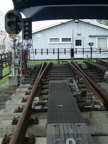
During visits to REW Acton in connection with the design and supply of Tunnel Telephone equipment for a new installation at White City (necessitated by major changes to the London Underground depot in connection with the building of Westfield London Shopping Centre), I was able to take pictures of the external Signalling Training Facility that had previously intrigued me. Nearer the original Bollo Lane entrance to the site, a large concrete base provided with a fabric roof mounted an array of full-size working signalling equipment, including signals (colour light and disc shunting), point machines and train stops. On London Underground, points and train stops are electrically controlled but use compressed air to provide power, so the normal features of an air main running alongside the track provided with electro-pneumatic controls were also fitted. This allowing Signalling Technicians to receive training in maintenance of the various types of equipment in use on London Underground in a realistic environment supplementing training given in the adjacent Signal Training School, a large relocatable building provided with examples of various types of control system.


Signal Training facility, Bollo Lane, Acton with a variety of signals and air-operated points. The air main and control cables are along both sides, carried on posts.


View in opposite direction of Signal Training facility. Left: Colour light signals Right: Turnout. The gabled building in the background is the Signal Training School.

Tour in 2011

During another business visit in March 2011, one of the London Underground staff arranged a fascinating, although brief, tour of part of the works. There wasn't time to get a proper understanding of the variety of work undertaken but I quickly realised the expertise available on the site. Below is a small selection of the things I saw.

Repair and refurbishment of rolling stock equipment forms a vital part of the work. In the reception area of one modern building, a part-sectioned motor wheelset for 1983 tube stock and part-sectioned gearbox for 92 tube stock were displayed.


Motor Wheelset for 1983 tube stock (part sectioned) on display at REW Trains Division, Acton.

In the Traction Motor Section of the works, rows of motors were being processed.


Traction motor section, REW Acton

Nearby, a series of massive jigs were provided for working on the pre-wired underbody control sub-assemblies.


Underbody control sub-assembly, mounted on jig.

Various signalling equipment is maintained at Acton, including heavy items like trainstops and various types of electro-mechanical relays.


Trainstop complete assembly, REW Acton


Shop for re-certifying electro-mechanical signalling relays (REW Acton)

I hadn't realised that surface-mounted cables feeding signalling equipment were normally pre-fabricated in standard lengths including moulded terminations, minimising time-to-exchange when replacement was necessary. I think these cables were bought-in complete but REW Acton also acts as a central stores for London Underground.


Prefabricated multicore cable for signalling showing moulded termination for fast connection to 12 terminal posts (REW Acton)

On an intensive mass transit system, every minute counts and London Underground has always provided clocks on stations to assist passengers and staff. But I was still surprised by the variety of clocks being repaired and regulated in the Clock Section. At the time of my tour, London Underground still had a few mechanical clocks at stations requiring weekly visits for winding!


The Clock Section (REW Acton)

Redundant D78 vehicles

During my 2011 visits, I saw a redundant D78 vehicle leaving the works on a low-loader. At the time, I thought the coach was going for scrap but I discovered afterwards these trains had been bought by Vivarail for conversion into modern, lightweight diesel-electric units for use on heavy-rail infrastructure. I caught up with these former D78 vehicles on a visit in 2018 to Quinton Rail Technology Centre (there's a post on that visit here).


Redundant D78 vehicle leaving REW Acton on low-loader in 2011.


My pictures

Pictures at REW Acton.

Books

There's a book on Acton Works titled ‘Underground Train Overhaul – The Story of Acton Works’ by J. Graeme Bruce/Piers Connor, published by Capital Transport Publishing in 1991 (ISBN 1 85414 134 1).

Wednesday, 7 October 2015

London Underground: The Waterloo & City Line

In my introductory post London Underground and Jan, I described how my interest in the Underground was sparked when my firm became involved in supplying tunnel telephone equipment.

One of the lines I've worked on is the Waterloo and City. At just under a mile and a half in length the Waterloo & City is the shortest of the London Underground railways now operated by Transport for London but it has a lot of interest.

In the post Waterloo Station, London (Part 2) I explained that the London & South Western Railway (L&SWR) which built the main line terminus at Waterloo had an ambition to extend their line eastwards. The Waterloo and City Railway Company was incorporated in 1893 by an Act of Parliament. Although independent from the L&SWR, no less than five of the eight directors of the new line were directors or employees of the L&SWR! Construction of the double-track Waterloo and City Line started in 1894 and it was opened, using electric traction, in 1898. It is 1 mile 46 chains long with two single-bore iron segment tunnels of varying diameter up to 12ft 9in.

The L&SWR operated the Waterloo and City railway from its opening, later purchasing the line outright. At the Grouping, the line passed to the Southern Railway and, upon Nationalisation, to British Railways, ending up part of London Underground in 2004. This history has produced a unique line.

Rolling stock has always been stabled and serviced at a cramped depot below ground level beyond Waterloo station. A siding just north of the Waterloo & City underground station was provided with a lift (built by Armstrong) to the main-line sidings, allowing underground vehicles to be transferred to and from the main lines. The railway generated its own electricity at a power station adjacent to the depot and the Armstrong Lift was also used to receive wagons of coal for the power station. The Armstrong Lift was removed to allow construction of the Waterloo International platforms to serve the Eurostar services, since when the Waterloo & City has been completely isolated from other railways.

The L&SWR started to electrify its suburban main line network from Waterloo in 1915, constructing a large, new power station at Wimbledon to supply the power. The sub-station at Waterloo main line station was arranged to also supply power to the Waterloo & City line.

As part of a comprehensive modernisation by the Southern Railway in 1940, the bare copper 'pinch-wires' which form part of the present tunnel telephone system were added. This system allowed the driver to communicate with the signalman at Waterloo (Waterloo & City) and the power supply operator in the main line substation at Waterloo. In 1972, control of the main line substation at Waterloo was transferred to Raynes Park. The original tunnel telephone control panels were left in Waterloo main line substation but the telephone circuits were extended to Raynes Park and a remote reset facility for the tunnel telephones was provided through the electro-mechanical telemetry system for power control.

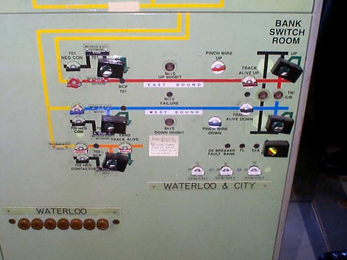
The Electric Control Room at Raynes Park presently controls traction power to the Waterloo & City. This view shows the small part of the large mimic diagram relating to the Waterloo & City.

At present, traction power is still provided from the Network Rail Main Line Traction Substation via d.c. track feeder cables. There are two tunnel traction sections, one for the Down or Westbound line (section 700), one for the Up or Eastbound line (section 701) line. The Waterloo Depot area, which is not provided with tunnel telephones, forms a third traction section (section 702). Traction sections are fed via high-speed d.c. circuit breakers, similar to London Underground standard practice. At the remote end of the Up and Down lines, Bank, a Track Paralleling Hut was provided to minimise voltage drop. However, this feature was never commissioned and the railway operates as two single-end fed traction sections.

A new Traction Substation is being completed within Waterloo station near the Waterloo & City line and, once this is commissioned, the Network Rail Main Line Traction Substation will no longer be involved in the operation of the Waterloo & City line.

In 1989 Network South East, who were by then responsible for the line, ordered replacement rolling stock of the LUL Central Line pattern, providing five 4-car sets. Cranes were needed to remove the old rolling stock and deliver the new trains to the depot area, since the Armstrong Lift had been removed as mentioned above. Some civil works were needed to accommodate the new stock and the current collection system was changed from third rail to standard London Underground fourth rail pattern in 1992.


Present Waterloo & City vehicle.

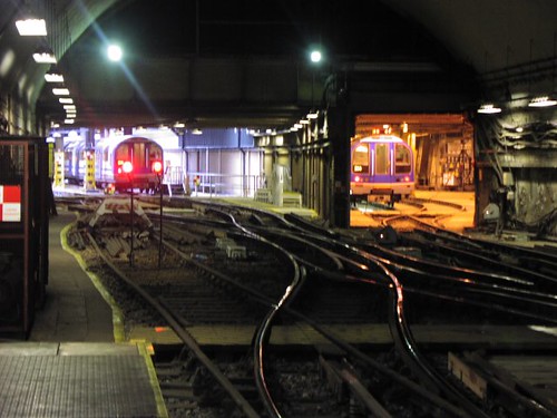
The depot at Waterloo, viewed from the Arrival platform, in 2004.

Westinghouse replaced the old signalling system in 1992 with a relay interlocking controlled from an 'NX' mosaic panel.

The 'NX' signalling control panel at Waterloo in 2004.

Around 2007, a new Service Control Centre was constructed within Waterloo station. This was provided with a solid-state signalling interlocking system controlled from workstations. The 1992 Westinghouse signal box has been retained as an Emergency Service Control Centre.

The present Service Control Centre at Waterloo.

Related information on other websites

Clive's UndergrounD Line Guides form an excellent reference to all of London Underground. The Guide for the Waterloo and City line is here.

There's a Wikipedia article here.

Related posts on this website

All my posts on London Underground can be found here.

Books

In my introductory post London Underground and Jan, there's a list of books about London Underground. From this list, these two are of particular relevance to the Waterloo and City Line:-
[ 1] 'The Waterloo & City Railway' (a very detailed history running to over 460 pages).
[ 2] ‘Railways of Waterloo’ (covers both the Waterloo & City and the main line station).

For a track diagram with other information, refer to another book included on the list in the introductory post here:-
[13] 'Railway Track Diagrams Book 5: Southern and TfL' Third Edition, published by TRACKmaps (ISBN 978-0-9549866-4-3).
Pictures

Waterloo & City.

[Flickr ref updated 3-May-2020]

Tuesday, 6 October 2015

London Underground and Jan


(Click on map for larger view)
London Underground Map 2015 (Transport for London).


When I was quite young, I was introduced to the London Underground on a visit to London with my parents. I think I was terrified and fascinated in equal parts. Terrified by the speed, the noise and descending into the bowels of the earth to board the trains - fascinated by the frequency of trains and the relative ease of moving underground around London. As an adult, I was happy to utilise the tube but it never had the attraction of steam railways. Even after my firm started supplying special-purpose telephone equipment for railways in various countries, I saw the London Underground network merely as a means of transport, not a potential source of work.

That changed in, I think, 1995 when one of our major customers, who was bidding for a large telecommunications package in connection with the Jubilee Line Extension Project, asked us to quote for the design and supply of Tunnel Telephone equipment. Well, I had a vague idea of what was involved - most people travelling on the Tube notice the pair of bare wires carried on the tunnel wall forming part of the tunnel telephone system. These wires allow the driver to attach a portable telephone in case of emergency. None of the telephone systems we'd produced seemed adaptable to this tunnel telephone application and I thought that the costs of developing suitable equipment from scratch would make any offer we made unattractive. So we declined to quote, explaining our reason to our customer.

However, a few months later the customer came back to us, saying they'd really like us to quote, and this time we produced a quotation. Some time later (these things always seem to take an inordinate time to come to fruition - a large quotation we did for Brazil only produced an order after seven years!) we agreed a contract to design and supply the necessary tunnel telephone equipment for the Jubilee Line Extension. I then embarked on a fairly steep learning curve to better understand both the traction supply system on London Underground and the requirements for tunnel telephone systems. As we produced the necessary equipment, I became far more interested in the history and development of the London Underground system. Over the years since, I've worked on tunnel telephone systems for a number of the London Underground lines and, as time permits, I'll add more posts on this unique mass transit system.

Brief Introduction

The London Underground employs a fairly unusual fourth-rail system of electrification. I've written a little about how traction current is distributed in the post London Underground - Traction Power Distribution and there's a short background in the post Fourth Rail Electrification.

Tunnel Telephone systems used on London Underground have two functions - to discharge traction current in an emergency and allow the driver to talk to the Line Control Centre (now generally called the 'Service Control Centre'). The tunnel wires allow a driver to open the cab window and simply 'pinch' the two bare wires together (the bare tunnel wires are sometimes referred to as 'pinch wires'). This action automatically discharges the local traction section. Connecting a portable telephone to the exposed wires similarly discharges the traction section, after which a conversation with the control centre is possible. Fixed telephones with a similar function are provided at strategic locations (such as the Headwalls at stations). London Underground now call the Tunnel Telephone system the Emergency Traction Current Discharge System (ETCDS) to better-reflect its principal function. Providing speech with the control centre, in this age of Secure Cab Communication by radio, is the secondary role.


Jubilee Line: Tunnel wires mounted on cast iron tunnel lining at the junction of two adjacent Tunnel Telephone sections.

Clive's UndergrounD Line Guides form an excellent reference to all of London Underground.

For track diagrams of London Underground, refer to 'Railway Track Diagrams Book 5: Southern and TfL' Third Edition, published by TRACKmaps (ISBN 978-0-9549866-4-3).

Books

Here's a list of some of the books I've acquired dealing with London Underground:-
[ 1] 'The Waterloo & City Railway' by John C. Gillham (The Oakwood Press) ISBN 0 85361 544 6.
[ 2] ‘Railways of Waterloo’ by J. N. Faulkner (Ian Allen Publishing) ISBN 0 7110 2237 2.
[ 3] ‘London’s Local Railways’ by Alan A Jackson (David and Charles) ISBN 0-7153-7479-6.
[ 4] ‘Steam to Silver – An illustrated history of London Transport railway surface rolling stock’ by J. Graeme Bruce (London Transport) published 1970.
[ 5] ‘Inside Underground Railways’ by Alan A. Jackson (Ian Allen Ltd.) published 1964.
[ 6] ‘The London Underground – A diagrammatic history’ by Douglas Rose (Douglas Rose) 3rd edition ISBN 0 9507101 5 6.
[ 7] ‘Underground Train Overhaul – The Story of Acton Works’ by J. Graeme Bruce/Piers Connor (Capital Transport Publishing) ISBN 1 85414 134 1.
[ 8] ‘The Northern Line – An illustrated history’ by Mike Horne/Bob Bayman (Capital Transport Publishing) 2nd edition 1999 ISBN 1 85414 208 9.
[ 9] ‘The Story of London’s Underground’ (London Transport) revised edition 1966.
[10] ‘British Electric Trains’ by H. W. A. Linecar (Ian Allen) 2nd edition 1949.
[11] ‘Handling London’s Underground Traffic’ by J. P. Thomas (London Underground) published 1928.
[12] ‘The London Underground Tube Stock’ by J. Graeme Bruce (Ian Allen Ltd.) ISBN 0 7110 1707 7.
[13] 'Railway Track Diagrams Book 5: Southern and TfL' Third Edition, published by TRACKmaps (ISBN 978-0-9549866-4-3).
[14] ‘London Underground Guide 2015’ by Jason Cross (Train Crazy Publishing 2015) ISBN 978-1-907648-10-6.
Related posts on this website

All my posts on London Underground can be found here.

My pictures

My coverage of London Underground lines is very patchy and quality is generally rather poor, I'm afraid. All these albums are shown here.

[Book {14} added to book list 11-Apr-2021]

Thursday, 7 May 2009

Fourth Rail Electrification

Fourth rail electrification, White City, London Underground

Electric railways were introduced towards the end of the 19th century. Electric traction was particularly suitable for use on underground railways where steam traction could be particularly troublesome. Early systems used locally-generated direct current, produced by stationary steam engines.

Largely because of the available materials for generators and motors, working voltages were limited to six or seven hundred volts. At these relatively low voltages, currents are fairly high, so a third rail, the conductor rail, was provided to carry the traction current between the feed point and the train to be powered. One or both running rails were used to return the current to the feed point. The conductor rail was carried on glazed porcelain insulators (invariably called 'pots') mounted on the transverse timbers ('sleepers') to which the running rails were also fixed. The high insulation resistance of the insulators ensured that almost all the current flowing in the conductor rail was that drawn by the train.

The situation was more complex as far as the return current from the train was concerned. The running rails were held at the proper gauge by fixing them rigidly to the sleepers which, in early days, were generally made of wood - a reasonable electrical insulator. To provide resilience against the dynamic loads of passing trains, the sleepers were buried in ballast, often crushed limestone - again a reasonable insulator. Sleepers and ballast were in contact with the mass of the earth. The earth resistance from the running rails may be fairly high in dry conditions but, when wet, earth resistance falls. Although most of the return current would flow from the train to the feed point through the rail, a proportion leaked from rail to sleeper and from sleeper to ballast so that a significant current flowed through the mass of the earth. If there were nearby metallic water or gas pipes, some of this stray current could flow through them, causing damage by electrolytic action.

The situation was even worse in deep tube lines, which were lined with sectional cast iron sections which would not only suffer electrolytic action but, if rings were not bonded together, could display arcing. To mitigate this problem, London's Underground evolved with a 'fourth rail' to carry the return current via a path isolated from earth.

The outer conductor rail is positive at around +420 volts and the inner conductor rail, mounted between the running rails, is negative at around -210 volts. These are the theoretical voltages under dry conditions. Leakage resistance across every porcelain insulator will provide a multitude of paths to earth from both conductor rails which can alter the voltage to earth ratio of the positive and negative conductor rails. To define the 'normal' ratio, London Underground provide bleed resistors every so often connected from each conductor rail to earth. This 'normal' ratio will be subject to significant change on surface lines under varying weather conditions.

Fourth rail electrification with modern concrete slab track

For notes on traction power distribution on London Underground click here.

For an excellent article on conductor rail systems by Russ Elliot click here.

The world's railways use a wide variety of d.c. and a.c. electrification systems employing both conductor rails and overhead conductor systems - to see the Wikipedia article on 'Railway Electrification' click here.

Related posts on this website

All my posts on London Underground can be found here.

Wednesday, 11 February 2009

London Underground - Traction Power Distribution

White City, pictured during an Engineering Possession.

These notes on London's Underground Railways are taken from training material prepared by Ford Electronics Limited, with permission. Ford Electronics produce Tunnel Telephone systems for use on underground railways. This description applies to most lines, but there are local differences.

Introduction

London Underground uses d.c. traction power distribution from a series of substations at the relatively low voltage of around 630 volts. The conductor system consists of conductor rails laid along the track route allowing power to be picked up continuously by the train through its shoegear equipment. The positive conductor rail laid outside the running rails and the negative conductor rail laid between the running rails are supported on porcelain insulators at a maximum pitch of around 4.3 metres.

At turnouts, crossings, expansion gaps, isolator switches and section gaps the conductor rails are broken. Ramps at the start and end of conductor rail section lift the train collector shoes onto the rail or lower the shoes from the rail. The length of the gap depends upon the track feature. At turnouts and crossings, the gap is variable. Expansion gaps are normally 1 metre, provided every 246 metres on the surface and every 606 metres underground. Isolator switch gaps are normally 1 metre and Section gaps 15 metres.

The outer conductor rail is normally about 450 volts positive with respect to earth and the inner conductor rail in between the running rails is normally about 180 volts negative with respect to earth. The d.c. power is not directly earthed and the actual voltage to earth on each conductor rail will depend upon the insulation resistance. During wet weather on exposed lines, around 300 volts on each conductor rail is possible. Intentional indirect earthing through Bleed Resistors (see below) is provided at certain locations to establish the conductor rail to earth voltages during non-leaky conditions.

Source of traction power

Originally, London Underground produced its own power at generating stations like Lots Road, which no longer exists. Nowadays, power is taken from the National Grid at a number of sites at either 11kV or 22kV 50Hz, but London Underground currently retains the capability to generate power at a peak-lopping gas turbine installation at Greenwich, which is only used as emergency supply if the grid fails. As necessary, this high voltage a.c. power is distributed to Traction Sub Stations. To provide the necessary supply security Traction Sub Stations frequently have alternative sources, usually at 11kV 50Hz.

Traction Sub Stations

Transmission losses at 630 volts d.c. are relatively high so, to avoid excessive voltage drop, Traction Sub Stations (TSSs) have to be located quite close together. Originally, Traction Sub Stations were staffed but they are now remotely controlled from a power control room at a central London site.

At each Traction Sub Station, the incoming three-phase high voltage supply is transformed down and rectified (using fan-cooled semiconductor rectifiers) to provide the earth-free d.c. supply for the conductor rails. A typical rating for a single rectifier unit is 1500kW. Substations are normally provided with two or more rectifiers. Often, one rectifier will power the two roads in one direction, a second will power the two roads in the other direction. Circuit breakers allow individual roads to be discharged.

The conductor rails are divided into sections extending from one Traction Sub Station to the next. Each section is double-end fed with d.c. from rectifiers at both Traction Sub Stations, to further minimise voltage drop, particularly when more than one train is in a section. A simplified diagram of the arrangement is shown in Figure 2.1 below.

The practical arrangement of a typical Traction Sub Station with two rectifiers is illustrated in Figure 2.2 below.

The substation has two d.c. busbars linked or isolated by a coupling breaker. Each rectifier and each road supplied is associated with a circuit breaker. At most TSSs, the coupling breaker is normally closed so that both rectifiers and all four roads are connected together to minimise voltage drop.

Track Paralleling Huts

At Track Paralleling Huts, the conductor rails are broken to form a section gap, but normally contactors are closed to connect together all the positive conductor rails and all the negative conductor rails. Again, the aim is to reduce the voltage drop as a number of rectifiers can contribute current to each section. The arrangement is shown in Figure 2.3 below.

Sectionalisation

As described above, at most Traction Sub Stations the coupling breaker is normally closed so that the conductor rails are effectively continuous from section to section. Since the conductor rails are not directly earthed, an earth fault from one side of the supply to earth (for instance, on a traction motor or collector shoes) does not prevent the system from operating. But a second earth fault on the other side of the supply will cause the overcurrent protection to operate. If all the coupling breakers were closed, a second earth fault could propagate a shutdown along the whole length of the line, involving a large number of passengers.

To limit this fault propagation, London Underground introduced a technique called 'Sectionalisation' where a number of traction sections are connected together (to help minimise voltage drop) but the coupling breakers are intentionally open at the Traction Sub Stations defining the ends of that Sectionalisation section.

Bleed Resistors

In the absence of leakage currents to earth from the conductor rails, the voltage of each conductor rail with respect to earth is defined by a potential divider of bleed resistors added at each end of the Sectionalisation Section from each conductor rail to earth. The conventional values are 220 ohms (positive rail) and 110 ohms (negative rail).

Related articles in this Blog

Fourth Rail Electrification

Tunnel Telephone System

In tunnel sections of the system, a Tunnel Telephone system is provided to facilitate traction discharge and voice communication between the driver and Line Controller. Traction trip and speech is provided over two bare copper alloy wires carried, one above the other, on pairs of porcelain insulators supported on metal brackets fixed to the tunnel wall, usually on the right-hand side in the normal direction of travel. The insulators are generally provided every 6 metres along the tunnel so as to keep the wires about 115mm apart. The wires are positioned so as to be accessible by leaning from the driving cab window of a train. The general appearance of a single-bore deep tunnel is shown in Figure 2.4 below.

Where it is necessary for the tunnel wires to be carried across to the opposite tunnel wall, Over Track Crossings (OTX) are provided using cable. Where different sections of tunnel wire need to be interconnected, or equipment introduced, cabling is used and test boxes with sliding disconnection links may be provided to facilitate fault-finding.

Related posts on this website

All my posts on London Underground can be found here.

This topic is continued at London Underground - Traction Power Distribution (2).

[Bleed resistor values transposed, link to part (2) added 11-Apr-2021]