Friday 20 January 2012

Review of the Year - 2011

I'm pleased to be able to say that 2011 was another good year for me and I'll mention some of the highlights below. I'm still working at Ford Electronics where most of our projects are railway-related but, for commercial reasons, I don't normally put much in the blog about this important area of my life. The year wasn't all good, of course, but let's emphasise the good bits. I've divided the review into 'OVERSEAS TRAVEL', 'RAILWAYS' and 'BREWOOD HALL'.

OVERSEAS TRAVEL

There were three overseas trips in the year, all very enjoyable and instructive.

Saint Helena and Ascension

I was determined to visit the island of Saint Helena in the South Atlantic before they build the long-threatened airport, which will surely transform island life for ever. The picture shows Jamestown, St. Helena, viewed from the sea. After a few days on the fascinating island, I then sailed on to Ascension Island where there is an airport but the only flights are RAF Transport Command! This trip exceeded my expectations and you can find the various posts on the trip here.

Russia

On the second trip, I flew to Moscow and joined one of the many river ships which cruise between Moscow and Saint Petersburg on a combination rivers and canals. There were some fascinating contrasts as we moved between cities, towns and villages. The picture shows the improbable-looking, wood-constructed Transubstantiation Cathedral on Kizhi Island.My reports are here.

Burma

For my last overseas trip in 2011, I returned to the river cruise ship 'Road to Mandalay' in Burma. I re-visited two schools, visited three schools for the first time and visited two boys' and one girls' orphanage. At each place, I helped in the distribution of charitable support provided through 'Road to Manadalay' by the ship's passengers. I also participated in the official opening of a new Medical Clinic in Bagan built, staffed and supported by the 'Road to Mandalay' and its passengers. The picture shows a group of brick pagodas in Bagan. My reports on the trip are here.

RAILWAYS

During the year, I continued driving at Peak Rail, the Battlefield Line and the Museum of Science and Industry in Manchester on a regular basis. I'm still secretary of the Old Locomotive Committee (LION's supporters club). I'm also involved with an informal Historical Group researching railways in the West Midlands. In March 2011, the Historical Group held another Slideshow and Meeting at Brewood. For the rest of the year, communication was mainly by a (sometimes frantic) exchange of e-mails. In connection with that research, there are a number of articles in the blog about Traffic Movements and signal boxes in the '60s. I've also put rough sketches of a number of track diagrams in the blog (before I lose them again).

Old Locomotive Committee

The A.G.M. in May 2011 gave members a last chance to view 'Lion' before her transfer to the new Museum of Liverpool (see below).

Agecroft No. 1

In June 2011, I had my first opportunity to drive newly-restored Agecroft No. 1. She's proved a popular and reliable performer and made many new friends on her visit to the Tanfield Railway.

Day out with Thomas

At the Battlefield Line Day out with Thomas, I shared the driving on 'Thomas' with Eddie on the 25th June 2011 and returned the following day to drive 'Daisy', the 2-car DMU.

Matlock Station Re-opening

The first Peak Rail trains into the former down platform at Matlock station ran on Friday 1st July 2011, reserved for invited guests and Peak Rail shareholders. The first revenue trains were on Saturday 2nd July 2011, when I drove 68103 as part of the Matlock Station Festival Reopening.

Lion Shoot

On 6th July 2011, John Hawley and I took part in the Lion Shoot, where Centre Screen filmed interviews to be incorporated in the Audio-Visual interpretation of 'Lion' in the Museum of Liverpool (see below).

Lionsmeet

Lionsmeet 2011 was held at Chelmsford on 30th July 2011. After a good contest, the Mike Parrot Memorial Cup was won by Jon Swindlehurst.

Summer Saturday at Shackerstone

On 27th August 2011, I had my first turn on the Great Western 2-8-0 currently at the Battlefield Line. More details here.

Thomas visits MOSI

Thomas made his second visit to the Museum of Science and Industry in Manchester in September and I was driver on 1st September 2011. More details here.

Thomas visits the Battlefield Line

'Thomas' was back at the Battlefield Line in October for two weekends. On the 9th October 2011, I was driving 'Daisy' the DMU and on the 16th October I was in charge of 'Thomas'. More details here.

Royal Opening of the Museum of Liverpool

I was present at the Official Opening of the Museum of Liverpool by Her Majesty the Queen on 1st December 2011. There's a report here.

Peak Rail Santa Specials

Peak Rail had another well-patronised 'Santa' season. I was the driver on 10th December 2011 on visiting locomotive 'Sapper'. My report is here.

Battlefield Line Santa Specials

The Battlefield Line Santa Specials were handled by popular visitor '3803'. I was the driver on 17th December and had a great time.

MOSI Christmas Trains

Agecroft No. 1 handled the MOSI Christmas Trains and I was driver on 29th December. The weather was pretty bad but we still had lots of passengers (the photograph above was taken earlier in the year).

The 'Mince Pie Flyer'

On New Year's Eve, I drove the recently-outshopped single-unit DMU ('Bubble Car') on the Mince Pie Flyer at the Battlefield Line. The weather was pretty good and plenty of passengers turned up. An enjoyable end to the year!

BREWOOD HALL

No major works in 2011, just ongoing maintenance. Various visits from friends and family, plus three Group Visits outlined below.

Wulfrun College Retired Staff Association

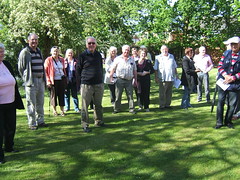
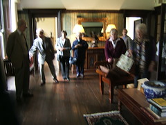
On 23rd February the Wulfrun College Retired Staff Association visited Brewood Hall. There's a very brief report here.

'History Walks'

A party of 41 from History Walks toured Brewood Hall on 8th May.

National Association of Decorative and Fine Arts Societies

NADFAS visited on 13th October and there's a report here.

EARLIER REVIEWS

2010
2009
2008
2007
2006

Wednesday 18 January 2012

Peak Rail in Winter

'Sapper' in the frost: Up train approaching Darley Dale. Click above for complete image.(Photo: Sheila Rayson)

Peak Rail tries to operate a passenger service all the year round but in winter it's restricted to Sundays. I was rostered as Driver on Sunday 15th January 2012, with Dave as Fireman. As I walked across the yard at Rowsley to the outside pit at the shed, I noticed that our train had been reduced to 5 coaches (we'd run with 7 on the Santa Specials). This wasn't surprising - the Santa trains usually run at peak loading (no pun intended) but the shorter train should be adequate to meet the demand on a cold January Sunday. As far as I knew, we were top-and-tail to Matlock (Town), as all the services have been since we re-opened Matlock Station, apart from the Santa Specials. I also wasn't surprised that there was no big diesel attached to the north end of the stock yet - the first passenger departure was not until 11:15. But I was surprised that the tank wagon parked opposite the south end of the stock used to replenish the locomotive water had been removed as this would make watering during the day harder.

Dave had signed on at 04:00 to 'light-up' so, by the time I arrived a little before 07:00, matters were well in hand and Austerity tank locomotive 'Sapper' was radiating warmth (although there were still four-inch icicles hanging from the underframe). It was still dark and the thermometer was down to minus five Celsius as I started oiling round. I'd no time to feel sorry for myself as we were due 'off shed' at 08:15, light engine to Darley Dale to pick up our candidate for a two-hour driving experience course. I've described the preparation of this class of engine here.

We were ready on time and, in possession of the single line staff for the Rowsley-Church Lane section, attempted to move away. Something was frozen but, after a slight pause, things freed themselves and we moved off. The hand points we had to change were stiff with frost and the ground frame which let us onto the running line was heavy to operate. We gently ran down to Church Lane Crossing where Rob let us through the gates and we surrendered the staff. I commented to Rob about the missing water tank to be told there was no diesel that day. "So we're on our own?" I exclaimed as the consequences sank in. If we were on our own, it would be like the 'old days' when we ran round the train each end and did all the work ourselves. Our destination would be Matlock (Riverside), where there are run-round facilities, rather than Matlock (Town). But, at least, we'd be able to water at the grey tank wagon at Rowsley as we ran round (provided it wasn't frozen!). Dave and I looked at one another - normally we'd both relish the extra work, but we'd turned up expecting a fairly easy shift and that had now changed. Oh well, "Embrace the Unexpected" is one of my sayings.

We continued to Darley Dale Up Platform and met up with our trainee driver, just as the Station Staff were arriving. By this time, Rob had driven by road from Church Lane to Darley Dale so that he could let us through the Darley Dale Level Crossing. Once introductions were made and our trainee was on board, Rob let us over the Crossing and gave us the single line staff for the Darley Dale-Matlock section. Our trainee was a good driver, although he'd never driven a steam locomotive before, so we had a pleasant but rather cold couple of hours pottering between Darley Dale and Matlock Riverside. I've described the format of the Peak Rail driving experience courses here.

With the current timetable, driver training is 08:45 to 10:45 then we're booked light engine back to Rowsley, ready for the first passenger train at 11:15. We said goodbye to our trainee in the Down platform at Darley Dale and Jackie called across that we'd be taking a film crew from Darley Dale on our first Up train. We hadn't time to find out more as we needed to water at Rowsley before 'tie-ing on' to our train. With the passenger coaches stabled in the platform at Rowsley, we had to go around the loop to get to the grey water tank (which, to our relief, was not frozen), take water and then return via the loop to get to the south end of our train. By the time we'd done this, we'd only a few minutes to start steam heating the coaches before the first passengers boarded - not long enough. I've talked about 'hooking on' to a train and steam heating in On the Footplate Part 2. Because of the heavy frost, I also wanted to be sure I'd done a 'functional' brake test on the vacuum brakes, checking that brakes could be applied along the train by the driver. If brake cylinders become frozen in the released position, the driver may discover he has a lot less braking effort than he expected! There's more about the vacuum brake in Section 4 of the article Brakes. A proper test involves a lot of walking up and down alongside the train, first checking that the brakes can be applied and then checking that they can be released.

I didn't make a note of our departure time by the time the station staff were ready to send us out. We were late and, I knew, destined to become later when we picked up the film crew. We had a gentle run down to Church Lane where we were checked by the signal whilst the signalman manually pushed the gates across. During the day, we were checked or even stopped each time we passed Church Lane. On one Up train, we were called on by a yellow flag so we approached the facing motor points very cautiously, to ensure they were correctly fitting-up, before we moved across them.

We arrived at Darley Dale and were introduced to James Lewis, an auctioneer and valuer well-known for his appearances on various television antiques programmes. He was already dressed in a boiler suit and was to travel with us on the footplate to Matlock and back with his cameraman. James proved to be good company and he was very enthusiastic about accompanying us. The footplate on an 'Austerity' tank is not that large so, with Driver, Fireman, Cameraman (porting a large, professional camera) and James aboard, I remember at one point saying "One of us is going to have to go on a diet!". Eventually, they had recorded the shots they wanted (and the third member of the film crew, the Director, had taken a footplate ride) so we said goodbye to our visitors.

James Lewis saying goodbye after his footplate experience. (Photo: Sheila Rayson)

Now about twenty minutes late, we carried on with the timetable. With the various temporary speed restrictions, there's not much scope for catching up lost time 'on the road'. It has to be done by smart running round or watering, leaving little opportunity for getting food or drink. At about 13:30, Dave was relieved by Phil as fireman. As the heading picture shows, the scenery looked very attractive with the heavy frost but, boy, was it cold. We normally try to avoid black smoke but, on an afternoon Up departure from Darley Dale, Sheila asked for a bit of an effort and you can judge the result (below) for yourself. In warm weather, of course, steam can remain invisible but cold air condenses steam to water vapour, giving quite impressive results.

'Sapper' takes an Up train out of Darly Dale. (Photo: Sheila Rayson)

For the last round trip from Rowsley, we lit the locomotive lamps. There's an article on lamps here. By the time we arrived back, it was quite dark but we were on time. We 'hooked off' and made our way back to the shed's outside pit, about nine hours after I left it that morning. The method of disposal currently in use at Peak Rail is a little different from that described in the article Disposal, but the principles and the hazards are the same. I partially filled the boiler but left '100 pounds' (100 pounds per square inch) on the 'clock' so as to be able to make the final movement into the shed with an effective steam brake. By closing right up to the diesel shunter in the shed, we were 'inside, clear' and Phil was able to close the roller shutter door whilst I finished filling the boiler. As Phil and I had a wash (it's difficult to keep clean on a steam locomotive but I have worked with people who manage it) we agreed that we were both fairly exhausted but had had a good time.

There are detail pictures of 'Sapper' here.

A number of articles about working on locomotives are linked above. You can find all of them here.

Friday 13 January 2012

The Titfield Thunderbolt

The well-known poster for the film by Edward Bawden.

All of the 'Ealing Comedies' series of films are well-known and well-loved. But 'The Titfield Thunderbolt', released in colour in 1953, is surely one of the most affectionately remembered. This is partly because of the use of a genuinely old locomotive called 'Lion' which, for the benefit of the film, was renamed 'The Titfield Thunderbolt' and turned out in a fairly striking livery.

In the 1950s, I think I saw the film four times in the cinema so, even at that tender age, perhaps my later association with railway preservation could have been predicted. In fact, it was not until I was in my mid-40s that I actually got involved in preservation, first becoming a member of 'Lion's' Supporters Club, the Old Locomotive Committee (OLCO) and later becoming involved with a number of railways and preservation initiatives.

The film's gentle, but witty, screenplay from T.E.B. Clarke was supposedly inspired by volunteers having taken over the running of the Talyllyn Railway which, in 1951, became "The World's First Preserved Railway".

My favourite dialogue from the film comes when the Vicar declares that they must not allow the Titfield line to be closed and the Town Clerk replies that they closed the historic Canterbury and Whitstable line. With full ecclesiastical gravity, the Vicar retorts:-
"Perhaps there were not men of sufficient faith in Canterbury".

There's more about the film in an article on Wikipedia.

From time-to-time the film is still repeated on television and I'm glad to report that it's still available on DVD.

The film screenplay was adapted as a stage play by Philip Goulding and in 2005 a professional stage production of 'The Titfield Thunderbolt' toured theatres in Horncastle, Coventry, Windsor and Eastbourne. It was great fun but nothing like the film, of course. I saw the production in Coventry with the Old Locomotive Committee (OLCO) President and his wife and my review (below) first appeared in the OLCO newsletter 'Lionsheart'.

THEATRE REVIEW
by our occasional drama critic, Jan Ford

No, there's not been much call for a drama critic in OLCO. But when 'The Titfield Thunderbolt' is adapted for the theatre, we had to check it out.

How can you adapt one of the best of the Ealing Comedy Films for the stage? Well, the 'Telegraph' drama critic Charles Spencer, having seen the production at Hornchurch, commented "You can't, but you can have a lot of fun in trying". His review encouraged me to see the staging in Coventry.

It's a strange mixture of the familiar and the new. Chunks of dialogue taken straight from the screenplay, interspersed with all sorts of plotlines not in the original, yet all done with such apparent affection that it remains true to the spirit of the original.

The original John Gregson role, Squire Chesterford, is transformed into Lady Edna Chesterford, played in "jolly hockeysticks" mode by Kate O'Mara. The Reverend Weech becomes much younger, as played by Steven Pinder and the Union Representative at the Enquiry, Mr. Coggett becomes Miss Coggett. A number of these changes are predicated by the multiple roles adopted by the actors – five actors cope with fourteen roles, involving some amusing on-stage quick-changes. The sheer gusto and good nature of the cast soon dispels any thoughts of wobbly sets or improbable plotting.

The short season (Hornchurch, Coventry, Windsor and Eastbourne) is now finished but, if there is another season, and I certainly hope that there will be, I strongly recommend that you check it out for yourselves.

The cover of the Programme for the 2005 production in Coventry of 'The Titfield Thunderbolt' starring Kate O'Mara and Steven Pinder.

I believe the stage play has since become a popular choice with dramatic societies. At the time of writing, I've just learnt that Southport Dramatic Club have a production running from 27th January 2012 to 4th February 2012 and I'm delighted to copy their playbill below:-

There are a number of articles in my blog about the locomotive that starred as 'The Titfield Thunderbolt' and the locomotive's "Supporters' Club", OLCO. You can find them here.

Driving 'Lion'

'Lion' (minus its tender) being prepared for display in the Museum of Liverpool. The whistle is visible at the top, with its steam cock handle. The regulator handle is at 10 o'clock - the fully open position. The reverser can just be seen on the right of the firebox.

It's over twenty years since 'Lion' steamed but, before that, I had a few opportunities to actually drive 'Lion'. A correspondent asked whether driving 'Lion' was very different from driving 'Modern' locomotives. The answer is "not very". The basic principles of the steam locomotive haven't changed a great deal since the early days but, clearly, all sorts of refinements have been attempted (with varying degrees of success) over the years.

To move a steam locomotive, the driver has to decide which way he wants to move, forwards or backwards, and set the reverser (a lever in 'Lion') accordingly. The driver has to ensure that the hand brake is released (the hand brake will become important when it's time to stop). The driver will then open a steam valve to allow steam to flow from the boiler to the cylinders (there are at least two cylinders, as in 'Lion', but sometimes more) to make it go.

The steam is used to push a piston from end to end of a steam-tight cylinder. The piston is attached to a piston rod which sticks out of one end of the cyclinder and it's the reciprocating motion of the piston rod which extracts useful work. Usually, that reciprocating motion is converted to rotary motion of the driving axle by connecting rods pulling and pushing either a cranked axle (as in 'Lion') or outside cranks (if the cylinders are outside the frames). The driving axle may share its turning torque with one or more other axles via horizontal Coupling Rods. 'Lion' has two coupled axles, coupled via 'Flycranks' mounted outside the outside framing and coupling rods, giving the locomotive an antique, attractive appearance which is quite hypnotic when the engine's moving.

The clever stuff is performed by various bits of moving 'old iron', collectively called the 'Valve Motion' (or 'Valve Gear'), which automatically move a Steam Valve to cut off steam to one end of the cylinder when the piston completes its travel and admit steam to the other end of the cylinder to push the piston back again. Setting the reverser alters the geometry of the Valve Motion to determine which end of the cylinder first receives steam and hence which way the engine moves. There are lots of pictures of 'Lion' and this 'old iron' here.

'Lion' is fitted with an early form of valve motion called 'Gab' which only allows the driver to select direction. Other forms of valve gear (such as the Link Motion) allow the driver to cut off steam earlier in the piston's travel for better efficiency. For instance, the '1400' tank engine shown in 'The Titfield Thunderbolt' has Link Motion controlled not from a reversing lever but from a reversing screw.

The steam whistle gives character to an engine. It's usually sounded before starting as a warning to people in the vicinity but may also be used just to express exuberance. 'Lion' has a single whistle operated by a rotary steam cock. The handle is 'parked' at 6 o'clock - moving it left or right sounds the whistle. I could manage the 'cock-a-doodle-doo' whistle commonly used on railways (called a 'crow') but "On Ikla Moor Baht 'at" requires a two-tone whistle such as provided on Great Western engines (like the '1400' mentioned above).

'Lion' has a lever (or 'pole') reverser standing waist high on the right hand side of the footplate because (in common with most early locomotives) 'Lion' is right hand drive. The Great Western stuck with right hand drive to the very end (the '1400' is right hand drive) but, because railways 'drive on the left' in England, most railways changed to left hand drive to give the driver better visibility of signals which are usually mounted on the left. There's one peculiarity on 'Lion'. Lever reversers normally stand upright when the engine is not moving (this is called 'Mid Gear') and are pushed forwards to go forwards ('Fore Gear') and pulled backwards to go backwards ('Back Gear'). All very intuitive. But, on 'Lion', you pull the reverser back to go forwards and push it forward to go backwards. This was a peculiarity of the partnership who built 'Lion' (Todd, Kitson and Laird) and continued by their successors (Kitson and Company) for a while. Whereas most lever reversers are latched in the selected position by a trigger handle a bit like an old motor car parking brake, LION's reverser has a 'T' handle where the right hand handle hinges to release or apply the latch.

The steam valve that allows the engine move is called the 'Regulator' (sometimes the 'Throttle'). It's a proportionate valve - the more you move it, the more steam flows to the cylinders. The valve itself is within the boiler (where the steam is), operated by rotating the regulator rod. The regulator on most engines (including 'Lion') is operated from a fairly long handle attached to the end of the regulator rod on the footplate to give the driver sufficient leverage to be able to adjust the valve against the pressure of steam inside the boiler. The driver moves this handle in an arc. In 'Lion', it's fully closed at about 2 o'clock and fully open at about 10 o'clock. Different classes of engine have different detailed regulator design and sweep through different arcs. For instance, most Great Western Engines move from 5 o'clock to 1 o'clock. The marvellous Great Eastern '1500' moves from 4 o'clock to 8 o'clock ('underarm'). Left hand drive engines have mirror-image regulator movements. Many L.N.E.R. engines and British Rail Standards have 'Pull-out' regulator handles moving fore-and-aft, where the handle is pulled towards the driver to open it. There's a little more about regulators (including LION'S regulator) here.

Once the train has been accelerated to the desired speed, it's usually possible to partially close the regulator and run under 'easy steam' or fully close the regulator and 'drift'. The regulator is always closed before attempting to brake.

I talk a bit about braking here. In the early days of steam locomotives, effort was concentrated on making machines powerful enough to pull a useful load and braking technology was rather neglected. The 'Lion' has no 'power brake' (usually steam-operated on later designs). There is merely a hand brake operating on the four tender wheels. Since the brake blocks of the period were wooden, this was more of a parking brake - any attempt at 'serious' braking was likely to set fire to the brake blocks!

When I worked on 'Lion' we were giving fairly short demonstration rides so braking wasn't too demanding. Having closed the regulator, we used the traditional technique developed on early railways called 'Counter-pressure braking'. That's the posh term for "shove it into opposite gear and hope it slows down". With steam cut off, selecting opposite gear causes the cylinders to act as air compressors, absorbing energy of motion and slowing the train. We'd usually combine this with judicious use of the tender hand brake to stop in exactly the right place. It's possible to enhance the counter-pressure effect by admitting a little steam - not too much or the wheels will simply spin in the wrong direction and the train will slide.

'Lion' on display at the Museum of Science & Industry in Manchester whilst the new Museum of Liverpool was under construction.

The Museum of Liverpool regard 'Lion' as one of their major exhibits and the locomotive now has pride of place in the Great Port Gallery of the new museum. 'Lion's' starring role in 'The Titfield Thunderbolt' is not forgotten and the Audio-Visual presentations interpreting the locomotive include a number of clips from the film. There's a report on 'Lion' in her new home here.

Since 1984, 'Lion' has her own supporters' club called the Old Locomotive Committee (OLCO) which forms a repository of knowledge about the history of the locomotive. 'Lionsmeet' is an annual meeting of live-steam working models of 'Lion' organised by OLCO. OLCO also has its own website here.

I've written a number of articles about 'Lion' and OLCO which you can find here.

If your interest is broader than just 'Lion', there's also a series of articles describing working on preserved railways and driving various steam locomotives. Most of these articles can be found here.

Tuesday 10 January 2012

Railway Signalling: Tipton (Part 2)

In the post Railway Signalling: Tipton I first wrote about my visits to this box.

There are track and signalling diagrams of the Stour Valley line in the 1950s in the excellent series of publications from the Signalling Record Society 'British Railways Layout Plans of the 1950's' taken from the John Swift Collection. The West Midland lines are included in 'Volume 11: LNW Lines in the West Midlands' (ISBN: 1 873228 13 9).

For details of what remained of this route in 2005, refer to 'Railway Track Diagrams' Book 4: Midlands & North West', Second Edition, published by Trackmaps (ISBN: 0-9549866-0-1). The First Edition of this book was published by Quail in 1988.

Below are some more of my recollections.

1. Tipton Station Signal Box Diagram

The best way to orient yourself in any signal box is to study the box diagram. The diagram below (from my earlier post) is rather simplified, omitting important information such as gradients (see 2 below), distances to distant signals (see 3 below), lists of spare levers and any special levers such as the level crossing gate lock (see 5 below) and details of any Block Control (see 6 below).

The diagram displayed in the box was large enough to be readily visible and hand tinted so that, for instance, stop signal arms were tinted red and distant signal arms yellow. The diagram was mounted, behind glass, in a substantial wooden frame and suspended from the roof above the block shelf. There's a simplified sketch of the block shelf showing the diagram hanging from the roof above the block instruments:-

Of course, the 'regular' signalmen would rarely give the diagram a glance since they became very familiar with every aspect of the layout. 'Relief' signalmen, who might only intermittently work the box, were more likely to look at the diagram but they often preferred to consult the 'Pull Plates', the 'badges' fixed to the front of each lever showing what other levers were first required to release a lever. But, for other visitors, the diagram was an invaluable source of information.

2. Gradient Diagrams

It's important that the signalman has a clear idea of prevailing gradients. If a train becomes divided, particularly a 'loose coupled' freight without continuous brakes, it's important that the signalman understands what may happen to any vehicles running away. Gradient profile information is included on each signal box diagram, from where this information was taken. Main and Branch lines are common between the box and the actual junction - I don't know why the two gradient diagrams show different profiles.

A sketch of the main line profile is given below.

A sketch of the branch line profile is given below, extending to Wednesbury and showing the long-gone King Street Crossing on the Tipton side of Princes End.

3. Distances to Distant Signals

Down: 759 yards and 350 yards from Home.
Up Main 35B: 876 yards from Home.
Tipton Curve: 623 yards from Home.

4. The Lever Frame and Interlocking

Tipton Station box was fitted with the a 36-lever frame. It was the earlier pattern of Webb lever frame - the L & NWR 5.5 inch centres Tumbler Interlocking Frame. For more information about L & NWR signal boxes and the fitted at Tipton Station, refer to the excellent book 'A Pictorial Record of L.N.W.R. Signalling' by Richard D. Foster, published by Oxford Publishing Company in 1982 (SBN: 86093 147 1).

I've always preferred the 'loop' catch handle used by Webb. In the 'Tumbler' design, the catch handles were not interlocked, it was the movement of the lever which moved the Hook Rack associated with the lever within the vertical Guide Rack. Actuators ('L' shaped bell cranks) transferred this movement to U-section Locking Bars moving horizontally in a Guide Rack. Full or Half Locks were attached to each Locking Bar to allow or prevent movement of the Hook Racks attached to other levers as required by the desired interlocks. The whole Locking Rack was held together by a series of vertical Backbones which held the Locking Bars and Hook Racks in position.

5. Spare and Special Levers

The box diagram listed the following Spare Levers:-
1, 8, 9, 10, 11, 12, 16, 17, 23, 24, 25, 26, 27, 28, 29, 36.

Because of the level crossing gates, there were also two brown-painted special levers. Lever 31 was the Gate Lock and Lever 32 the Gate Stops. There were no pedestrian wicket gates - a subway was provided used by both passengers to get between the Up and Down platforms and pedestrians using the public road.

Finally, there was a Ground Frame released from an Annett's Key, described in section 9 below.

6. Track Circuits and Block Control

There was one track circuit - a short 'Berth' track approaching the Up Home. The track circuit was numbered TC10013, dating from a period when track circuits were quite rare and track circuits from a large area shared a common numbering scheme. Later, as track circuits proliferated, each signal box had its own number series, starting with 'T1'. The box diagram recorded that 'TC10013 controls the Up Block Instruments. With Lever 34 (the Up Home) Normal operates the Annunciator (a buzzer reminding the signalman that a train is approaching a 'Stop' signal at 'Danger'). Line Clear Up Main requires Lever 34 Normal.'

7. The 'Fobbing Bar'

Lever 18 was painted Blue and operated a Locking or Clearance Bar. However, it was not associated with a set of facing points but was situated on the track from the Down Main to Tipton Curve Junction. This line became rising once clear of the junction with the Stour Valley and spring-operated Catch Points were provided to prevent runaway vehicles running back and obstructing either the Up Main or Down Main.

Like a normal facing point Locking Bar, the Locking Bar operated from Lever 18 usually lay below the level of the wheel flanges but was raised via point rodding from the signal box. If a train was standing or passing over the locking bar when the signalman attempted to raise it, the wheel flanges would interfere with the raising of the Locking Bar and prevent the lever movement from being completed.

Before the signalman could clear the Down Main or Up Main signals, lever 18 had to be operated both ways - this was called "Fobbing Up". If successful, the signals were released. If you'd 'pulled off' the signals in one direction, you could also clear the signals the other way without "Fobbing Up" again.

Exactly what disaster scenario this special locking was installed to prevent, I'm not quite sure. The most puzzling aspect of the interlocking was that you could "Fob Up" at any time, not just immediately before clearing the main line signals. The universal practice after a train passed on the main lines was to restore the signals to danger, wind the gates open to road traffic and immediately "Fob Up" ready for the next train, even if that train was not expected for some time. I never heard of this curious arrangement being used elsewhere, but I'd be delighted to hear from anybody with more information.

8. Short Section Working

Under normal Absolute Block Regulations, a signalman had to have the line clear for 440 yards (1/4 of a mile) beyond his first Home Signal before accepting a train from the box in the rear. This 'Clearance' was a safety margin so that, if the driver of the approaching train 'missed' the Distant and only saw the 'Red' Home Signal when he was on top of it, he'd still got at least 1/4 of a mile to make an Emergency Stop before reaching an obstruction. At Tipton, the Up Main Home was only about 350 yards before the Starting signal, so the 1/4 of a mile extended into the section of the next signal box, Watery Lane Crossing. Tipton was not allowed to accept an Up train while the Watery Lane block stood at 'Train on Line'. Similarly, Watery Lane could not accept a Down train while the Tipton block stood at 'Train on Line'.

There were old 'Face Discs' in Tipton Station box but they had been out of use for some time. What did remain was a mechanically-operated indicator for the Watery Lane Up Distant weight bar. It was in the form of a cast box fixed to the wall behind the frame with a vertical slide operated from beneath the floor. Tipton was not allowed to clear the Up Distant until the indicator showed that Watery Lane's Distant was 'Off'.

Distant Indicator at Watery Lane, as shown on Tipton Station signal box diagram.

There was a similar arrangement on the Down line and the Tipton box diagram depicted the indicator in Watery Lane box which was operated from Tipton's lever 2.

9. Ground Frame

There was a Ground Frame released from an Annett's Key, pattern 'A'. This was Roberts Siding, leading to sidings behind the Up Platform. When I was visiting Tipton, these sidings were heavily overgrown and I never saw the Ground Frame used.

The sketch above shows Roberts Siding Ground Frame as depicted in the John Swift diagram which shows the five parallel sidings behind the Up platform I remember. But his diagram also shows a second connection to sidings for "Freakley's Stone etc. Sidings" extending towards Tipton Curve. That had gone by the time I took an interest in Tipton.

10. Station Bell

The sketch of the block shelf in section 1 (above) shows a bell push marked 'BOOKING OFFICE'. This worked an electric loud-sounding bell on the adjacent station principally used to alert the station staff to approaching stopping trains. The simple bell code was:-

1 ring: Down Stopping Train approaching.
2 rings: Up Stopping Train approaching.
3 rings: Speak to Signalman on the Box-to-Box telephone circuit.

Sunday 8 January 2012

Tipton Station Shunting Frame

In other posts, I've written about Tipton Station box as I first knew it and, later, after it was modernised. In August 1965, Tipton Station box was downgraded to Tipton Station Shunting Frame when Wolverhampton Power Signal Box was commissioned. The details of the Power Signal Box commissioning were given in Special Notice 745G and the diagram below, abstracted from this Notice, shows the revised arrangements.

Signalling at Tipton Station, after Wolverhampton Power Signal Box had been commissioned.

The mechanically-worked level crossing remained and Tipton Station Shunt Frame controlled slots on the signals protecting the level crossing - WN188 on the Down and WN187 on the Up. The connections to the down sidings (and the venerable elevated ground signal mounted on the Goods Shed wall) remained mechanically operated from the Shunting Frame but an electrical release was first required from the Power Box.

The earlier illuminated track diagram was replaced by another, showing the revised arrangements. The new diagram was supplied by Westinghouse who were the main contractors for the West Midlands power box schemes. The block signalling equipment was taken away and the approach of trains was indicated on Train Describers. These were crossbar-switch equipment supplied by Standard Telephones and Cables.

A sketch shows the new illuminated track diagram:-

Sketch of illuminated diagram in Tipton Station Shunt Frame (after Birmingham New Street Power Signal Box had also been commissioned).

I worked the box as a Shunting Frame a number of times but a lot of the interest had gone. There are more details here.

Further changes lay ahead. The Down Sidings were taken out of use, the gates were replaced by four lifting barriers with skirts. Tipton Station Shunting Frame was finally closed when Closed Circuit Television was installed and the level crossing was remotely monitored from Watery Lane Crossing. Eventually, the long-promised underpass was constructed and Tipton Owen Street now dives under the railway. There is now very little evidence of how things used to be, apart from the passenger station itself.

Friday 6 January 2012

Traffic Movements at Tipton Station Box (1965?)

I've been unable to date this period of observation so far but the reference to the Colour Light implies it's after Tipton Station box was modernised. It's probably early 1965 and very likely a Saturday afternoon. No Train Register entries have been found.

(1) The Up '1-4' has 13 minutes before the Up Express so we take him on.
(2) The Down 2-3-1 ('Out-of-Gauge Load') is slipped onto the Curve, causing us to refuse the Up '4' for a moment, whilst the freight clears the junction.
(3) The Colour light goes to 'No Light'. Bloomfield stops the Express, so we cancel the train forward to Watery Lane. Then the 'phone comes back so we get the Express away.
(4) Watery Lane won't have the '1-4' now waiting at our Up Branch Home so a '4' runs next on the Up.
(5) Finally, we get the road for the Up Freight - 76042 with ballast in 'CATFISH' wagons.
(6) Open the gates to road traffic after the Up Ballast. Immediately receive 'Section' for the Down train. Close the gates to road traffic and pull off. He runs by with the engine whistling furiously.
(7) We take on a '4-1' from Princes End.
(8) Simon (S&T Lineman) gets the Colour Light back on. Are we back to normal? I wonder?
(9) The '4-1' is only short so we send him on to Watery Lane. He stops to shunt at Watery Lane.
(10) The Down Local picks up his passengers at Tipton without incident.
(11) Simon has an explanation for the Colour Light failure (not recorded what it was!).
(12) Next, 5288 comes off the Branch with a second trip - steel bars loaded on BBEs.
(13) A Fowler '4F' passes on the Up and backs inside with his brake at Watery Lane. He's to pick up at Watery Lane, after the Up Local has gone.
(14) On the Down, 8335 tender-first arrives with 12 Engineer's wagons and 15 Tiptons - steel mainly. He puts off the Tiptons on the front road, backs up and disappears towards Spring Vale.

Thursday 5 January 2012

Traffic Movements at Tipton Station box, 1965

There's an introduction to Tipton Station box as it was when I first knew it here.
There's a more detailed description of the modernised box in preparation.
There's a description of the box after demoting to a Shunting Frame here .

On Saturday 10th July 1965 I started the day at Tipton Curve Junction (traffic movements described here) and moved on to Tipton Station Box later in the morning. It was a rather difficult time for the signalling staff in the area since redundancy notices had been issued in connection with the commissioning of Wolverhampton Power Box, scheduled for August 1965.

Tipton Station box, Saturday 10th July 1965

Externally, the signal box was largely unchanged but inside it had received all the modern electrical safety refinements: continuous Track Circuiting, Illuminated Diagram and full Block Control with 'Welwyn' releases. This was only to last until August 1965, when the box was demoted to a 'Shunting Frame' following the commissioning of Wolverhampton Power Box.

As we arrive at 10:48 (the 24-hour clock was introduced with the summer timetables), the '4-1' from Princes End comes to a stand at our branch Home Signal. After the Up express, we run the freight off the branch and a light engine for Albion follows from Princes End. He passes at 11:03, a Class 8 (perhaps to work the Albion Tanks?).

Then weird things start to happen:-
1) The signal light repeater buzzes but, when we check, it's a 'spare' position causing the fault.
2) The Up colour light Distant 35a buzzes - the signal reports having gone to 'Standby'.
3) The Up Inner Distant Repeater 35 b/c goes to 'Wrong'.
Nobody knows what's going on.

On the Down we 'take on' 1S61 at 11:30 but when we try to offer the train forward, we discover that all bell and block communication with Bloomfield Junction has been severed! At least the 'phone still works, so 1S61 goes down 'on the phone', no block under Regulation 25 a (iii).

First the signal light repeater is restored, then the block comes back, then the colour light goes back to 'Normal'. That only leaves the distant repeater and that is restored in time for us to take the Up Local. We initially refuse the '1-4' offered from Princes End until the local has departed. The freight comes to a stand at our Up Branch home at 12:03. Meanwhile, the Up colour light distant fails again, restored at 12:20. We advised Bloomfield and managed to run the Up express. The Train Register shows we cancelled the express forward to Watery Lane and re-offered it. I don't know whether it was 'operator trouble' now the Up Starter is tied to the Block.

Tipton Curve opened (for just 9 minutes!) at 13:35, presumably to have a train onto or off the North Stour. Then Bloomfield Junction closed so we'd be working through to Spring Vale Sidings.

The Up Light Engine arriving at 14:58 was turned through the crossover road and despatched on the Down Branch. At this time on a Saturday, this engine would almost certainly have previously worked a train to Spring Vale and be scuttling back to Bescot for disposal.

The final entry on the Down is a Local accepted at 16:14. It amused me to 'send it on', wind the gates, pull off and then dash across to the Down platform to travel on the train back to Wolverhampton.

A copy of the Train Register entries is below:-

Wednesday 4 January 2012

Deepfields Electrical Controls

Deepfields was one of the mechanical signal boxes I got to work (unofficially) in the early 1960s. The box is described in the posts Deepfields and Deepfields in Detail

Click on image to enlarge.

In a series of articles about Spring Vale Sidings box (which was the next box to Deepfields), I discuss the electrical controls applied to this type of signal box. Part 1 and Part 2 are published, other parts are in preparation. I didn't manage to obtain prints of the electrical controls for Deepfields, but I did make rough manuscript copies which appear below. Click on any picture for a larger image.

The principles of electrical control apply everywhere so, if you're familiar with the arrangements at Spring Vale for instance, it's much easier to understand the Deepfields controls.

Drawing Symbols and Labelling Conventions

The symbols for the various circuit elements are, in general, peculiar to railway signalling. Whereas the Spring Vale drawings use the 'old' symbols, some of the Deepfields drawings use the 'simplified' symbols which are probably harder to follow, until you get used to them. The student also has to become familiar with the letter codes used to label components. As in the Spring Vale drawings, a group of letters and figures is used to identify each component. For instance, the designation '20RGCR' means [20][Red][Signal][Proving][Relay]. Once you've mastered the principal codes, understanding diagrams becomes much easier.

The Drawing Set

The set of drawings for Deepfields was numbered CW.125/59/x, where 'x' was the sheet number. These drawings were prefaced by a Contents and Ordering page. The 'Contents' gave details of the drawing pages and I'd got as far as producing a typed version of this list:-

'Ordering' was a brief stores description of the various electrical items:-

Sheet 1 Controls

This information is presented as a table comprising a row for each running line and various columns:-

Line: There is a row of entries for each running line, Up Main, Down Main and Up & Down Goods.
Block Control: Shows that the Berth Track Circuit on the Up Main controls the Block.
Line Clear: Lists the conditions which must be satisfied to be able to give a 'Line Clear'. These conditions are divided into levers in the frame which must be proved 'normal' and actual signal indications which must be proved (by electrical contact boxes attached to signal arms or weight bars for semaphore signals or 'lamp proving' for colour lights).
Annunciator: Shows that the Berth Track Circuit triggers an audible warning if a train approaches the Home Signal when 'on' and shows the time (in seconds) for which the alarm sounds before the lever lock on the home signal is released.
Track Circuits: Lists the Track Circuits associated with each running line.

A second table details the requirements for electric lever locks. A row is provided for each lever requiring a lever lock or circuit controller and various columns:-

Lever and type: Lever Locks [L] may hold the lever Normal [N] or, in the case of Facing Point Locks, Reverse [R}. Lever 1 has a circuit controller for the Green [D] relay [R] controlling Bloomfield's Down Starter. Lever 39 has a circuit controller for the Yellow [H] relay [R] controlling Deepfield's Up Starter.
Lock Proving Contacts: Lists other levers which must be proved via Lock Proving Contacts [LCC].
Track Circuits: Lists Track Circuits which must be Clear or, in the case of certain home signals, occupied before the lock is released.
Block: Lists signals controlled by the Block.
Signals: Lists signals which must be On or, in the case of the distant signal prior to the colour light, Off before the lock is released.
Replaced: Records the criteria for the colour light to be automatically replaced to danger, even when the controlling lever is still reverse.
Notes: Records that lever 1 is a control on a Bloomfield signal and that Sealed Releases are provided for the Facing Point Lock levers.

Sheet 2 Block Control Up and Down Main

Sheet 3 Block Control Up and Down Goods

Sheet 4 Lever Locks Sheet 1

Sheet 4A Lever Locks Sheet 2

Sheet 5 TPR's, TPS & Annunciator

Sheet 6 Down Main Distant and Repeating

Details of the 3-aspect colour light were not recorded, sorry.

Sheet 7 Up Starting Signal

Details of the 3-aspect colour light were not recorded, sorry.

Sheet 8 Bonding