skip to main |
skip to sidebar
On Friday, 5th November 2021, I made a brief visit to Stockport for a business meeting, travelling between Wolverhampton and Stockport using the 'CrossCountry' services in both directions via Stoke-upon-Trent. As the 2021 United Nations Climate Change Conference, also known as COP26, was taking place in Glasgow to agree how our world could be saved, bizarrely both my journeys entirely 'under the wires' featured Class 221 diesel multiple unit haulage because of non-electrified mileage at the beginning (northbound service from Reading) or end (southbound service to Southampton) of the route.
Timetables and operations have been altered because of the Covid Pandemic and I was quite surprised to see how busy services were, operated in both directions by two 4-car Class 221 coupled together
For many years I was a volunteer at Manchester's Museum of Science and Industry (there are a number of posts here), so I was a frequent traveller both by road or by train to Manchester. By train, I used the routes through either Stoke-upon-Trent or Crewe which normally called at Stockport. But, my most recent train journey to or through Stockport was some time ago so I welcomed a chance to see what had changed. Not much, it appeared. Since Avanti West Coast took over the 'Pendolino' services between London and Manchester from Virgin, they have also taken over management of Stockport station but, of course, they host the services of a number of other Train Operating Companies, including 'CrossCountry'.
I won't repeat my distaste for the 'new' (and still incomplete) Wolverhampton station. Fortunately, I didn't have long to wait on draughty platform 2 for my train. The rather modest accommodation on island platform 2/3 with simple, flat canopies remains as constructed by British Railways, albeit with some internal modernisation.
Wolverhampton Station: view from second overbridge looking towards Birmingham showing left platform 2, right platform 1. There was formerly a Middle Siding between the two tracks for which the overhead catenary remains (Blackpool by Electric Train)
I found my reserved seat (a couple who'd commandeered my seat sheepishly apologised and immediately moved elsewhere). The journey to Stockport was incident-free and on time but I'm still not a great fan of the Bombardier design. The Class 221 has 'tilting technology' to allow higher maximum speed but I understand it was taken out of use years ago to limit maintenance costs. Allowance for the six degrees of tilt either way results in the body being narrower at roof level that floor level, giving a distinctly 'narrow-bodied' feel to the passenger compartment.
Each coach has a Cummins QSK19 underfloor-mounted 6-cylinder, 6-litre turbo diesel driving an electric generator to power one traction motor on each bogie. To generate 750 h.p., the engine is run at up to 1800 r.p.m. which I find generates uncomfortable noise and vibration. Dellner autocouplers are provided.

'Cross Country' Voyager in 2010: detail of Dellner autocoupler with twin horns below.
Approaching Stockport, the appearance of the London and North Western designed signal box at Edgeley Junction Number 1 always makes me smile. In general, the route from Euston to Manchester is now commanded by a chain of modern Railway Operating Centres and Signalling Control Centres but, through Stockport, the main line is still controlled by a group of venerable signal box structures, even if now bereft of their original mechanical signalling equipment. These are Edgeley Junction No. 1 (where the line from Buxton converges), Edgeley Junction No. 2 (where the line from Chester converges), Stockport No. 1 (south end of station) and Stockport No. 2 (north end of station). Nearer Manchester, Heaton Norris Junction, a more modern brick structure retaining a mechanical frame survived for some years but has now been abolished.

Edgeley Junction No. 1 signal box.
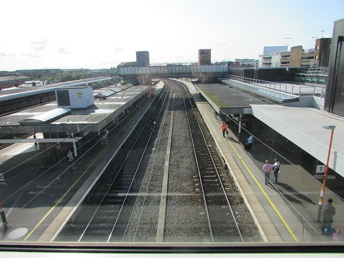
Stockport station is a strange amalgam of two very-recognisable London and North Western station buildings on island platforms 1/2 and 3/4 (internally modernised) which lead via a subway to a modern booking hall on the town side which gives access to a 'new' platform.
The 'new' platform is numbered '0' and unusual platform numbering, including the use of '0', intrigues me. There are a couple of posts here and here on the topic.

Stockport: View from platform 0 looking towards Crewe in 2013 showing two '0' platform signs (the smaller '4' sign is the stop marker for 4-coach trains).
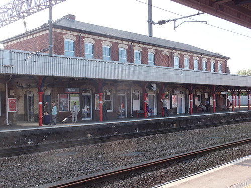
Stockport: View from platform 3 in 2013 showing the LNWR station building on platform 1/2.

Stockport: View from platform 0 looking towards Crewe in 2013 showing the LNWR station building on platform 1/2.

Stockport: View from platform 2 looking towards Manchester in 2013 showing the LNWR station building on platform 3/4.
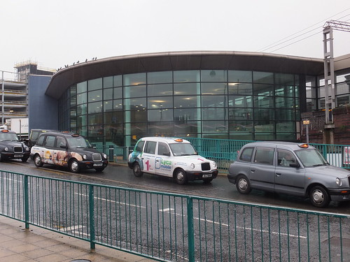
Stockport: Modern station building on Up side in 2013.
After my meeting, I returned to Stockport station with less than ten minutes to wait for a Southampton-bound 'Cross Country' which would deliver me back to Wolverhampton in around one hour. Being a Friday and late afternoon, the train was very full but I managed to find an unused seat so that wasn't too bad at all.
Related posts in this blog
The Buxton Branch.
Zen and the Art of Platform Numbering.
Platform Numbering Revisited.
My pictures
Pictures taken on earlier travels in Stockport area are here:-
Manchester Area Rail
I was rostered as DMU (Diesel Multiple Unit) driver at the Battlefield Line on Saturday, 2nd October 2021.
The 'set' comprised the Driving Motor car at the north end coupled to the Single Unit ('Bubble Car') at the south end: the customary arrangement at present. There's a second Driving Motor Car which is currently receiving attention in Shackerstone M.P.D. before being reunited with its 'other half' to form a 2-car unit. The set normally has four 150 h.p. in use, one to each bogie but one engine on the Single Unit has been using excessive engine oil for a while and the Owner recently decided to isolate that engine and run with three engines until a replacement engine could be fitted.
The thoughtful design of the 'Modernisation Series' DMUs makes it easy for a driver to safely isolate an engine which has failed in traffic, allowing the unit to 'limp home' with reduced power and this had already been done. Firstly, the Final Drive had been isolated using the hook-ended, long-handled tool stowed in the guards compartment.

Guard's compartment in 55005: The long, thin rod with a handle at the top stowed vertically in between the red-painted Brake Setter and the Guard's seat is the 'Toasting Fork' to isolate the final drive.
The 'toasting fork' allows the driver to reach over the top of the bogie, grasp the isolating switch with the hooked end and twist the switch to the 'isolated' position.
The vertical bar is the Final Drive Isolating Switch in the 'engaged' position. When horizontal, the drive is 'isolated'.
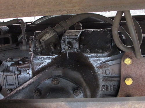
Secondly, a carriage key had been used to electrically isolate the engine, using the isolating switch on the underframe near the engine.
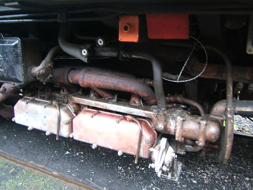
'Flat 6' DMU engine. The orange-painted square box mounted on the underframe above the engine is the switch (operated by a carriage key) to electrically isolate the engine.
It didn't take long to check oil and fuel levels, make sure auxiliary drive belts were intact and look for anything not quite right, then each engine was electrically started from the ground. Two out of three started: one refused to turn over and just made an 'Ug' sound. I started thinking about finding the battery charger and setting it up to get more life into the battery but decided to make one more attempt and this time the engine turned over sluggishly but enough to fire and we were away.
Stephen W. was booked Guard and he arrived nice and early. The day started dull and rather cold so we anticipated poor passenger numbers but when we moved the train from the DMU siding where preparation is carried out into the platform, there were quite a few passengers already waiting. We set off a few minutes late and, for a time, the weather deteriorated with intermittent heavy rain, requiring the use of the air-operated windscreen wiper. Market Bosworth had been closed to passengers during the limited operations as Covid restrictions were eased but we were scheduled to resume the intermediate stop. Whilst waiting for the Guard and Market Bosworth Station Staff to conclude station duties, I took a picture of the passenger compartment behind the driving cab.

Battlefield Line 2021: DMU on 2-Oct-2021 at Market Bosworth on the first northbound service.
We carried on to Shenton with improving weather. In fact, later in the day there was quite a pleasant sun. The dull start to the day made me anticipate poor passenger numbers but quite a few passengers turned up for each service which made the whole day very worthwhile. But I'm sure the passengers were relieved that the carriage heating was working! There are two underframe-mounted heater units on each coach. Diesel fuel (electrically ignited) is burned in a cylindrical combustion chamber and electric fans blow warmed air through ducts into the coach. The heaters are controlled from a simple panel in the Driver's cab and a switch allows fan-only operation in summer. Safety circuits are provided to ensure correct operation. The principle is similar to some warm-air portable heaters used in industry.
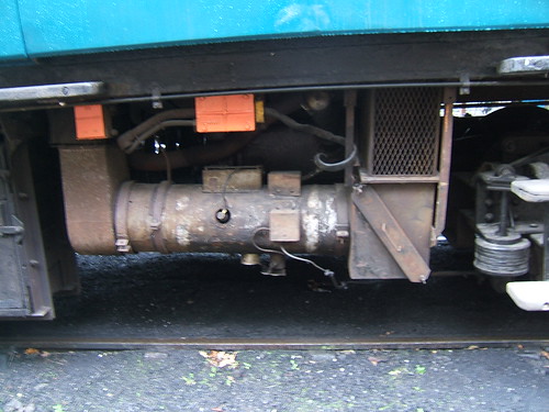 One of the two underframe-mounted heater units on each coach.
Stopping at Market Bosworth on the return trip, we picked up a large family group celebrating the birthday of one of the group. They were all staying at the Bosworth Hall Hotel in Market Bosworth and they'd decided to have a round trip on the train. The jolly crowd left us at Market Bosworth on our second north bound journey.

Battlefield Line 2021: DMU on 2-Oct-2021 showing a birthday party alighting at Market Bosworth from the second northbound service.
Our Guard had recently been passed-out to drive the DMU but had not yet had a rostered driving turn so we agreed to 'swop roles' for the third round trip so that Stephen could drive whilst Jan carried out the guard's duties.

Battlefield Line 2021: DMU on 2-Oct-2021 showing Jan completing the Guard's Journal on the third round trip.
I was back in the cab for the final round trip to Shenton then the unit was stabled in the DMU siding, final inspection made and paperwork completed after an enjoyable shift.
Related posts in this blog
All my Battlefield Line posts.
All my DMU posts.
My pictures
Battlefield Line 2021.
All my Battlefield Line pictures.
I was rostered as steam relief driver on 29th August 2021. Because of the Covid-19 Pandemic, this was the first time I'd been on a steam locomotive since August 2020 (described here). Once passenger operations at the Battlefield Line resumed in 2021, I'd been rostered on the Diesel Multiple Unit a few times but, still recovering fitness after the long period of restrictions on life, I'd not undertaken a steam turn before in 2021.
Well, rather than being just relief driver, it transpired that it would help if I covered the whole turn, which I did and thoroughly enjoyed the shift. I was helped by having Stephen W. as fireman who was both willing and capable and we both had a good day.
Previously, I'd only had two turns on 'Wightwick Hall'. The first was on 15th December 2019 (described in the latter section of the blog here). The second turn was on 28th December 2019 (described here).
The locomotive had been left outside the shed so as I hauled myself up the footsteps into the Hall's cab for the first time in 20 months, it was with a sense of excitement. A broad smile spread across my face - I felt at home. Although I knew the fireman would have already carried out the initial checks (tender hand brake applied, regulator closed, cylinder drain cocks open and gauge frame indicating satisfactory boiler water level), I repeated them. The fireman had reported no boiler leaks but a fair amount of ash and clinker on the grate from the previous day's fire. I opened the firedoors to confirm the situation.
Although the firebox was still fairly warm from the previous day, Stephen decided to go into the firebox, lift one or two firebars and push the remains of the previous fire through the opening created into the ashpan. Working in any confined space is potentially hazardous and may only be carried out with a second person on hand. The old fire was disposed, the firebars replaced and Stephen quickly left the firebox.
Preparation
The term 'Preparation' refers to the duties of both driver and fireman in getting a locomotive ready for traffic. Although driver and fireman have defined responsibilities, it's much better when the crew work as a team. I've talked about steam locomotive preparation in a number of earlier articles and a few are listed below.
Driving Turn at Peak Rail - Part One: Preparation
Preparation of Locomotive 'Sapper'
Preparing 5542 (part 1)
Preparing 5542 (part 2)
Articles with the label MIC discuss various aspects of working on steam locomotives. There's an index of these here.
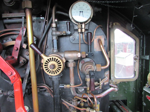
Whilst Stephen prepared to set the new fire, I began 'oiling round', starting with the sight feed lubricator mounted on the driver's side of the boiler backhead. I drained the condensate and filled the reservoir with cylinder oil (also called 'steam', 'black' or even 'thick' oil). This is a compound oil, typically with an SAE of 680 or above, which retains its properties when in contact with steam in the cylinders.
6989 'Whitwick Hall': Sight feed lubricator
Next, armed with an 'oil feeder', 'bottle' of motion oil and a 'wiper' I continued oiling the outside motion and axleboxes from ground level. It always facinates me how different trades develop their own vocabulary and locomen were no exception. The 'oil feeder', of course, is the spouted container used to dispense oil where required, called elsewhere an oil can. The 'bottle' is the tinplate oil container with carrying handle and cork retained by a short chain used to replenish the feeder as required. Motion oil is much thinner than cylinder oil, typically with an SAE of 220. The 'wiper' refers to the woven, absorbent cloth originally issued by loco stores for removing excess oil during preparation, acting as an insulating pad when handling hot objects or for general cleaning. An elderly engineman I knew asserted that a 'proper engineman' could always be identified by the wiper permanently clutched in one hand. These days, rags are often substituted for the traditional wiper.
I then transferred operations to the narrow walkway around the boiler called the foot-framing (the terms 'foot board' or 'running plate' are sometimes used), which allowed various other oiling points to be dealt with. A feature of Great Western engines is the mechanical vacuum pump, driven from one crosshead.
6989 'Wightwick Hall': Detail of crosshead-driven vacuum pump
On the 'Hall' class, there is an oil pot with a T-handled screw cap protruding through an access hole in the foot-framing on the driver's side which provides lubrication for the pump. Usually, a mix of lubricating oil and paraffin is used for this task to minimise the risk of the internal pump air valves sticking. These air valves are responsible for the distinctive 'phut-phut' noise of Great Western locomotives in motion, particularly noticeable when an engine is 'drifting' with the regulator almost closed.

6989 'Wightwick Hall': Right leading splasher showing cut-out in foot framing to give access to the vacuum pump oil pot
It's particularly important to remain alert when working on the foot-framing. Support is available from a handrail run along the length of the boiler cladding on both sides of the engine but, when kneeling to administer oil as required, it's all too easy to lose balance and it's a fair drop to the ground.
Many years ago, I learnt that lesson when getting 'Clun Castle' ready for 'Learn to be a Driver' courses at Tyseley. Now, Sam Ell's work at Swindon on draughting locomotive boilers and improving efficiency resulted in 'Clun Castle' having a double chimney and 'high superheat'. The raised steam temperatures led to the use of a mechanical lubricator mounted on the foot-framing on the fireman's side to dispense cylinder oil to cylinders, valves and regulator (rather than the normal Great Western sight feed lubricator which the original single-chimney 'Castles' retained). Mechanical lubricators are excellent but can result in oil on the foot-framing from carelessness during filling of the reservoir or vibration-induced oil line gland leakage. I didn't notice a film of oil around the lubricator, lost my balance and ended up on the floor, on my back, looking at the sky with severe pain from the near rail of the adjacent road pressing into the small of my back. I was lucky, I was able to get up and carry on with my shift (in some discomfort) but the consequences could have been serious.
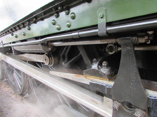
By the time I'd finished 'on top', Stephen had the fire well in hand and he offered to complete the vital oiling 'underneath'. The 2-cylinder 'Hall' has Stephenson Link motion with four eccentrics mounted on the driving axle between the frames to provide the necessary valve events to dieblocks in the expansion links. With outside cylinders and valves, as used on the 'Hall', rocking shafts are required to transmit the movement of the dieblocks between the frames (via the intermediate valve rod, rocking shaft, valve link and valve rod) to the piston valves outside the frames, as described here.
There wasn't a great deal of coal in the tender but well over 3,000 gallons of water. Stephen wasn't quite sure whether we'd complete the diagram (four round trips to Shenton) without more coal but we agreed to come 'off shed' onto our train and see how things went.
In Traffic
Unusually, we were running with a 6-coach train which meant we would 'overhang' at platforms, so I discussed with our Guard the stopping points he required to make his job easier in making sure passengers could safely board and alight.
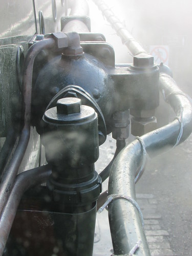
Creating vacuum to release the brakes was noticeably slower than normal. There's a post about the Great Western vacuum brake here. Both small and large ejectors are provided. Normally, I'd only use the small ejector and judge any leakage in the train braking system by the rate at which indicated vacuum climbed, but the 'little jet' alone failed to produce the necessary 25 in/Hg (inches of mercury - measure of the vacuum produced) so the 'big jet' was also needed.
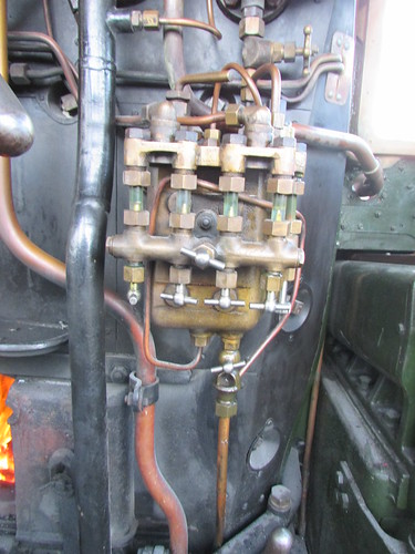
6989 'Whitwick Hall': Driver's vacuum brake application valve with radial slots to admit air, small ejector steam cock (above), large ejector steam cock (right) and blower valve (below right)
Opening either ejector steam cock admits steam to the multiple-cone ejector mounted on the driver's side of the firebox. Convergent cones in the injector body produce a jet of fast-moving steam which draws air out of the train's vacuum pipe, discharging the steam and extracted air through the pipe running horizonally along the boiler cladding to the smokebox where an elbow takes the steam/air into the smokebox to be discharged vertically through the chimney. A carefully-designed system of copper drain pipes seeks to allow condensed steam to be drained downwards but when the large ejector is first turned on, it's wise not to be near the front end of the locomotive as a shower of water may be discharged (as generations of platform-end-dwelling train-spotters learned in steam days).
6989 'Wightwick Hall': View from cab showing right side of firebox and vacuum ejector
Our first departure was booked for 11:00. I think we were a little late away waiting for passengers and then I made a gentle departure. With the cylinders cold, condensate can be anticipated in the steam circuit so the cylinder drain cocks ('taps') should be open to allow live steam to clear this condensate. Moving a train away from a platform is always the time of greatest risk when passengers may change their mind and try to get off or, perhaps worse, suddenly decide they want to get on. The Guard and Station Staff should have checked that all doors are properly closed with no handles 'cocked' (no central locking here!). Years ago, I was taught that if there are sufficient platform staff available, one should be positioned fairly near the departure end of the platform to 'chase' any door handles spotted as not properly closed. Getting under way gently is certainly desirable with 'Wightwick Hall' as she has an irritating habit of 'losing her feet' when starting and this is aggravated by the open cylinder drain cocks liberally wetting the rails ahead. Even six coaches is still a light load for a 'Hall' so, although I'd started away in full forward gear, I quickly 'wound it back' a little on the screw reverser to give an earlier 'cut-off' of live steam during each piston stroke. The fireman collected the staff from the signalman, I made sure the 'section signal' (as they now call signals admitting you to the next signalling section) was 'off' and we proceeded through the 10 m.p.h. cutting section up to Barton Lane Bridge. Once in motion, the vacuum pump will be attempting to make up losses but until speed is above 15 m.p.h., its contribution is uncertain. Normally, the small ejector will be more than enough to hold the regulation vacuum of 25 in/Hg and prevent brakes from dragging on.
A little beyond the bridge, Line Speed (25 m.p.h.) is now authorised by a cut-out '25' speed marker sign, following permanent way work and tamping of the line and this happy state now extends to the platform at Market Bosworth. Of course, that increased speed only applies when the whole of the train has passed the sign. Glancing back to check we were clear, I tugged the regulator to 'full first valve'.
Slide valve regulators have two flat valves to control the steam, both operated from a common handle. Initial movement of the regulator handle opens a smaller steam valve (called 'pilot', 'first' or 'starting') which varies the steam port size in proportion to angular regulator handle movement. At full first valve, there is resistance to further movement but a determined 'pull' will start to open a second, larger steam valve (called 'main', second or 'big') which significantly increases steam flow. Larger Great Western locomotive designs, like the 'Hall', place the two regulator flat slide valves horizontally in the smokebox, with a separate oil line from the sight feed lubricator in the cab to the regulator assembly to minimise the driver's adjustment effort as far as possible. There are a couple of articles which give an introduction to the various types of regulators in use.
Locomotive Regulators (part 1)
Locomotive Regulators (part 2)
As speed slowly increased, I wound the reverser to the recommended 'Drifting' position, marked by a stud attached to the engraved cut-off scale showing percentage cut-off.
Many valuable historical records of train performance were meticulously prepared and published by enthusiasts. When they were permitted to actually travel on the footplate, they would carefully log indicated cut-off, regulator opening (estimated by the angular position of the regulator handle against the quadrant) and frequently boiler water level/shovelfulls fired. These make fascinating reading but every old-time driver I've spoken to over the years has confirmed that few, if any, drivers took any notice of indicated cut-off, adjusting the controls until "it felt right". The indicated cut-off was not always accurate and I was told that the cut-off indicator on some Bullied engines was called "the biggest liar on the footplate".
With the light loads, low maximum speed and moderate gradients on the Battlefield Line, I've normally found that the regulator at 'full pilot' and reverser at 'drifting' will do the job and, once 'Line Speed' is achieved, the regulator can be banged closed then eased open enough to open the lubricator jockey valve to ensure oil continues to feed the pistons and valves whilst coasting. If speed starts to fall earlier than required, the regulator cab be re-opened but, depending upon the rolling resistance of the train (a combination of friction in all the wheel bearings on the train, direction and strength of any wind and any defects like dragging brakes), once Line Speed is achieved somewhere near Headley's Crossing, the train will coast to Market Bosworth, where's a speed restriction of 10 m.p.h. when any part of the train is alongside the platform. Correctly judged, this speed can be achieved by braking as the locomotive approaches the platform, performing final braking so as to stop the train in the platform. It's vital that the train is prevented from moving during this intermediate stop, either by destroying the vacuum or applying the tender hand brake. At Market Bosworth, the platform is on the driver's side, so the driver can monitor the progress of passengers getting off and on. Market Bosworth station platform will accommodate a five coach train so, with 'six on' a different stopping point was chosen, leaving half a coach off the platform each end.
Whilst waiting, I wound the reverser into full forward gear ready for starting away. The Great Western screw reverser can be a delight to adjust but I do find the one on 'Wightwick Hall' rather stiff. A long time ago I was spoilt by working on restored Castle Class 'Defiant' which had the easiest-to-adjust screw reverser of any Great Western locomotive I've worked on (together with a regulator offering genuine 'finger-tip' control, unlike the claims often made for 'balanced' or 'double-beat' types). However, my all-time award for easiest-to-adjust screw reverser goes to preserved LNWR number 1054, the Webb 'Coal Tank', where the Stephenson valve gear is adjusted by a reversing screw with a Triple-Start Thread. When I drove this lovely engine, the only problem was the absence of a handle latching mechanism, so I had to drive leaning against the handle to prevent it from self-adjusting to full gear! But that's another story.
Having received the 'Right Away' from the guard, I 'blew the brakes off', whistled, checked that the foot crossing ahead was clear and partially opened the regulator. As we moved away, I adjusted the reverser for an earlier cut-off, occasionaly looking back along the train until all coaches were clear of the platform. Leaving Market Bosworth, there's still a 15 m.p.h. speed limit over the Cattle Creep Bridge just before the turnout to Deer Park Siding so I didn't let speed rise above this until the whole train was clear of the bridge, then I set the regulator to 'full first valve' and let speed increase.
We'd been told that rain following cable laying operations between Market Bosworth and Shenton during the previous week had resulted in some displaced spoil near the running line. Although an inspection run with a diesel locomotive the previous day had passed the line as fit, some caution was advised on the first trip so I 'reined her in' as we approached the works site and we drifted through carefully, the fireman and I satisfying ourselves that all was good. Once past the works site, a little steam was needed to pick up speed then, with the reverser at 'drifting' the regulator was closed ('cracking' it to open the lubricator jockey valve) and we coasted down Shenton bank towards our destination.
The severe 5 m.p.h. speed retriction between Ambion Lane bridge and Shenton station caused by embankment slippage remains in place, so the aim was to brake sufficiently to comply with the 'slack' whilst leaving sufficient monentum to keep rolling along the platform to the 'six on' stopping point with the locomotive blocking the foot crossing.
On arrival, it's important that the Guard immediately applies the Guard's Screw Handbrake to prevent movement of the coaches whilst the engine runs round its train. I set the engine in back gear and partially released the brake so that The engine could be 'eased up', compressing the buffers between tender and coach in an attempt to slacken the screw coupling, making detaching the locomotive a bit easier for the fireman. There's a short post on coupling and uncoupling here.
The Guard collected the Single Line Staff, which he needed to work the ground frame at the north end of the run-round loop, and the Fireman walked forward to work the hand points at the south end of the run-round loop. With Driver, Fireman and Guard working together, the engine was transferred to the north end of the coaches then Stephen 'hooked-on" and set the lamps for our tender-first return to Shackerstone. Having reset the ground frame for the running line, the Guard passed the Single Line Staff back to the footplate crew, together with confirmation that 'permission to return' had been received from the Shackerstone signalman by telephone. Once all the passengers had been shepherded onto the train and the doors closed, the Guard gave the 'right away' and we gently started away.
It's a different experience running tender first with the bulk of the tender reducing the view ahead of the train. There's some view over the top of the tender on most Great Western engines (unless freshly coaled to the limit) or the driver can lean out of the cab side. When running chimney-first, leaning out usually gives a reasonable view ahead because, particularly on Great Western tender engines, the boiler is narrower than the footframing. But, tender first, the view is limited by the slab-sided tender with flared top almost the full width of the engine. There's the further complication that the tender is a separate six-wheel vehicle articulated with the engine so its exact position relative to the cab keeps altering in a rather disconcerting fashion and, on left-hand curves, the tender moves to further restrict the view.
Many years ago, observing freight workings in and out of Spring Vale Steelworks when steam still ruled, I learned that there were two types of driver - those who would happily work a train tender-first if it finished their shift sooner and those who would first insist on a light-engine excursion to a nearby triangle to turn, enabling them to work their train chimney-leading. Of course, at the Battlefield Line there's no alternative to working tender first in one direction.
The other factor which becomes quickly apparent when running tender-first on a Great Western is the engine crew's exposure to the elements. Cab designs have evolved from the early days of steam through various stages. Initially, there was no cab at all. The first stage was the introduction of a flat spectacle plate as a baffle against the wind when in motion. Perhaps surprisingly, some drivers objected to this refinement, seemingly enjoying the tough reputation they enjoyed (many early drivers, like sailors, sported luxuriant beards). But levels of weather protection gradually improved, with cab sides and cab roofs increasing in size with time. Churchward cabs were rather spartan but his successor Collett introduced a larger cab used on the 'Halls' and 'Modified Halls' which isn't bad travelling chimney-first but offers little protection when travelling tender-first. In wet weather, a canvas storm-sheet could be rigged between engine and tender but, when travelling tender-first, this can impair the driver's view.
Although it wasn't raining on this occasion, when running at line speed quite a strong wind whipped across the tender (producing plenty of coal dust from the diminishing coal supply) and into the cab. We made the booked stop at Market Bosworth and then continued to Shackerstone where we were signalled into platform 2, stopping with the leading coach just clear of the foot crossing. This meant that the engine blocked the foot crossing and passengers had to wait at the platform end until we'd uncoupled and moved clear before they could move between the two platforms.
We completed the run-round and prepared for the second round trip at 12:30. We'd plenty of water in the tender. This was just as well as our six coach train prevented access to the water crane at Shackerstone. The second round trip was carried out without incident, as was the 14:00 departure. Water level in the tender was still satisfactory but Stephen and I decided we needed to re-coal before the fourth trip as there would be two evening round trips with a dining train operating by a different locomotive crew.
The fourth round trip also went to plan and, before handing over to the evening crew, Stephen and I agreed we'd had a very enjoyable day.
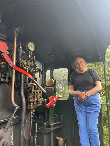
Jan on 'Wightwick Hall', 29th August 2021 (Photo: S. Wallbank)
My pictures
6989 'Wightwick Hal1'

