Layout of Locomotive
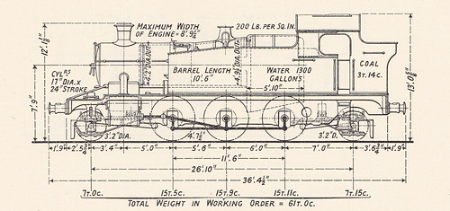
"4575" Class (Railway Publishing Co. Ltd. 1938)
Click for larger view.
In Part 1, I described oiling the motion accessible from outside of the engine at ground level. Attending to the inside motion requires the locomotive to be over an inspection pit giving access underneath the engine and allowing climbing up underneath the boiler between the frames. It doesn't matter what order oiling points are attended to but some sort of routine is necessary to ensure none are overlooked. Before disappearing into the pit, a suitable oil feeder, oil bottle of Motion Oil to allow replenishment of the feeder and the vital 'wiper' (a rag to remove any surplus oil) should be positioned in the pit or alongside the engine within reach of somebody working in the pit. This avoids having to either climb out of the pit part way through oiling to obtain supplies or shouting to your mate for assistance.
5542 has a pony truck at each end and, as you enter the pit, the oil fillers for the underkeeps on the pony truck axleboxes at that end face you as a reminder to check levels and periodically use a siphon to remove any water (which sinks to the bottom of the axlebox, being denser than the oil).

5542: Trailing truck, RH axlebox.
Most locomotives have an extensive system of rods and transverse shafts a few inches above rail level to allow all the brake shoes to be operated from a single power brake cylinder. In 5542 it's a steam brake cylinder mounted under the cab. Other British designs may use one (or two) vacuum brake cylinders and, particularly on steam locomotives used overseas, the power brake cylinder may be operated from pressurised air. Then, depending upon the design, there are additional obstructions from the suspension and various pipes. The chassis for the pony trucks on 5542 have to be ducked under, whichever end you approach from. Since 5542 also has mechanical linkages for remote control of the regulator when working 'Push-pull' or 'Auto' trains, there are also additional shafts and bell cranks to be avoided.
When moving around in the pit, it's necessary to bend down to avoid a nasty crack from contact with all this old iron. Traditionally, enginemen wore flat caps or the 'greasetop' hat during preparation, neither of which offers much protection against impacts to the head. A complication at Shackerstone is that the pit is not as deep as most pits, so a particularly hunched-up pose is required.
This rather-ape-like stance puts you at about the right level for attending to the underkeeps of the six coupled wheels which are provided with a short 'elbow' closed with a cork allowing any water to be removed with a siphon.
The next problem is to decide where to climb up into the space underneath the boiler not occupied by the inside motion or the various 'additional obstructions', to allow oil to be applied to the numerous oiling points. Depending upon stature and fitness, different people may adopt different solutions. I generally clamber up first ahead of the trailing coupled axle and then to the rear of the leading coupled axle.
A wooden stool with a single step is dragged into position in the pit ahead of the trailing coupled axle. This task is often harder than it sounds as the preparation pit is also used for disposal, so there is usually a pile of ash just where you'd like to set the stool. Feeder and oil bottle are then placed where they can be reached after you've ascended. Climbing onto the stool then puts the trailing coupled axle at about waist height so I then hoist myself up so as to sit on the axle, facing the driving axle with its four eccentrics. Leaning forward, I can first top-up the four eccentrics and then, reaching up left and right, attend to the four-feed oilboxes mounted on the inside of the main frames. The four tail trimmings in each oilbox feed a driving axlebox, via flexible hoses (2 for hornguides, 2 for axlebox) which allow for the up-and-down motion of the axlebox in the hornguides.

5542: Driving axle showing RH eccentrics.

5542: Four-feed oilbox mounted on the inside of the right main frame for Right Driving Wheel.
Having completed this part of the oiling, it's time to climb down into the pit and re-position the wooden stool, feeder and oil bottle to allow me to climb up again to sit this time on the leading coupled axle, facing rearwards, allowing the rest of the Link Motion to be oiled. Following Churchward's example, Collett provided comprehensive arrangements for keeping the Link Motion lubricated. There's a fair bit of stretching (and grunting) to reach all the corks and top-up the oil reservoirs. Then, reaching left and right, the two four-feed oilboxes mounted on the inside of the main frames which serve the leading coupled axleboxes are dealt with. The four tail trimmings in each oilbox feed a coupled axlebox, via flexible hoses
5542: Link motion for right-hand cylinder.
 5542: Four-feed oilbox mounted on the inside of the right main frame for Right Leading Coupled Wheel.
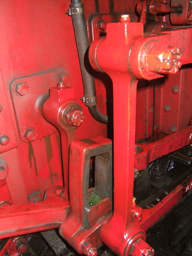
The last oiling points here are on the inner arms of the LH and RH Rocking Shafts, reached by twisting round.

5542: Upper end of RH Intermediate Valve Rod, showing connection to inner arm of Rocking Shaft.
With the rather unpleasant 'inside' examination and oiling complete, it's time to exit the pit and climb up onto the framing at the front of the engine to deal with two rocking shaft oil pots, two additional oil pots and the vacuum pump oil reservoir on the right side of the engine. The vacuum pump reservoir generally uses a steam oil and paraffin mix. On the left side of the engine there is no vacuum pump oil pot but there are two oil pots for the rocking shaft plus one additional oil pot. In Part 1, in looking at the outside motion, we'd already seen that the oiling points differ on the two sides of the engine because of the design of the slide bars and crossheads. Just below the bottom of the smokebox door, on the boiler centreline, there's a single footstep to assist the crew in reaching up to place a lamp on the top lamp iron when required. This position is always referred to as the 'chimney' but, of course, the lamp iron is actually fixed to the smokebox. Almost hidden underneath this footstep is another oil box requiring attention.

5542: View of framing on right-hand side of boiler, ahead of side-tank.
In Part 1, the Sight Feed Lubricator using steam oil is described by reference to an earlier post '5542 at the Battlefield Line'. There are also two 4-way oil boxes, in the cab fixed to the inside of the left and right side tanks at high level. The four tail trimmings in each oilbox feed a the left and right coupled wheel axleboxes via copper pipes (2 for hornguides, 2 for axlebox).

5542: 4-feed oil box mounted on the left of the cab (actually on the side tank) feeding the left trailing coupled wheel. A second, similar oil box is mounted at a lower level.
Finally, there's a low level oilbox only on the fireman's side of the cab.

5542: 4-feed oil box mounted on the left of the cab (actually on the side tank) mounted at a low level. The round 'hatch' on the left of the picture provides access to the sidetank.
Related posts on this website
Preparing 5542 (part 1).
There are also a number of other posts with technical content about working on 5542:-
GWR 'Light Prairie' 5542 (22-Aug-2010)
On the Footplate (5-Dec-2017)
Santa Specials at the Battlefield Line 2017 (19-Dec-2017)
5542 at the Battlefield Line (28-Aug-2018)
Battlefield Line 'Family Fun Weekend' (3-Sep-2018)
5542 at the Battlefield Line in 2019 (30-Jul-2019)
To see all my posts about the Battlefield Line, select Label 'Battlefield Line' or click here.
To see all posts with Mutual Improvement Class content, select label 'MIC'or click here or look at the index at Mutual Improvement Classes (2).
My photograph albums
Where necessary, clicking on an image above will display an 'uncropped' view or, alternately, pictures may be selected, viewed or downloaded, in various sizes, from the album listed:-
5542 GWR Locomotive
