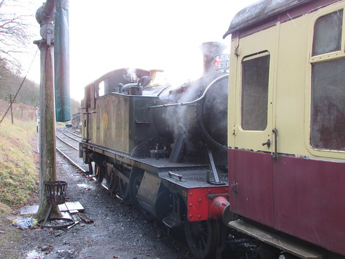
Fig 1: 5542 ready for action on 9-Dec-2017.
The (reproduction) cap badge on my locomens' greasetop reads 'LMS' which I always thought of as my 'spiritual home' (although I was only five when the LMS was absorbed into British Railways on 1st January 1948). However, my period as a volunteer at the then Birmingham Railway Museum at Tyseley gave me an abiding respect for the design of the locomotives of the Great Western Railway and, in particular, for the influence of George Jackson Churchward who was Chief Mechanical Engineer of the GWR from 1902 to 1922.
So, when I set about 'oiling round' on 'Light Prairie' 5542 at Shackerstone shed on 18th August 2018 I was reminded of Churchward's legacy in producing a range of standard locomotive designs which served the Great Western so well. Churchward was ruthless in his pursuit of reliability and efficiency and the sound detail engineering for which the Swindon Works of the Great Western became famous was immediately obvious. However, Churchward was not noted for his aesthetic sense and some of the stylistic features now admired by enthusiasts were due to members of his design team.
On most preserved railways, it is the responsibility of the fireman to perform a series of checks on the boiler before 'lighting-up'. A 'warming fire' had been left in the firebox overnight and, by the time I arrived, the fireman, Jamie, had the boiler just starting to make steam. I made my own check that the single gauge glass (embraced in its plate glass protector to protect enginemen from flying glass should the gauge glass shatter) indicated a safe level of boiler water. Most locomotives have duplicated gauge glasses but the Great Western managed with one, plus 'try cocks' as an alternative method of testing boiler water level. Swindon justified this economy by the rigorous training they gave fireman in the replacement of a failed glass tube in minutes.
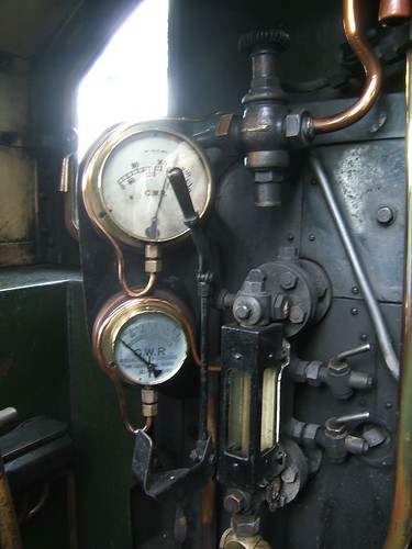
Fig 2: 5542: single Gauge Glass with Protector Note the two Try Cocks on the right of the gauge glass.
I also carried out the essential safety checks - Locomotive in mid-gear, handbrake hard on, regulator fully closed and cylinder drain cocks open. It's also usual to set wooden wheel scotches in front and behind the driving wheel on one side and display a 'Not to be Moved' board in order to prevent any movement until all staff are confirmed out of harm's way.
Sight Feed Lubricator
Moving parts in contact with steam (such as the valves, pistons and regulator valve) require lubrication with a special, compound mineral oil, formulated to retain its properties at high temperature. The sight feed on 5542 is described in a post here (use the back button to return here).
I briefly described oiling 5542 in the earlier post On the Footplate but decided to go into a little more detail this time.
Layout of Valve Gear
The 2-cylinder 'Standard' designs of the Great Western with outside cylinders all feature Stephenson Link motion with four eccentrics mounted on the driving axle between the frames to provide the necessary valve events. With inside cylinder designs, the valves are usually between the frames and can be readily driven from the expansion links via the dieblocks and valve rods. However, where outside cylinders and valves are required, a means must be provided to translate the movement of the dieblocks from inside the frames to outside the frames. Swindon devised a typically rugged arrangement using rocking shafts which is illustrated below.
 Click on the above diagram to enlarge.
Fig 3: Layout of valve gear.
The drawing above shows a tender engine: in the tank engine variant some of the proportions are altered and there's no valve spindle crosshead. The dieblock is attached to an Intermediate Valve Rod, the lower end of which is supported by a swing link. The upper end of the intermediate Valve Rod is attached to the inner of two valve arms attached to the rocking shaft mounted on the framing. The upper end of the intermediate valve rod describes an arc when driving the rocking shaft, necessitating the swing link at the lower end to accommodate this non-linear movement. The outer valve arm also describes an arc, requiring a short valve link connected to the valve spindle to accommodate the non-linear movement.
I usually start my oiling by dealing with any outside motion accessible by walking round at ground level before moving on to less-accessible parts of the locomotive. 5524 has a box for oil bottles and oil feeders mounted underneath the cab just behind the cab footsteps on the driver's (right) side of the locomotive so, having located a suitable feeder and, if necessary, topped it up from the oil bottle of Motion Oil I usually start at the trailing crankpin on the right side and then work around the engine anti-clockwise. It doesn't matter what order oiling points are attended to but some sort of routine is necessary to ensure none are overlooked.
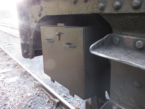
Fig 4: 5524 has a box for oil bottles and oil feeders mounted underneath the cab just behind the cab footsteps on the driver's (right) side of the locomotive.
Coupling rods have a bearing which embraces the crankpin protruding from the coupled wheel. The bearing/crankpin interface is lubricated via a delivery tube by a plug trimming set in the base of a rectangular oil box forming an integral part of the coupling rod. A large cork which prevents ingress of water and dirt is removed to add oil to the reservoir and the check or replace the trimming as necessary.
Moving forward to the right hand driving wheel, matters are more involved. In addition to the crankpin bearing on the leading coupling rod, a rearward extension connects to the trailing coupling rod via the gradient pin. The fluted connecting rod terminates in the massive big end bearing. The sheer size of the crankpin with its broad bearing area and the careful design of the arrangements immediately gives a driver confidence.
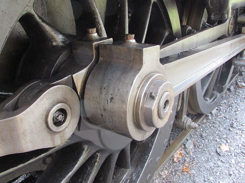
Fig 5: 5542: Right driving crankpin. Leading coupling rod has the bearing for the crankpin and a rearward extension connects to the trailing coupling rod via the gradient pin. The fluted connecting rod terminates in the massive big end bearing.
The oil box at the leading end of the front right coupling rod is frequently hidden by the connecting rod, crosshead or slide bars, depending upon the 'angle' the driving crankpin has stopped at.
The front end of the fluted right connecting rod is provided with a generous oil box (closed with a cork) to provide lubrication to the pivoting joint with the gudgeon pin which secures the connecting rod to the crosshead. However, if the big end of the connecting rod has stopped above the piston centreline, the space above this oilbox is reduced and dealing with this oiling point may have to be deferred.
The crosshead itself slides between two substantial machined slidebars attached between the cylinder block casting at the front and the massive motion bracket positioned rearwards about 2/3 along the slide bars. On the right of 5542, the lower slide bar is lubricated from an oilbox formed into the bottom of the cross head so, if the big end of the connecting rod has stopped below the piston centreline, the space above the crosshead oilbox is reduced and dealing with this oiling point may have to be deferred. The right upper slide bar on 5542 is lubricated from two cast oil pots with tail trimmings attached to the upper face of the slidebar one to the rear of the motion bracket (visible in Fig 6) and one ahead (seen on the left in Fig 7). Both these oil pots deliver oil through oilways to the lower face of the upper slidebar.
The right crosshead is provided with four hex-head bolts (visible in Fig 6 and Fig 8) which attach a drive bracket behind the slide bars for the vacuum pump so that, when the locomotive is in moving, the motion of the crosshead also drives the piston of the vacuum pump. The black-painted vacuum pump body is visible top left in Fig 6 with its piston extending forward and connected to the drive bracket. Fig 8 gives a better view of the vacuum pump drive bracket and its connection to the vacuum pump piston.
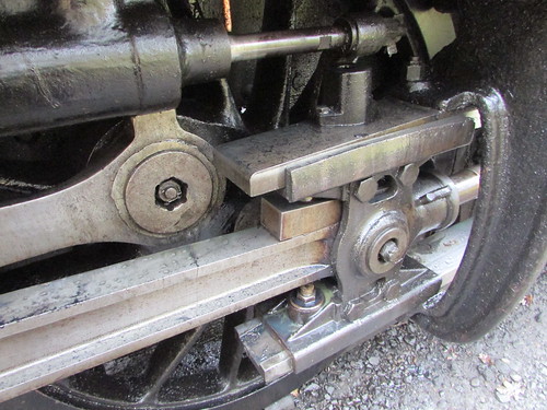
Fig 6: 5542: Right Crosshead near back dead centre.
A further complication in this area is the small oil box closed with a cork to provide lubrication to the connection at the bottom of the right outer valve arm to the rear of the short valve link and a similar oil box formed into the front of the short valve link where it connects to the right valve spindle. This is shown in Fig 7 and, again, in Fig 8 with the engine stopped in a different position.
Finally, Fig 7 also shows a second oil pot mounted on top of the right upper slide bar. In common with some patterns of oil pot, this example is closed by a tabbed flat steel cover, secured by a single screw allowing the cover to rotate so that oil can be added and the tail trimming checked. This oil box delivers oil via a vertical copper pipe to lubricate the right piston rod just to the rear of the piston gland.
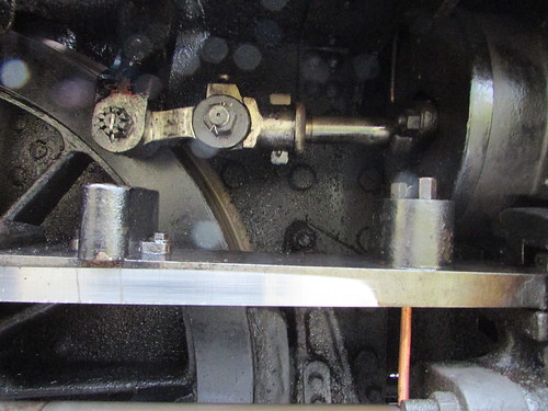
Fig 7: 5542: Front of Upper Slidebar on Right Side, with the Right Crosshead near back dead centre, showing two Oil Pots. At the top, is the outer valve arm of the rocking shaft connected via the short valve link to the valve rod.
For comparison with Fig 6, Fig 8 shows the appearance of the motion when the right crosshead is near front dead centre.
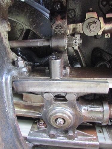
Fig 8: 5542: Right Crosshead near front dead centre, showing drive to the piston of the vacuum pump.
Now we move round the front of the engine to the left side of the engine, remembering to bring the oil feeder, oil bottle (allowing the feeder to be replenished as necessary) and all-important 'wiper' (a rag to remove any surplus oil). Completing the oiling of the outside motion on the left is largely a repetition of the process on the right but this time working from front to back. Because the motion on the left side is a quarter of a turn behind the right, oiling points which were readily accessible on the right may be hard or impossible to reach on the left (or vice-versa) so the driver must keep a careful note of any oiling which has been deferred until the locomotive can be moved.
Fig 9 below shows the left crosshead on 5542. There is no vacuum pump to drive on the left of the locomotive so (on 5542 at least) the left crosshead is a different pattern. Although the left upper slidebar is drilled to mount three oilboxes (like the right), only the leading oilbox feeding the left piston rod is fitted. The upper slidebar is lubricated from an oilbox formed into the top of the crosshead and a second oil box formed into the bottom of the crosshead serves the lower slidebar. The picture shows that the oil box at the leading end of the front left coupling rod is easily accessible but the oilbox at the little end of the left connecting rod is obstructed.
The left outer valve arm and short valve link (not illustrated) also require attention.
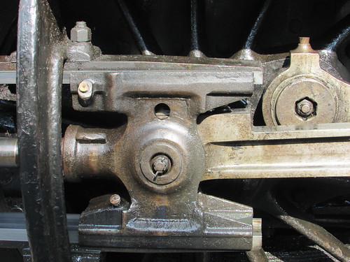
Fig 9: Left Crosshead.
Fig 10 shows the left driving crankpin with oil reservoir on the connecting rod big end, oil reservoir on the coupling rod and oil hole in the gradient pin.
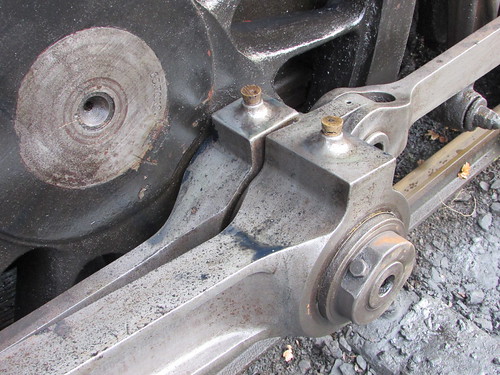
Fig 10: 5542: Left driving crankpin. Leading coupling rod has the bearing for the crankpin and a rearward extension connects to the trailing coupling rod via the gradient pin. The fluted connecting rod terminates in the big end bearing.
I've included a picture of a sister engine (4588) with connecting rods removed to show the size of driving crankpin necessary to transmit the power of each cylinder to the three associated coupled wheels. Removal of connecting rods was usually done where a 'dead' engine had to be taken a long distance. Each crosshead was wedged in a suitable position during the journey so that the pistons, piston rod and crosshead did not move and thus didn't require oiling.
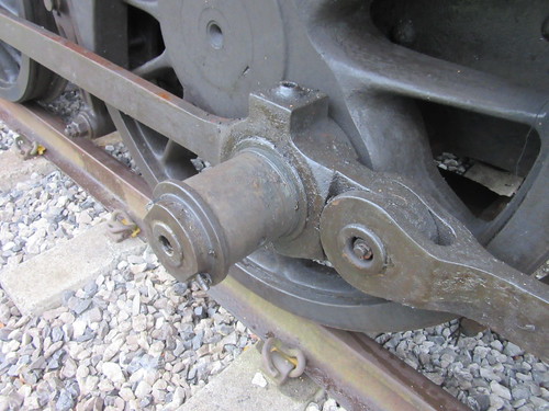
Fig 11: 4588 showing left driving crankpin with connecting rod removed pictured whilst in store at Peak Rail.
Once the oil reservoir on the rear of the left trailing coupling rod is done, that's the easy oiling finished. In the the conclusion of this article here I describe attending to the inside motion by descending into the pit underneath the engine and clambering up underneath the boiler and other necessary oiling.
Related posts on this website
Preparing 5542 (part 2).
To see all my posts about the Battlefield Line, select Label 'Battlefield Line' or click here.
My photograph albums
Where necessary, clicking on an image above will display an 'uncropped' view or, alternately, pictures may be selected, viewed or downloaded, in various sizes, from the albums listed:-
5542 GWR Locomotive
Battlefield Line, 2017-2018
All my Battlefield Line albums
[Link to part 2 added 6-Aug-2019]
