skip to main |
skip to sidebar
The Mutual Improvement Classes of the old steam railways still continue for today's preservation volunteers. This is one of a series of posts taken from notes of talks given by Jan. To find them all, select label 'MIC' or click here. There's a periodically-updated list of these posts here.
The following notes for shunters are aimed at persons working on preserved standard gauge railways in the United Kingdom. The Shunter (where I mean the person on the ground involved in marshalling a train and coupling and uncoupling vehicles - not the locomotive engaged in the marshalling), is engaged one of the more dangerous tasks carried out on a railway. This role may be carried out by dedicated shunters, by Guards or Footplate crew. Anybody carrying out this work must be suitably trained and assessed as competent and be using the specified Personal Protective Equipment (PPE).
The shunter must not go between two vehicles unless they are both stationary and there is a 'Clear Understanding' with the driver of any locomotive. Muttering "Going between" and disappearing between vehicles is not adequate - there must be an explicit acknowledgment from the driver that it is safe to go between vehicles.
Please remember "Jan's Three Rules" for working on a railway:-
1. Do it Safely.
2. Do it Safely.
3. (Can you guess?) Do it Safely.
Just moving around in a railway yard presents a challenge. The ground is rarely level and can rapidly change texture (ballast, wood, earth, paving, tarmac). There are numerous obstructions to catch out the unwary. In addition to various posts, fences and misplaced debris, there may be hand levers to operate points. If there's a signal box or ground frame in the vicinity, in addition to various types of signal there is likely to be point rodding, cranks/compensators, signal wires and signal pulleys.
This introductory part deals with the two simplest types of coupling used on freight wagons mentioning the hand brakes typically provided. In the steam era, the 3-link and 'Instanter' couplings were the most common types used on freight trains. Individual vehicles usually had hand-operated brakes, used as both a 'parking' brake and, partially applied, as a means of retarding the vehicle when descending an incline. On the move, the locomotive brake and the handbrake applied by the guard in the Brake Van at the rear of the train were the only means of controlling the train. It became mandatory on trains carrying passengers to have an 'automatic' brake operable throughout the train. Gradually increasing numbers of freight trains were fitted with 'automatic' brakes on all or at least a group of vehicles next to the engine (called a 'fitted head'), allowing higher running speeds.
The 3-link Coupling
The simplest coupling in use on standard-gauge railway vehicles in the United Kingdom comprises a strong Drawhook from which are suspended three links. Whilst easy and quick to attach or detach this type of coupling to an adjacent vehicle, there will always be 'slack' between the vehicles, and the driver must be aware of this. Because both adjacent vehicles have the same design drawhook and similar coupling links, the shunter can normally choose whether to put the left coupling links on the right drawhook or the right coupling links on the left drawhook. Should a link fail on a journey, it was possible to complete that journey by using the 'good' coupling links. However, most freight guards would keep a 'spare' 3-link coupling to hand so that a failed coupling could be replaced. Particularly in freight yards, spare 3-link couplings were often to be found lying around.
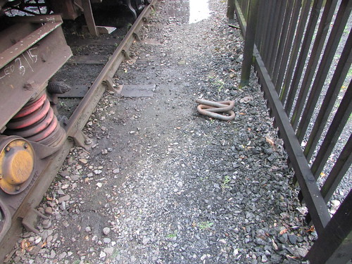
A spare 3-link coupling was often to be found lying around.
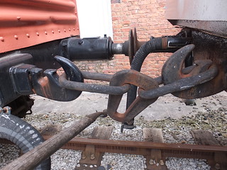
The hole in the drawhook which accepts the associated link is accessed via a 'keyway' narrower than the diameter of the steel bar from which the links are made. The prevents a coupling from becoming accidentally detached from its parent drawhook but, without special provision, this would prevent a failed coupling from being easily replaced. The 'special provision' is called the 'Kedge' - a flattening part way along a long side of the end link. This flattening makes the kedge thin enough to pass through the keyway in the drawhook, allowing the coupling to be suspended from the parent drawhook.

3-link coupling, showing the 'kedge' in the long side of the end link which allows the coupling to be suspended from the parent drawhook.
The slack in the couplings on this type of train (referred to as 'loose-coupled') can be used to advantage by a driver in starting a heavy train. If the locomotive has eased back on the train, only part of the train weight has to be moved initially with additional load taken by the locomotive as couplings tighten towards the rear of the train. However, on an undulating route, additional skill is needed as the wagons 'bunch up' on down grades and 'pull out' on rising grades. Co-operation with the Guard, in operating the handbrake in the Guard's Van, can minimise the effects.

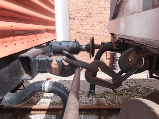
3-link or 'Instanter' Coupling: End view (from a Railtrack document).
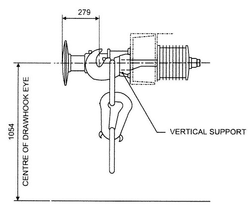
Instanter Coupling: Side view. The 3-link coupling is similar, but with a plain, oval centre link (from a Railtrack document).
The 'Instanter' Coupling
The 'Instanter' is similar to the 3-link, except that the middle link has a complex shape with two 'ears' allowing it to be placed in either of two positions, corresponding to 'long' or 'short'. In the 'long' position, the coupling has the ease-of-use of the 3-link. In the 'short' position, some of the 'slack' is taken out of the coupling and the motion of the train may be better (particularly for the Guard at the end of the train!).
Diagram of 'Instanter' Couplings in the 'Long' and 'Short' positions (From the L.M.S. General Appendix to the Working Time Tables 1937).
The Shunting Pole
The Shunting Pole was an invaluable aid to Shunters. A stout, round, wooden staff, usually made from ash was provided with a specially-shaped metal end, curled like the tail of a pig. Armed with this tool, a skilled operator could rapidly couple or uncouple both 3-link and 'Instanter' couplings. 'Instanter' couplings could also be turned from long to short or short to long positions. This was done with the shunter standing alongside the wagons so it was both safer and faster. Some strength and some practice is required to become proficient. It's also important to check the pole regularly for damage. In former times, employees were sometimes tempted to make use of shunting poles in unauthorised ways. The frequent need to apply or release wagon handbrakes could tempt the shunter to use the shunting pole as a lever (rather than the properly-designed brake stick) or, worse, to avoid chasing a wagon down a siding shunters might wedge the shunting pole into the underframe of a moving wagon and ride on the protruding pole. Serious injury or death could follow so no modern volunteer should copy these risky practices.
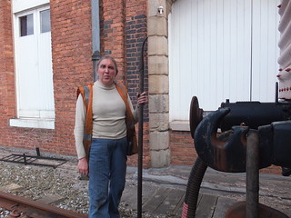
Jan at the Museum of Science and Industry, Manchester (with Shunting Pole and looking rather fierce).
The shunting pole, showing the 'business end'.
Coupling either a 3-link or 'Instanter' coupling to the drawhook of the adjacent wagon using the shunting pole. The shunting pole is held under the buffers, engaged with the bottom link and swung up and across. The shunting pole is released by twisting.
Using the shunting pole to uncouple a 'long' 'Instanter' or 3-link coupling from the drawhook of the adjacent wagon. The metal part of the Shunting Pole is placed under the link and the pole swung upwards. This is sometimes done with the pole over the buffer shank.
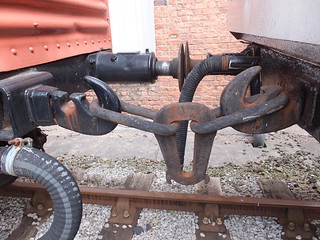
'Instanter' Coupling after turning to 'short' position. The centre link is turned, by engaging the pig's tail with one of the 'ears' on the centre link and pulling upwards.
'Instanter' coupling: Using the shunting pole to place an 'Instanter' coupling in the 'long' position. Beforehand, there must be sufficient slack in the coupling to allow the centre link to be turned, by engaging the pig's tail with one of the 'ears' on the centre link and pulling upwards.
Wagon Brakes
Freight wagons are provided with hand-operated brakes, usually capable of being applied from either side using a long, pivoted brake lever but short levers or handwheels are also used. Even with a long brake lever, significant downward force may be needed to apply the brake effectively. The Brake Stick (described below) can assist in safely applying and releasing handbrakes. There's a little more about brakes on railway vehicles here and pictures of a range of preserved wagons in the album Freight Rolling Stock.
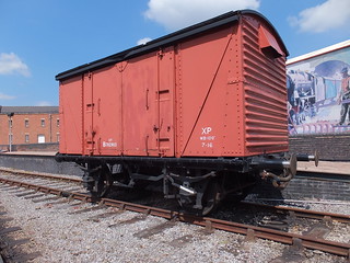
A typical 4-wheel Van (or Covered Wagon) provided with a handbrake lever on both sides. Operating either lever downwards applies the brakes but both levers must be raised to release the brakes.
Detail of handbrake lever, showing the pin and chain used to 'pin down' the brakes when parked or descending an incline.
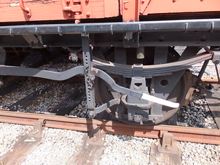
Detail of tranverse brake shaft, showing how the handbrake lever on either side applies a strong force to a cam to turn the transverse shaft and apply the brakes.
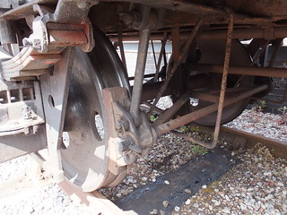
Detail of brake rigging, showing cast iron brake blocks.
The Brake Stick
The Brake Stick is wooden, about 3 feet long. Half the length is rectangular, around 2.5 inches by 2 inches in section. The remainder is rounded and tapered to about 1.25 inches diameter at the end. The rectangular section is placed over the Brake Lever and wedged under the underframe or the spring. Pressing down on the rounded section provides additional leverage and the pin is inserted in a pair of holes to retain the brake force. The brake stick may be needed to safely remove the pin when it is necessary to release the brake. As with the Shunting Pole, it's important to check the Brake Stick regularly for damage.
More on this topic at The Role of the Shunter (2).
Related posts on this website
MIC - Brakes.
Related photograph albums
Pictures from may be selected, viewed or downloaded, in various sizes, from the album listed:-
Freight Rolling Stock.
On Saturday 12th August 2017, I was back at the Battlefield Line, this time on 'Cumbria' which had recently had a washout and repairs to the fireman's side injector.
There was no footplate experience course booked so it was a leisurely start for me signing on at 08:30, although Adrian L. (who was acting as fireman in the morning) had arrived a couple of hours earlier to get the engine lit-up. In addition to the normal service of five return trips between Shackerstone and Shenton, in the evening there was a 'Fish and Chip Special' which I'd also agreed to 'cover'.
I 'oiled round' and examined 'Cumbria' and we were 'off shed' in plenty of time to attach to our 4-coach train waiting in platform 2 at Shackerstone. After the first two round trips to Shenton, Adrian was replaced as fireman by Steve A. But Adrian had not finished - on the contrary, donning his 'catering' hat, he and Gina spent the afternoon sorting out supplies for the evening 'Fish and Chip Special' whist Steve and I completed the normal 'diagram' with another three journeys to Shenton and back.
Arriving back at Shackerstone after our fifth trip, we were routed into platform 1 where the main station facilities (tea room, museum and toilets) are located. I deliberated 'stopped short', leaving room at the north end of the platform for our train to be 're-inforced' with an additional coach for the fully-booked evening special. Steve uncoupled 'Cumbria' and we went to the north end sidings to 'coal-up'. The bucket loading shovel (driven by Adrian wearing another 'hat') soon topped-up our bunker. We then shunted south through platform 2 to replenish the saddle tank from the water crane at the at the south end of platform 2. In defiance of normal conventions, turning the wheel which controls the water valve clockwise opens the valve, rather than closing it. Many years ago, as a reminder, somebody wrote on the wheel in white paint 'Open' and 'Closed' with arrows but this is now faded. If I'm on the wheel, I always have to do a 'double-take' when I hear the cry "That'll do" from my mate on top of the tank to avoid both of us getting a soaking.

Water Crane at Shackerstone. The wheel which controls the water valve is on the right.
Coaled and watered, we coupled onto the south end of the four coaches we'd left in platform 1 and I was able to watch the shunting being performed. The maroon-painted coach to be added to our train was behind the self-powered Tamping Machine in siding 2 at the north end so Adrian (now with driver's 'hat') 'fired-up' the tamper and moved into platform 2, pulling the extra coach. The Class 04 diesel shunter moved onto the north end of our train and attached the nearest coach (a 'Mark 1' in Western Region 'chocolate and cream' livery), first drawing it back to the north end, then propelling it onto the maroon-coach behind the tamper in platform 2. The '04' then pulled both coaches back to the north end, before finally propelling them towards the coaches waiting in platform 1.

Adrian leaning out from the '04', checking for handsignals from the shunter, as he propels two coaches onto the three already in platform 1.
British passenger coaches built after the 1948 Nationalisation of railways were fitted with 'Buckeye' couplings, retaining a conventional drawhook which is used to attach the locomotive using a screw coupling (only one British steam class was originally fitted with 'Buckeye' couplings - Gresley's 'A4'). On coaches, the 'Buckeye' is hinged and has to be lifted to the horizontal position to allow coupling to a similarly-fitted vehicle. The substantial hook has a hinging 'knuckle'. To couple, two vehicles are brought together with one of the knuckles in the 'open' position and the adjustable buffers set to the 'Short' position.
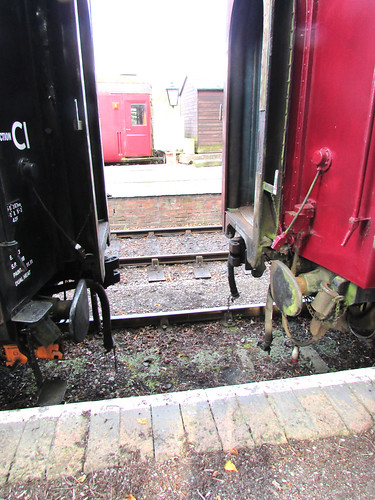
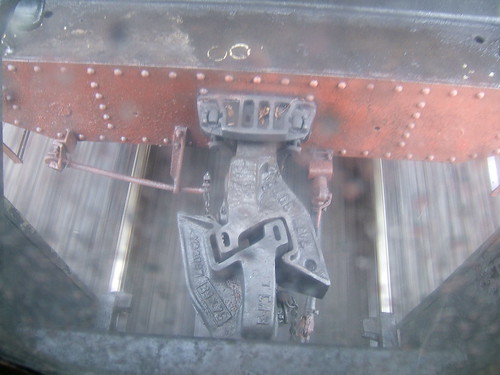
BR Coaches being shunted together. Buffers in 'Short' position for use with Buckeye coupling. Note 'saddle' stowed on bracket adjacent to buffer.
As the two couplings contact, the open knuckle is forced closed and a mechanical latch drops, locking the knuckle closed. In addition to the shunter confirming visually that 'the pin' has dropped, a 'pull test' is conducted where the locomotive tries to separate the vehicles. Unfortunately, to connect the brake hoses and, when required, the steam heating hoses, the shunter still has to clamber underneath the vehicles. The electrical jumpers to allow the guard to control the carriage lighting also require connection.
To uncouple, pulling a chain on either coupling unlatches that knuckle, allowing the vehicles to be drawn apart. The shunter controls the coupling and uncoupling by hand signals given to the driver of the locomotive performing the shunt from a position alongside the vehicles.
It was a warm summer evening and, by this time, a good-natured crowd of expectant diners had assembled on the platform, waiting to be seated on the train. Steve and I readied 'Cumbria' for a leisurely trip down the line.

'Cumbria' ready to depart with the evening train.
A little late, we received the 'Right Away' from the Guard, collected the Single Line Staff from the Signalman at Shackerstone and trundled down the line. We were not expecting to stop at Market Bosworth but, as we approached the platform, one of our Volunteers was on the platform so we decided to make a stop. He didn't board the train, but had apparently ordered a portion of fish and chips which was safely delivered to him, after which the Guard gave the 'Tip' and we set off again.
I'd been told to stop on Shenton Bank, just before our last station, where there are views across the Leicestershire countryside on both sides of the train. It was a perfect summer evening as the sun sank lower in the sky and the engine simmered quietly whilst our diners enjoyed their food. I felt much happier than the picture below perhaps suggests.
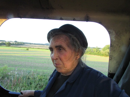
Battlefield Line Fish and Chip Evening Special: We paused on Shenton Bank with views across the Leicestershire countryside.
Food had also been ordered for the loco crew, so Steve 'dropped down' and walked back to collect our fish and chips which we enjoyed whilst waiting. After about fifteen minutes, the Guard gave us the 'Right Away' and we continued to Shenton station. There was then a bout of activity as we uncoupled, ran round and coupled onto the train for the journey back to Shackerstone. Many of our passengers were on the platform, enjoying the warm evening and taking numerous photographs. Once everyone was back on board, we set off on a fairly gentle trip back to Shackerstone.
We arrived back in platform 1, stopping so that all the passenger coaches were in the platform. With 'five on' that meant that the rear of the train didn't leave sufficient clearance for us to use the ground frame giving access to the loco shed. So we ran round, attached to our train and, with the Guard giving hand signals from the north end, propelled the train northwards a short distance to give sufficient room for us to get 'onto shed'. By this time, it was fairly dark. It only remained to put the locomotive in the shed and carry out the normal disposal routine after what had been a very enjoyable day.
Related posts on this website
To see all my posts about the Battlefield Line, select Label 'Battlefield Line' or click here.
My photograph albums
Where necessary, clicking on an image above will display an 'uncropped' view or, alternately, pictures from may be selected, viewed or downloaded, in various sizes, from the albums listed:-
Battlefield Line Fish and Chip Evening Special.
'Cumbria'.
All my Battlefield Line albums.
The Mutual Improvement Classes of the old steam railways still continue for today's preservation volunteers. This is one of a series of posts based on notes of talks given by Jan or with technical content which may be of use to today's volunteers. To find them all, select label 'MIC' or click here. There is also a list of these posts (not always up-to-date) here.
There is an earlier post which introduces the role of the shunter here and the comments on safety in that post equally apply here. The introductory post discussed simpler coupling systems widely used on standard-gauge freight rolling stock. This part discusses couplings used on passenger rolling stock.
Screw Couplings
Whilst the 'loose coupling' provided by three-link couplings was acceptable on freight trains, passenger vehicles needed to be more tightly coupled to give a reasonable level of comfort. For many years, passenger coaches in Britain used 'screw-couplings'.
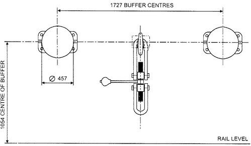
Vehicle with Screw Coupling hanging: End view (from a Railtrack document).
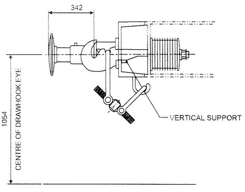 Vehicle with Screw Coupling stowed on hook: Side view (from a Railtrack document).
Once the coupling is on the drawhook of the adjacent vehicle, it is tightened up by rotating a threaded screw which has one end with a left-hand thread, the other end with a right-hand thread, using a built-in tommy bar incorporating a counterweight. This draws the two D-links together tightening the coupling so that, on straight track, the buffers will be equally compressed but, on curves, the buffers on the inside of the curve will be further compressed and the buffers on the outside of the curve will slacken slightly. At all times, the buffers should remain under some compression, so that the train cannot bang in and out. The comfort of the passengers depends upon the screw adjustment being correctly carried out. The complete process of coupling vehicles is outlined in the article On the Footplate (Part 2).
The picture below shows restored L.M.S. coach 7828 attached to 'Austerity' Tank 'Lord Phil' at Peak Rail.
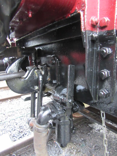
Restored coach 7828 at Rowsley: View showing coach drawhook, with unused coach 'D' link hanging down. The rest of the stowed coach screw coupling is obscured by the steam heating hose. The coach has been attached to 'Austerity' Tank 'Lord Phil' using the locomotive coupling.
Although screw couplings were effective, the results of accidents, particularly at higher speeds, showed the limitations of screw couplings. Part of the train could twist or even break free, increasing the chance of serious injuries.
Automatic Couplings
In other countries, various forms of 'Automatic' coupling had been developed to provide extra strength and simplify the business of coupling and uncoupling vehicles. In America, Eli Janney patented his design in 1873 and, in 1893, legislation made this the standard coupling in America. In 1915, John Willison of Derby patented his own automatic coupling which, with modifications, was adopted in 1935 by the Soviet Union as their standard coupler.
Ukraine Steam: Locomotive Em 735-72 at speed in the rain, showing Russian pattern autocoupler between tender & coach.
A variation of the Janney coupling with side release called the 'Buckeye' was adopted by the L.N.E.R. and the Southern in the 1930s, retaining side buffers. Since not all vehicles were fitted with 'Buckeye' couplings (and only one class of British steam locomotives was fitted - Gresley's 'A4'), the 'Buckeye' fitted to coaches was a 'drophead' pattern where the automatic coupler head could be lowered to reveal a conventional drawhook for use with a screw coupling. After the 1948 Nationalisation of British railways, a range of standard passenger coaches were built, similarly fitted with a conventional drawhook, 'drophead' 'Buckeye' coupler and adjustable side buffers (each with two positions - 'long' for use with a conventional screw coupling and 'short' when using the 'Buckeye').
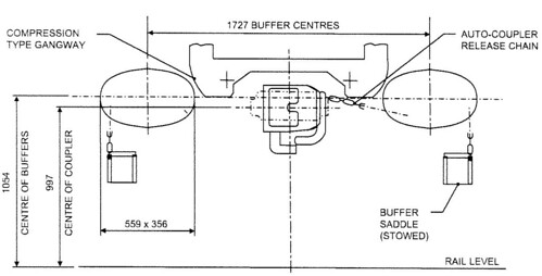
Buckeye Coupling as fitted to B.R. Mk 1 and Mk 2 gangwayed vehicles: End view (from a Railtrack document).
Buckeye Coupling as fitted to B.R. Mk 1 and Mk 2 gangwayed vehicles: Top view (from a Railtrack document).

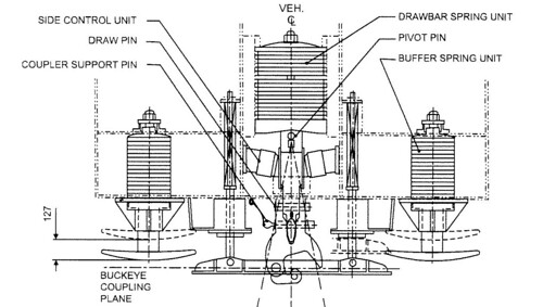
Buckeye Coupling as fitted to B.R. Mk 1 and Mk 2 gangwayed vehicles: Side view (from a Railtrack document).
The 'Buckeye' has a substantial hinging 'knuckle'. To couple, two vehicles are brought together with one of the knuckles in the 'open' position and the adjustable buffers set to the 'Short' position, as shown in the picture below.
BR Coaches being shunted together. Buffers in 'Short' position for use with Buckeye coupling. Unused 'saddles' are stowed on a bracket adjacent to each buffer.
As the two couplings contact, the open knuckle is forced closed and a mechanical latch drops, locking the knuckle closed. In addition to the shunter confirming visually that the 'pin' has dropped, a 'pull test' is conducted where the locomotive tries to separate the vehicles.
To uncouple, pulling a chain on either coupling head unlatches that knuckle, allowing the knuckle to swing open and the vehicles to be drawn apart.
When coupling or uncoupling the shunter stands alongside the vehicles and controls the movement by hand signals given to the driver of the locomotive performing the shunt. Unfortunately, to connect or disconnect the brake hoses and, when required, the steam heating hoses, the shunter still has to clamber underneath the vehicles, after coming to a clear understanding with the driver that it is safe to do so. The electrical jumpers between vehicles which allow the guard to control the carriage lighting also require connection/disdconnection.
Related posts on this website
The Role of the Shunter (Part 1).
On the Footplate (Part 2).
MIC - Brakes.
Mutual Improvement Classes (2) (List of MIC posts).
My photograph albums
Where necessary, clicking on an image above will display an 'uncropped' view or, alternately, pictures from may be selected, viewed or downloaded, in various sizes, from the albums listed:-
Passenger Rolling Stock.
['Related posts' amended 13-Apr-2020]
In 2013, the Brewood Village Garden Party annual event was restarted, re-located to the garden at Brewood Hall. Deemed a success, it has been held in 2014, 2015, 2016 and, as described below, on Saturday, 8th July 2017.
Preparations
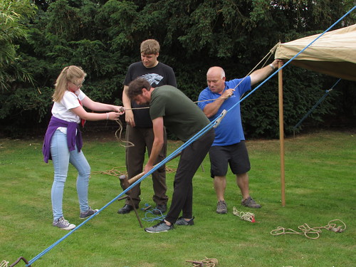
Each year significant effort by volunteers, which starts months earlier with a series of planning meetings, is needed to ensure that people enjoy their visit to the event. In 2017, erection of the tents commenced two days before the Garden Party.
Brewood Garden Party 2017: The Refreshment Tent takes shape.
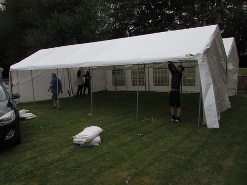
Preparations continued on the evening before the event. These included the erection of the large marquee which would serve as the 'Craft Tent'.
Brewood Garden Party 2017: Putting up the large Marquee.
The Event
Once again, the weather was kind on the day of the event and visitors started to arrive at the entrance gate a little before noon.

Brewood Garden Party 2017: The Admission table.
The Refreshment Tent was soon busy and remained busy. The combination of covered and open air tables, with the Pimm's Tent nearby, catered for all tastes.
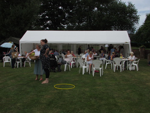
Brewood Garden Party 2017: The Refreshment Tent is always popular.
For the first time, food was also available from a 'Pizza Van' which used a traditional wood-fired oven. This was a very successful innovation and many people commented favourably on the quality of the pizza.
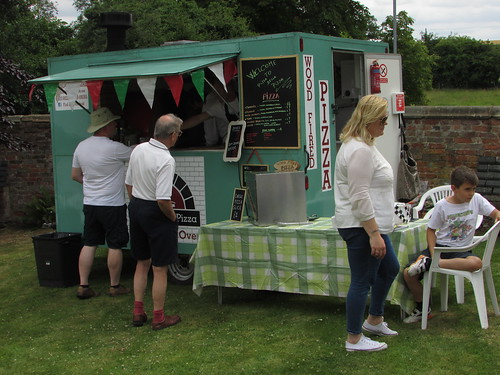
Brewood Garden Party 2017: A successful innovation in 2017 was the 'Pizza Van', using a traditional wood-fired oven.
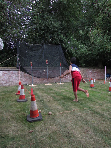
Traditional entertainments included wet sponge throwing at a human target and the ever-popular coconut shy. There was also a catapult range and a supervised Under-5 Play Zone.
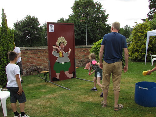
Brewood Garden Party 2017: Traditional entertainments included wet sponge throwing at a human target.
Brewood Garden Party 2017: The coconut shy is popular with all ages.
The Craft Tent featured the work of a number of local artists and crafters whilst the well-stocked Plants and Produce stall organised by the parish church provided shopping opportunities.
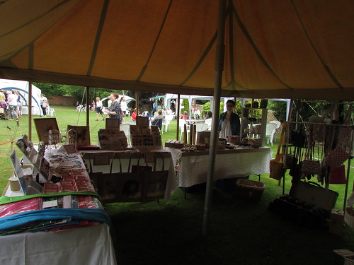
Brewood Garden Party 2017: The Craft Tent featured the work of a number of local artists and crafters.
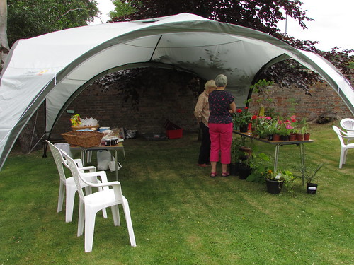
Brewood Garden Party 2017: The well-stocked Plants and Produce stall organised by the Parish Church provided shopping opportunities.
For the first time, Black Country Live Steamers displayed two marvellous live-steam scale models of traction engines, which created a lot of interest. You can read more about Black Country Live Steamers on their website here.

Brewood Garden Party 2017: Live-steam scale model of a Fowler traction engine, with a young admirer.
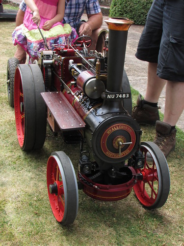
Brewood Garden Party 2017: Live-steam scale model of an Allchin traction engine.
An unexpected "visitor" was the preserved World War II Lancaster Bomber from the Battle of Britain Memorial Squadron, which overflew our event. You can read all about this historic arcraft on the website here.
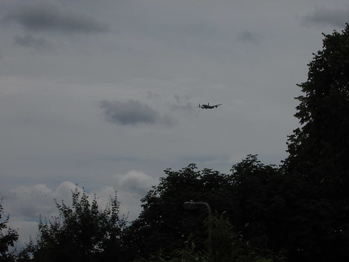
The preserved World War II Lancaster Bomber overflew the Garden Party.
As in previous years, live music was provided by the talented young musicians from the Cannock Wind Band and the Cannock Big Band who are based at the Cannock Performing Arts Centre.
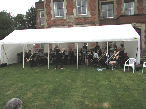
Brewood Garden Party 2017: Live music was provided by the Cannock Wind Band and the Cannock Big Band.
Later, a contingent from the Staffordshire Corps of Drums gave a demonstration. Captain Keates provided a virtuoso drum performance, accompanied by what I call a marching glockenspiel (but which I learn is also known as a Bell Lyre or a Lyra Glockenspiel - see Wikipedia here).
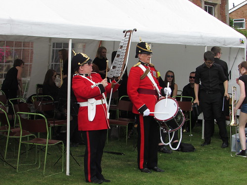
Brewood Garden Party 2017: A contingent from the Staffordshire Corps of Drums gave a performance.
As in previous years, a series of Sack Races and Egg and Spoon Races for children were held and, once again, proved popular. All the entrants were enthusiastically supported by the visitors. Each of the competitors was awarded a selection of confectionery,
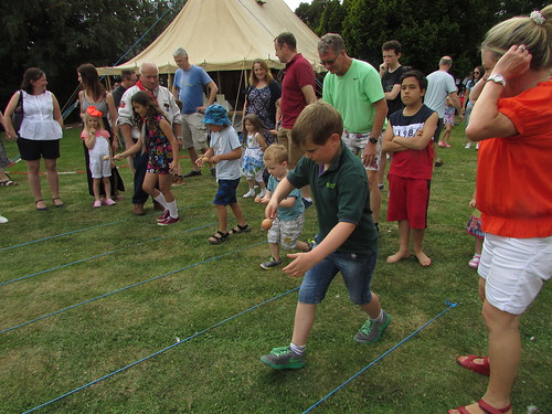
Brewood Garden Party 2017: The children entering the Sack Races and Egg and Spoon Races were enthusiastically supported by the visitors.
Everybody agreed that, once again, we'd had a very successful event (and the sun shone). This year, the organising committee made four awards - a special award to Compton Hospice and awards to Brewood Scouts, the Brewood Parish Church and the Jan Ford Foundation.
Reports on earlier garden parties at Brewood Hall
Brewood Vintage Garden Party 2013.
Brewood Vintage Garden Party 2014.
Brewood Garden Party 2015.
Brewood Garden Party 2016.
Related posts
More information on the charitable work supported by the Jan Ford Foundation in Myanmar (formerly Burma) can be found by following the links below:-
Education Support
Medical Support.
Pictures of the event
Where necessary, clicking on an image above will display an 'uncropped' view or, alternately, pictures from may be selected, viewed or downloaded, in various sizes, from the album below:-
Brewood Garden Party 2017.
Each year, The Old Locomotive Committee (OLCO) has an event for live steam models of the 'Lion' locomotive.
In 2017, the event, called 'Lionsmeet', was held on Saturday, 22nd July at the Worden Park track of the Leyland Society of Model Engineers.
I travelled to Preston on an Edinburgh train which I joined at Wolverhampton. The journey, operated by Virgin using two 5-car 'Voyager' diesel-electric units, was swift and on-time (although it never ceases to irritate me that so many long-distance journeys 'under the wires' remain operated by diesel traction). I first spent a while exploring Preston city centre on foot - still strangely quiet as early morning shoppers started to fill the streets. I walked as far as the Harris Museum and Art Gallery, with its all-embracing, gilded, carved inscription
'TO LITERATURE ARTS AND SCIENCE'.

The famous Harris Museum and Art Gallery in Preston.
Then, I retraced my route back to the station and took a taxi south of the city centre to Leyland. The taxi dropped me at the Park Gate and I had a walk of a few hundred yards to reach the Club House and Steaming Bays but, fortunately, my 'railway homing instinct' did not fail me.
I was welcomed by Andrew Neish, who is currently the 'Lionsmeet' organiser for OLCO and the other early arrivals. Members of the host club were also there in force and I was soon drinking a welcome cup of tea in the clubhouse.
The club has established a 1617 foot continuous raised track for 3½ and 5 inch gauge models (arranged as a 'folded dumb-bell') and a ground level 7.25 inch track extending to one kilometre (laid out as a 'slightly-bent dumb-bell'). There are covered steaming bays, turntables and station facilities for each gauge.
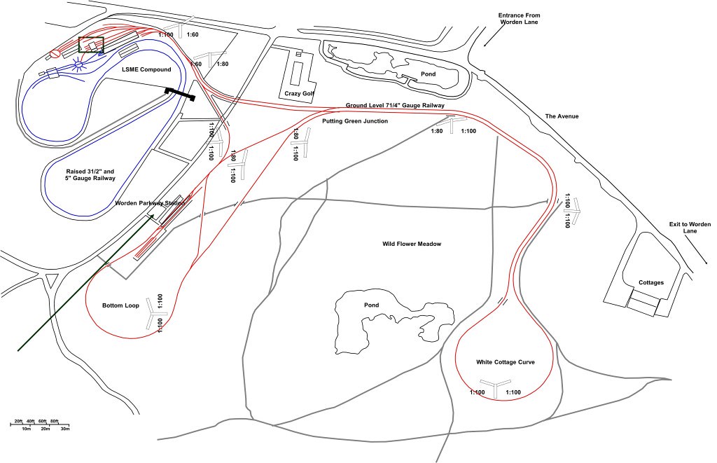
Click for larger image
Worden Park, Leyland: Plan of model railway facilities. (Map: Leyland Society of Model Engineers).
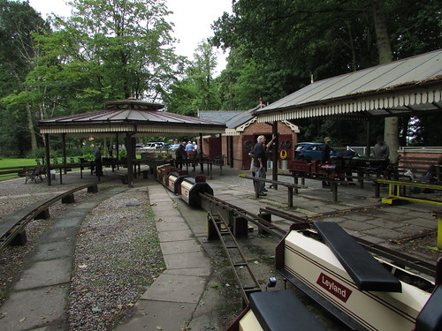
'Lionsmeet 2017' at Leyland SME: View looking west from the Stock Shed towards the 3½in and 5in steaming bays with the 7.25in steaming bays on the right.
My eye was drawn to an impressive 7.25in model of 60809 'The Snapper', brewing-up in the steaming bays. I learned that this would be giving public rides during the day on the ground-level track. Soon, a 7.25in 'B1' was also being steamed.
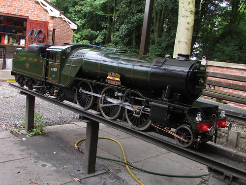
'Lionsmeet 2017': 7.25" gauge locomotive 60809 'The Snapper' being prepared for service on the ground level track.
Although we've had 7.25in gauge 'Lion' models in steam at some previous 'Lionsmeets', none attended in 2017 and so the OLCO activities were confined to to raised track. Club members first extracted their battery electric locomotive 'Worden Ranger' from its 'garage' (where battery charging takes place) and marshalled a train of two passenger car and a 'tool car'.
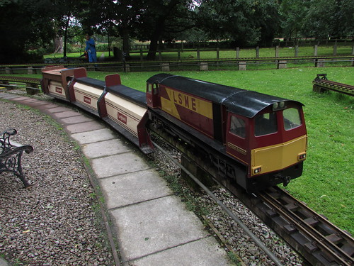
'Lionsmeet 2017' at Leyland SME: The Battery Electric locomotive 'Worden Ranger' ready to perform a line inspection of the elevated track, with two passenger cars and a tool car.
After the line inspection was completed, I was invited to make a couple of circuits with 'Worden Ranger'. Driving was straightforward, with just a direction selector and a single power controller handle. The handbrake on the leading passenger car was used for train braking although there was also a 'parking brake' on the locomotive. I found the locomotive responsive and powerful. A (rather feeble) two-tone horn was provided. For part of the morning, the host club gave public rides with 'Worden Ranger' and its train but the raised track was generally reserved for OLCO members.
Models were steamed by David and Andrew Neish, Jon Swindlehurst and Adrian Banks. David and Andrew, as usual, alternated in driving David's model.
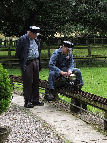
'Lionsmeet 2017' at Leyland SME: David Neish and Andrew Neish on the elevated track.
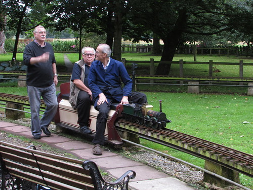
'Lionsmeet 2017' at Leyland SME: Jon Swindlehurst about to depart with his 'Lion' with John Oliver as passenger.
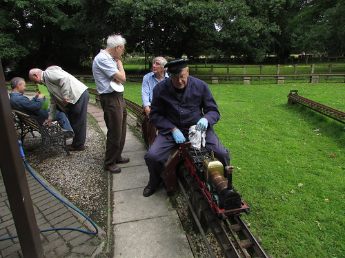
'Lionsmeet 2017' at Leyland SME: Adrian Banks pauses adjacent to the steaming bays whilst he 'fettles his fire', allowing his passenger, John Brandrick, to chat to John Hawley.
In addition, a number of part-built 'Lions' were displayed in the Club House. David Forrest's beautifully-built model (on the right in the picture below) attracted many favourable comments. He had produced a number of trial '3D-Printed' plastic components during the development of his design.
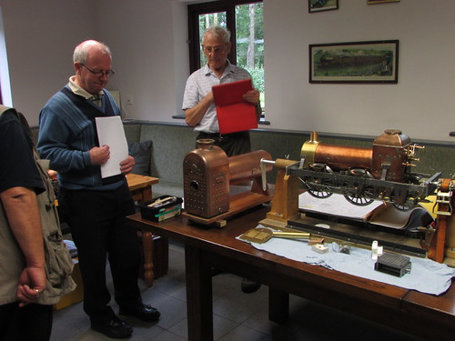
'Lionsmeet 2017' at Leyland SME: Discussions in the Club House: John Oliver, David Forrest, John Hawley.
The host club laid on a splendid buffet lunch and free-running of the models in steam continued into the afternoon. OLCO Chairman John Brandrick made a short address of thanks to Leyland S.M.E. for their hospitality, following one minute's silence to commemorate the death of Justin Garside-Taylor from the Museum of Liverpool.
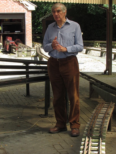
'Lionsmeet 2017' at Leyland SME: During the afternoon John Brandrick, Chairman of OLCO, made a short address of thanks to Leyland S.M.E. for their hospitality.
Some of the OLCO visitors made their way across to the 7.25 inch ground level track at the adjacent Worden Parkway Station, where rides were given to the public throughout the day. In the morning, 'The Snapper' was the motive power but, by the time John Hawley and I went across, B1 'Reedbuck' had taken over.
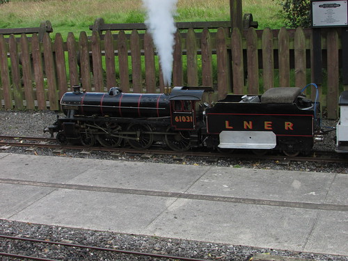
'Lionsmeet 2017' at Leyland SME: Worden Parkway Station on the 7.25 inch ground level track showing 'B1' 61031.
John Hawley kindly ran me to Preston Station for my return train, so I missed the informal 'OLCO Dinner' held later in Euxton.
Related posts on other websites
Leyland Society of Model Engineers.
Related posts on this website
All my posts regarding the Old Locomotive Committee can be found here, with links to my pictures.
My pictures
Where necessary, clicking on an image above will display an 'uncropped' view or, alternately, pictures from may be selected, viewed or downloaded, in various sizes, from the albums listed:-
Lionsmeet 2017.
Preston.
All my 'OLCO' albums.


