skip to main |
skip to sidebar
The success of the 1931 project to electrify the Manchester South Junction & Altrincham railway (briefly described here) encouraged the L.N.E.R. to proceed with their plans for electrification of the main line between Manchester and Sheffied but World War II delayed completion of this project. After World War II, the long-planned scheme introduced main line overhead electrification at 1500 volts d.c. The majority of the electrified line was opened by 1954. Freight trains were single-headed or double-headed by one or two of the original class 'EM1' Bo-Bo locomotives (later TOPS classification was Class 76). Passenger trains were hauled by class 'EM2' Co-Co locomotives (later TOPS classification was Class 77).
I was a volunteer at the Science and Industry Museum in Manchester (MOSI) for many years (you can find all my posts about the Museum here). A complete cab from an 'EM1' locomotive was displayed in the Power Hall at MOSI. However, on my last visit to the museum in 2022 (described here), many exhibits, including 'Ariadne' were not viewable because of a 'multi-million-pound restoration programme' in progress.
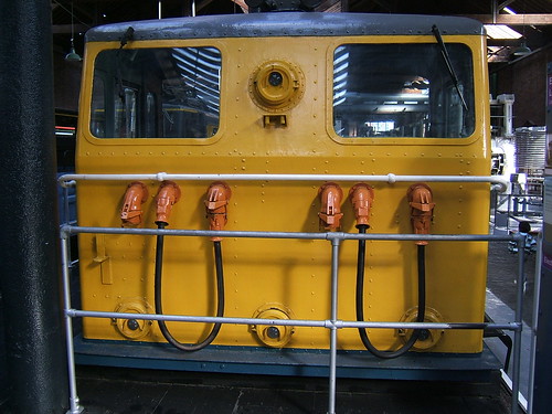
One cab of the ex-Manchester, Sheffield, Wath 'EM1' electric locomotive 76039 has been preserved in British Rail blue livery.

Ex-Manchester, Sheffield, Wath 'EM1' electric locomotive 76039 preserved cab in British Rail blue livery with later running number and worksplate

Driving desk of preserved cab. The reflections from the various surfaces produce a rather confused result, sorry.
The 'EM1' Bo-Bo locomotives had four 467 horse power Metropolitan Vickers d.c. motors. Pair of motors on each bogie were permanently in series. For starting, all four motors were in series with 15 starting resistors in series. 'Notching-up' progressively removed these resistors. The two pairs of motors were then placed in parallel with the starting resistors re-instated. Further 'notching-up' progressively removed the resistors. Final acceleration was achieved by weakening motor fields by switching-in a resistor. The drawing below includes the mechanical drawing, wiring drawing and control table.

Click for larger view
'EM1' Electric Locomotive (from 'Metro-Vick Locos 1954' in Railway Archive)
Related posts on other websites
British Rail Class 76 (Wikipedia).
The Electric Bo-Bo Class EM1 (BR Class 76) Locomotives (LNER Encyclopedia).
Related posts on this website
Class 'EM2' D.C. Electric
An undetected text error resulted in this post claiming to describe the 'EM1' class for some months. I'm sorry.
The success of the 1931 project to electrify the Manchester South Junction & Altrincham railway (briefly described here) encouraged the L.N.E.R. to proceed with their plans for electrification of the main line between Manchester and Sheffied but World War II delayed completion of this project. After World War II, the long-planned scheme introduced main line overhead electrification at 1500 volts d.c. The majority of the electrified line was opened by 1954. Freight trains were single-headed or double-headed by one or two of the original class 'EM1' Bo-Bo locomotives (later TOPS classification was Class 76). Passenger trains were hauled by class 'EM2' Co-Co locomotives (later TOPS classification was Class 77).
A complete 'EM2' named 'Ariadne' is preserved at the Science and Industry Museum in Manchester (in addition to one at Midland Railway Centre and one at Utrecht Railway Museum). The Manchester locomotive is 27001 (later E27001) built at Gorton in 1953 which when withdrawn was sold to the Dutch railways, Nederlandse Spoorwegen (NS) in 1969 for further service in Holland. On withdrawal by NS, the locomotive returned to Manchester where it is displayed with its NS running number (1505) and in NS livery. However, on my last visit to the museum in 2022 (described here), many exhibits, including 'Ariadne' were not viewable because of a 'multi-million-pound restoration programme' in progress.

Ex-Manchester, Sheffield, Wath type 'EM2' electric locomotive 'Ariadne' in its NS (Dutch Railways) livery.
I was a volunteer at the Science and Industry Museum in Manchester for many years (you can find all my posts about the Museum here). On rare occasions, it was necessary to shunt 'Ariadne' from its normal location in the Power Hall for one reason or another by coupling the electric to another locomotive, either the battery electric shunter or a steam locomotive. I was involved a few times as Shunter or Driver. I never saw 'Ariadne' move under her own power.

Preserved Battery Electric locomotive: General view in Central Electricity Generating Board livery.
A few of the volunteers had made sure that all the auxiliaries, switchgear and the pantograph (the locomotive was parked under a short section of 'dead' overhead contact wire) were kept in working order so that everything could be exercised and 'driving' practised, without actually moving the locomotive. I was told that, before I became a member, an enterprising volunteer had rigged cables from the batteries in the site's battery electric shunter to 'Ariadne', coupled the two together and had driven the combination from Ariadne's cab up and down the site, to the consternation of The Powers That Be, who quickly put a stop to that sort of adventure. I can testify that in the 1990s the locomotive was complete and maintained by volunteers. One of my friends would periodically check the general functioning of the controls by exercising everything except actual motion, going through the start-up routine, accompanied by all sorts of mysterious sounds from the equipment room, the pantograph could be raised and the motor contactors energised. The sequence of 'notching-up' the motors could be carried out, followed by coasting, braking, shutting down and lowering the pantagaph, all without moving.
Just once, my friend let me "drive", without moving. I found it an eerie experience and the 'notching-up' so different from a steam locomotive. The locomotive had four 467 horse power Metropolitan Vickers d.c. motors. Pairs of motors on each bogie were permanently in series. For starting, all four motors were in series with 15 starting resistors in series. 'Notching-up' progressively removed these resistors. The two pairs of motors were then placed in parallel with the starting resistors re-instated. Further 'notching-up' progressively removed the resistors. Final acceleration was achieved by weakening motor fields by switching-in a resistor.
Related posts on other websites
British Rail Class 77 (Wikipedia).
The Electric Co-Co Class EM2 (BR Class 77) Locomotives (LNER Encyclopedia).
Related posts on this website
Class 'EM1' D.C. Electric
My photograph album
Where necessary, clicking on an image above will display an 'uncropped' view or, alternately, pictures may be selected, viewed or downloaded, in various sizes, from the albums listed:-
Museum of Science and Industry, Manchester.
.
[Class number corrected, EM1 data moved to separate post: 28-May-2023]
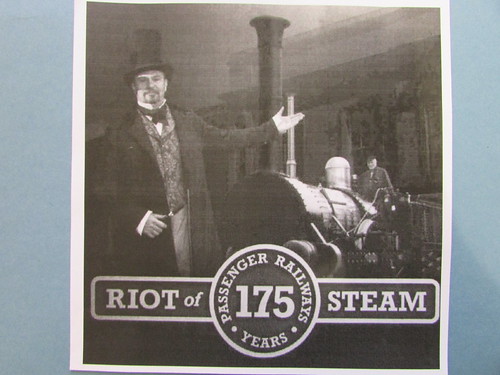
In preparing the post A Personal History of the Museum of Science and Industry recently, I discovered that, whilst my pictures of the 'Riot of Steam' event appear on the internet here, there was no report in this blog. Back in 2005, I wrote a short article about the event which appeared in 'Lionsheart', the newsletter of the Old Locomotive Committee, when I served as the editor. That article appears below.
On the 15th September 1830, the Liverpool and Manchester Railway commenced passenger operation. 175 years later, the original Manchester terminus in Liverpool Road forms part of the Museum of Science and Industry. To celebrate, the museum staged a four day gala on 15th, 16th, 17th and 18th September 2005.
If you missed it, you missed an excellent event. Well, maybe you can catch the 200th anniversary?
The working replicas of ‘Rocket’, ‘Sans Pareil’ and ‘Novelty’ were on hand, supported by the mainstay of museum steam operations, the ‘Planet’ replica. Twice a day, a cavalcade of these four locomotives was held, with an excellent and informative commentary given by Michael Bailey. For the rest of each day, ‘Rocket’, ‘Sans Pareil’ and ‘Planet’ alternated in giving passenger rides, each with its own reproduction coach (or, in the case of ‘Planet’, two coaches).
It’s hard to comprehend just how much organisation was needed to bring the whole gala together. Everybody at the museum is to be congratulated for their imagination is making it happen, providing the finance, and then providing the staff (paid and volunteer) to run the event over four days.
Particularly noteworthy was the appearance of ‘Novelty’, which lives in Sweden (Ericsson, the designer, was a Swede). Although the museum in Manchester has a non-working replica of ‘Novelty’, there is no substitute for a working locomotive (as we have commented regarding ‘Lion’ a few times). Interestingly, just as occurred at the original Rainhill trials, ‘Novelty’ was a firm favourite with the crowds. Something to do with her diminutive size and the way she dashed about. The first day of the gala was also rather wet, again, like the original Rainhill trials, I believe. ‘Novelty’ has now gone back to Sweden so who knows when there will be such a special meeting of replicas again?
Your Editor was present on each of the four days, along with OLCO member John Archer. Jan managed to drive and fire all the locomotives.
‘Lion’ was the only ‘original’ locomotive present representing the 1830s and, when not wet, Liverpool Museum allowed her to be positioned outside to provide better photographic opportunities. Charles Taylor Nobbs and John Brandrick shared the task of telling the visitors a little of the background of this remarkable survivor.
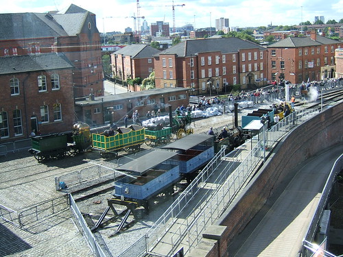
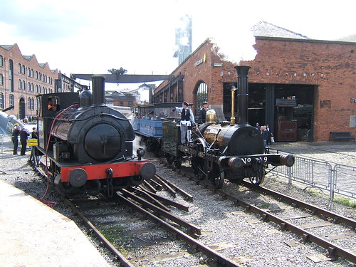
 High-level view of the main 'Riot of Steam' site with (L-R) 'Lion', 'Sans Parel', 'Planet', 'Rocket' and 'Novelty'.
The Liverpool Road Station Site
The first main-line railway in the world was the Liverpool and Manchester Railway, opened in 1830. The Manchester terminus was situated in Liverpool Road and the immediate success of the Liverpool & Manchester Railway resulted in passenger traffic outgrowing the site by 1844, moving to a larger station at Manchester Victoria which offered interchange facilities with other railways which were springing up. The original Liverpool Road site was retained as a Goods Depot which remained in use until 1975. There's a brief history of the site on the excellent 'Disused Stations' site here. The group of buildings and structures which survive offer a remarkable insight into the start of the Railway Age. The term "World Heritage Site" has often been used in describing the area but, tragically, it was not formally so designated and relied on the protection offered, latterly, by the Planning (Listed Buildings and Conservation Areas) Act 1990.
A Science Museum for Manchester
In the 1960s, there was widespread support or the idea of creating a science and technology museum in Manchester and Dr. Richard Hills M.B.E. was involved in the creation of the North Western Museum of Science and Industry, becoming a Curator/Director in 1965. The museum found temporary accommodation in 1967 at 97 Grosvenor Street which had been purchased for redevelopment by the University of Manchester Institute of Science and Technology (UMIST) but the larger objects being acquired by Dr. Hills for the museum had to be dismantled and placed in store until a permanent home could be found.
The Liverpool Road Station Society
A group of mainly local people formed the Liverpool Road Station Society and adopted these aims in 1979:-
The preservation and restoration to its original condition of Liverpool Road Railway Station in the City of Manchester as a place of historical interest with the outbuildings and appurtenances thereto belonging in such manner as shall be thought fit and in furtherance of these objects but not further or otherwise the Society shall have the following powers: To promote public interest in the Society's celebration of the 150th anniversary of the inauguration in 1830 of of the Liverpool and Manchester Railway and for celebrating of the anniversary in succeeding years.
Two aims converge
Greater Manchester Council eventually purchased the Liverpool Road site to provide a permanent home for the Science Museum and this allowed the Liverpool Road Station Society to organise a gala at the site in 1980, the same year that a locomotive cavalcade, 'Rocket 150', was held at Rainhill to celebrate the 150th anniversary of "Rocket's" success at the Rainhill Trials. There's an interesting piece on the acquisition of the Liverpool Road site in the blog of the Centre for the History of Science, Technology & Medicine here.
The Museum of Science and Industry
The Greater Manchester Museum of Science and Industry opened to the public on 15th September 1983. In 1985 the 'Friends of the Greater Manchester Museum of Science and Industry' charity replaced the 'Liverpool Road Station Society' to both continue its work in preserving the railway aspects of the site and also provide volunteers to assist the professional staff in the various museum galleries. Also in 1985, the museum took over the museum established in the former Lower Campfield Market which became the Air and Space Hall.
A short demonstration railway line was created through the museum yard and the Friends operated steam trains on Saturdays, Sundays and Bank Holidays, giving the public round trips from a station near Lower Byrom Street to the museum railway gates adjacent to Water Street. From here, the original connection to the main line was retained, allowing occasional visiting locomotives. The site had two resident locomotives - 'Agecroft No. 3', an RSH 0-4-0ST and 'Lord Ashfield', a Barclay six-coupled Fireless Steam. Passengers were carried in a pair of 4-wheel vehicles built to resemble typical 1830 coaches which were roofed but open-sided. A modest charge was collected by the Friends with the ambitious aim of funding a working replica of an 1830-era locomotive.
At that time, the museum itself operated as a charitable trust under the name 'The Greater Manchester Museum of Science and industry' (sometimes referred to simply as 'GMMSI') which was also its 'working name'. However, the Greater Manchester County Council was abolished on 31st March 1986 so, later, the 'working name' was changed to the 'Museum of Science and Industry in Manchester' ('MSIM') and, similarly, the Friends Organisation became known as 'Friends of the Museum of Science and Industry in Manchester' with the aim of "supporting the Museum of Science and Industry in Manchester by providing volunteers and financial donations". At that time, all working volunteers were required to be members of the Friends organisation. At some point, I think the museum became known as 'Manchester Museum of Science & Industry' ('MMSI')
The visit of 'Lion'
In the post Lion I described how I became involved with the locomotive 'Lion' during her tour in 1988. As a result, I accompanied 'Lion' to Manchester for a series of very successful steamings in 1988.
Jan and the Museum of Science and History
I found the volunteers at Manchester very welcoming. I shared their affection for the unique location and became a member of the Friends, beginning a long career as a working volunteer on the museum's steam railway. I've been a witness to the various changes at the museum since 1988 but not, I'm afraid, an assiduous chronicler. I didn't become a 'blogger' until the end of 2006 (with a tentative initial post titled In the beginning .... There are a number of posts describing my involvement with the museum both before and after that date but it is a very patchy record I'm afraid. You can find them all by selecting the label 'MOSI', clicking here or select individual posts from the list in the section Related posts on this website below.
As a working volunteer at the museum, I was involved with the operation of the steam train rides, progressing through the ranks of guard, shunter, fireman, driver and operating officer. At first, we used the locomotives 'Agecroft No. 3' and 'Lord Ashfield'. From time-to-time there were other visiting industrial locomotives. I was involved in arranging the visit of the 0-6-0 well tank 'Bellerophon' dating from 1874 and was appointed "owner's representative" during the visit. Because of my involvement with 'Lion', I'd also become a working volunteer at Birmingham Railway Museum (there's a brief description here) so I was gaining practical experience at two, albeit short, railways. I'm uncertain about the chronology, but I was delighted when Manchester obtained permission to run the regular trains beyond the museum railway gates. The extended running line took passengers across the Water Street bridge, the listed Irwell Bridge built by the Stephensons in 1830 and into Salford, stopping at a second set of gates beyond which we had a tantalising view of the connection to the parallel main line. On the extension, we could watch the passing trains and they could watch us. Waving and whistling was usual. Further changes to the railway were to follow.
The museum and the 'Planet' replica
As early as 1984, Doctor Richard Hills, talking about the replica 1830 coaches, said "One day, if finances allow, the dream might be realised of building a replica locomotive of the same period to go with the coaches". Led by Michael Bailey, and with additional sponsorship from British Engine Insurance, the Friends organisation succeeded in designing and building a working replica of the 1830 'Planet' locomotive. The replica was inaugurated in 1992. I participated in 'trials' carried out by 'Planet' at two preserved railways - the Great Central Railway and the East Lancashire Railway. After the excitement of the 'trials', 'Planet' settled into the role of bearing the brunt of operating the regular passenger rides. There's a short review of the history of the replica in the post from 2013 here.
Changing times
The museum continued to develop. The regular use of 'Planet' and the extension of the running line over the Irwell Bridge brought increased interest in the railway but, sadly, when heavy repairs to both 'Agecroft No. 3' and 'Lord Ashfield' were required, funds could not be found for either. I regretted this: 'Agecroft No. 3' was the first locomotive I drove on a regular basis and the use of a fireless steam locomotive on a passenger service was unusual, if not unique.
During the 1990s, the museum seemed to lose its pride in its local connections and a re-branding exercise replaced the old-fashioned 'MSIM' (or was it 'MMSI'?) with the inelegant 'MOSI' - 'Museum Of Science & Industry'. Ostensibly to improve site car parking arrangements, some time in the 1990s, the original platform near Lower Byrom Street was abandoned and a new rather inconvenient platform substituted further down the site. At some stage, the shorter run was more than compensated by the laying of a new line across the top of the Colonnade which joined the original line at the Irwell Bridge, forming a 'Y' shaped route and adding interest for the public in being able to watch the fireman operate the ground frame which controlled the junction points.
'Riot of Steam'
In 2005, the Museum improved the railway facilities by constructing a loop and siding in the vicinity of the 1830 Warehouse, in time to mount a major event called 'Riot of Steam' to commemorate the 175th anniversary of the opening of the Liverpool and Manchester Railway. I enjoyed this event, managing to get brief periods driving on the visiting 'Rocket', 'Sans Pareil' and 'Novelty' replicas, in addition to a 'turn' on 'Planet'. The locomotive 'Lion' was in store in the Power Hall at the time (in non-steamable condition) and, with special permission from the owners Liverpool Museums, was dragged into the sunlight. Unfortunately, the event was not a financial success. Remarkably, 'Riot of Steam' has failed to provoke its own blog post here (as yet) but there is a collection of my pictures called Liverpool & Manchester 175th.
Transport Festival, August 2009
The museum re-instated the running line to its original length by using the remaining siding adjacent to the Power Hall (with the all-important inspection pit) as the new running line and providing a new single platform, ready for a nine-day Transport Festival hosted by the museum in August 2009, the last three days of which carried the sub-title the 'Great Garratt Gathering'. My report is here.
Liverpool & Manchester 180th Celebrations
In September 2010 the 180th anniversary of the opening of the Liverpool and Manchester Railway was celebrated at various locations. At the museum, the 'Planet' replica was joined by the 'Rocket' replica (with its own train). As well as working on 'Planet', I was able to renew my acquaintance with 'Rocket'.
More changing times
Although 'Agecroft No. 3' had been transferred to Swindon Museum, with renewed optimism sister engine 'Agecroft No. 1' was acquired (in kit form) and, with support from the Friends, was restored and returned to service in 2011. The museum ran 'Thomas the Tank' events in 2011 and 2012.
MOSI and the Science Museum Group
Amidst increasing austerity, MOSI became part of the Science Museum Group in February 2012. This did not end the financial problems and, in 2013 the Director of Science Museum Group Ian Blatchford said that the further cut in funding proposed by the government would result in one of the northern museums closing, as I reported here. My report also discussed the threat to the museum's extended demonstration line posed by Network Rail's Ordsall Chord scheme. In my later report here in October 2013, I reported that the threat of museum closure had abated, but that a number of paid staff had lost their jobs and that, although the Museum had formally registered objections to the Network Rail proposals, that threat was undiminished.
Happy Birthday 'Planet'
In 2013, the 'Planet' replica was 21 years old and, amid the gathering gloom, a party was held at the museum on 27th November 2013 (report here). When I later heard that the museum had withdrawn their formal objections to the Network Rail plans in return for financial compensation, I think I despaired and subsequently stopped volunteering in circumstances that I would not have chosen.
Spot the difference
Clearly, a little more rebranding was called for. The unloved 'Museum Of Science & Industry' was swept away.
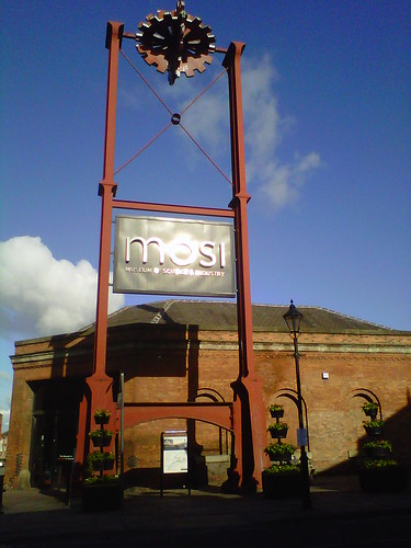
Museum of Science & Industry: The 'Ferranti Tower' in 2012.
The altogether more accessible form 'Museum of Science + Industry' came into use. The '+' sign presumably represents the 'science' part of the brief. Visible on the picture (but not available on a simple 'QWERTY' keyboard, I'm afraid) is the hexagon and circle placed co-axially with the '+' sign. I assume the hexagon and circle form a 'nut' representing the 'industry' side of the brief.
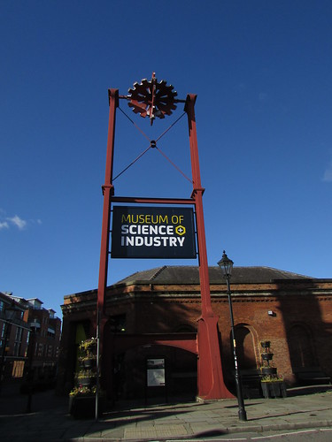
Museum of Science + Industry: The 'Ferranti Tower' in 2016.
Demise of the Friends
The 'Museum of Science + Industry', of course, carries on as part of the Science Museum Group but the museum which the Friends organisation was set up to help no longer exists so the Friends organisation is now disbanded after some 31 years and has disbursed its remaining funds to the 'Museum of Science + Industry' to be used on a number of nominated projects, after which it will be removed from the charities register and will cease to exist. Although the 'Friends' are no more, the Museum is seeking 'Volunteers' - more information here. As far as the railway operation is concerned, there is a role 'Trainee Railway Fireman', described here although I believe paid staff are also used on the operation which still intends to offer passenger rides. The railway 'extension' and the line over the colonnade are no more. The demonsration line is now truncated at the Water Street Railway gate, exactly as it was back in 1988 when I became a Friend.
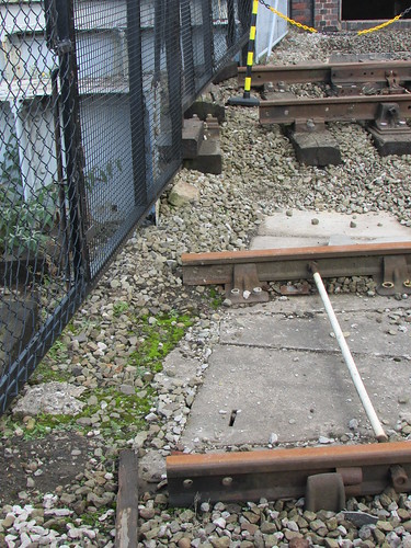
Museum of Science + Industry: Disconnected tracks at the gates of the Museum.
Commemorating the contribution of the Friends
I received an invitation to attend the unveiling of a commemorative plaque in honour of the Friends of the Museum on 19th October 2016. I attended the well-patronised event, specifically hoping to see some of the many railway operating volunteers I'd enjoyed working with over more than a quarter of a century. I think I counted four. The plaque reads:-
Friends of the Museum of Science and Industry in Manchester 1983-2015
The museum gratefully acknowledges the time, work and fundraising of the many members of the Friends organisation. Their tireless support and dedication helped us achieve our high reputation for learning and enjoyment.
My pictures of the event are here.
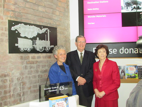
Museum of Science + Industry: Commemorate plaque and (L-R) Sally MacDonald (Museum Director), Michael Bailey, Dame Mary Archer DBE (Chairman of the Board of Trustees).
Related posts on other websites
Liverpool Road (Transport Heritage site)
Liverpool Road (Wikipedia)
Related posts on this website
Dates are original posting dates, not dates of events described.
'Single-Wheeler' locomotives 10-Nov-2015
Driving the 'Planet' replica 11-Sep-2015
Happy Birthday 'Planet'! 29-Nov-2013
'Planet' in Perspective 12-Nov-2013
'Planet' at MOSI - The First 21 Years 21-Oct-2013
Another Saturday in Manchester 12-Oct-2013
The Planet Replica 10-Oct-2013
Manchester Mini Maker Faire 2013 13-Aug-2013
A Busy Week 5-Aug-2013
A Saturday in Manchester 11-Jun-2013
Easter Week at the Museum of Science and Industry 9-Apr-2013
Saturday Steam 4-Mar-2013
Santa Specials - 2012 17-Dec-2012
Day out with Thomas at MOSI 31-Aug-2012
MOSI Mini Maker Faire 15-Aug-2012
Agecroft at MOSI 3-Jan-2012
'Thomas' visits MOSI 4-Sep-2011
Agecroft No. 1 2-Jun-2011
Liverpool & Manchester 180th Celebrations 30-Sep-2010
Beyer Peacock, Gorton 28-Sep-2010
Transport Festival, August 2009 16-Aug-2009
New Platform at MOSI 30-Jun-2009
Dalek Invasion in Manchester 26-Aug-2007
Museum of Science and Industry in Manchester 26-Aug-2007
'Planet' locomotive in Operation 14-Apr-2007
My pictures
All my albums around the museum are here.
[L&M 180th Celebrations added 29-Oct-2016]
Introduction
This is not a comprehensive review of British locomotive designs with just one driven axle but rather a gentle ramble around some of the candidates.
In a steam engine, steam is used to push a piston (connected to a piston rod) up and down a cylinder. The reciprocating motion of the piston rod is used to rotate an axle via a connecting rod. The axle, in turn, drives a load. Many early stationary engines worked like this without refinements.
But when it comes to locomotives, you really need two cylinders set to provide power at different 'angles' to get over the problems of starting. Early locomotives had two 'driving wheels' connected to the driven axle producing what's often called a 'Single Wheeler' (they would be more accurately described as 'Single Driving Axle' but I suppose since you can only usually see one wheel at a time, 'Single Wheeler' stuck). It's necessary to provide at least one more axle provided with non-powered 'carrying wheels' to make a practical locomotive - a rectangular vehicle with a wheel near each corner.
The 'Rocket' class
The first main-line passenger railway in the world was the Liverpool and Manchester Railway. The events leading up to the building of that line, including the Rainhill Trials (the competition held in 1829 to determine whether locomotive engines could provide the motive power, rather than using stationary engines and cable haulage), are briefly described in the post Early Locomotive Design.
The Stephensons (father George and son Robert) applied all the knowledge acquired building earlier locomotives for colliery haulage in producing 'Rocket', their entry for the Rainhill Trials. Their design placed the driving axle at the front and the carrying axle beneath the footplate which, in Whyte Notation we now call an '0-2-2'. The simplicity of this layout, combined with other sound ideas, particularly the multi-tubular boiler, gave the Stephensons victory in the Trials and the order to provide the motive power for the the Liverpool and Manchester Railway.
In 1830, Stephenson's built seven more of the 'Rocket' class locomotives ('Meteor', 'Comet', 'Arrow', 'Dart', 'Phoenix', 'North Star' and 'Northumbrian') for the Liverpool and Manchester Railway. Various alterations were made - larger cylinders, larger boiler diameter. The water-jacketed firebox was made larger and better integrated with the boiler barrel than in 'Rocket'. Some of these had a recognisable smokebox ('Rocket' had only a large 'elbow' to collect the hot gases from the fire tubes and divert them up the chimney). The inclined cylinders of 'Rocket' were changed for virtually horizontal cylinders, partly to reduce the "hammerblow" effect on the notoriously weak rails of the time.
The historical importance of 'Rocket' means that a number of working and non-working replicas have been built over the years, including the 1979 working replica, now held by the National Railway Museum.
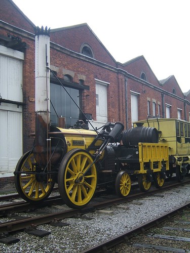
The 1979 working replica of 'Rocket' in Manchester to celebrate the 180th birthday of the Liverpool & Manchester Railway.
The 'Planet' class
The pace of development was remarkable. The innovative 'Planet' design - almost as revolutionary as 'Rocket' had been - was also introduced in 1830. The cylinders were changed from 'outside' to 'inside' and placed in the base of the smokebox to reduce condensation losses, producing a '2-2-0' wheel arrangement. The disadvantage of this change was the need to provide a double-crank driving axle for the connecting rods to turn. With the production techniques of the day, broken crank axles were a risk so 'Planet' had both outside frames and inside frames to provide better support to the crank axle. Before the end of 1830, three more 'Planet' class locomotives had been built - 'Majestic', 'Mercury' and 'Mars'.
In 1831, more 'Planet' class were delivered to the Liverpool and Manchester Railway - 'Jupiter', 'Saturn', 'Sun', 'Venus', 'Vulcan', 'Etna', 'Fury' and 'Victory'. 'Vulcan' and 'Fury' were actually built by Fenton, Murray and Company to the Stephensons' design.
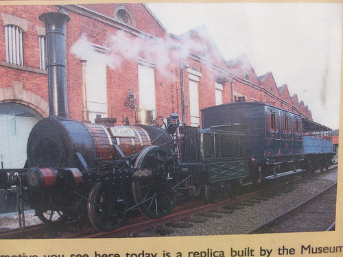
The significance of the 'Planet' design led the then Museum of Science and Industry in Manchester (now Museum of Science and Industry and part of the Science Museum Group) to construct a working replica of 'Planet' which was commissioned in 1992. There are a number of posts in this blog which discuss the 'Planet' replica (or the design of the original locomotive), in the section about the Museum of Science and Industry here.
 The 'Planet' replica.
Limitation of the 'Single-Wheeler' design
As the torque applied at the rail-wheel interface is increased, any locomotive will eventually slip, at a point partly determined by the weight carried by the driving wheels (the 'adhesive weight') and the condition of the rail head. In any 'Single-Wheeler', 'adhesive weight' is less than the total locomotive weight because some weight is taken by the non-powered carrying axle (or axles). 'Adhesion' is briefly discussed in the post Driving the 'Planet' replica.
Although the 'single-wheeler' 'Planet' class excelled on fast passenger trains, many of the earlier designs for collieries had made all the locomotives weight adhesive, either by having four equal-sized wheels with the wheels on each side interconnected by coupling rods (as in 'Locomotion') or by arranging gearing to drive all wheels. At the Rainhill Trials 'Sans Pareil', the only serious competitor to 'Rocket', had four equal-sized wheels with the wheels on each side interconnected by coupling rods (there are pictures of the 'Sans Pareil' replica in the album Liverpool & Manchester 175th).
In 1831, the Stephensons produced a 'modified Planet' with four equal-sized wheels interconnected on each side by coupling rods, providing better adhesion for hauling goods or assisting trains up the inclines. That year, 'Samson' and 'Goliath' were produced, with more to follow in later years.
 Elevation and Plan of 'Samson' class (from a drawing originally published in "The Engineer").
There's a little more on the 'Samson' class in the post 'Planet' in Perspective.
'The Samson Project' is a modern initiative which hopes to build a working replica of this class either as an '0-4-0' or the later '0-4-2' variant.
So why did the Stephensons stay with the 'single-wheeler' design for passenger engines? The production limitations of the time meant that very close dimensional tolerances could not be achieved, resulting in increased 'stiffness' and friction when coupling rods were provided. The reputation of the 'Single-Wheeler' for free-running meant that designers continued to use this format until the end of the nineteenth century.
The 'Patentee' type (and its freight derivative)
Stephenson's continued to develop larger, more powerful engines retaining the single driving axle for passenger trains. The 'Patentee' class adopted an additional pair of carrying wheels giving a '2-2-2' wheel arrangement. The freight versions of the 'Patentee' were usually '0-4-2'. The extra pair of wheels improved the ride, compared with four-wheeled locomotives. The '0-4-2' arrangement lasted for some time and was used by other manufacturers (such as Todd, Kitson and Laird who produced 'Lion'. There are a number of posts on 'Lion', its 'supporters' club' The Old Locomotive Committee and live-steam models of 'Lion' here).
Large 'Single-wheelers'
The top speed of a locomotive could be increased either by making the piston speed higher or by using a larger driving wheel. In the early days, the strength limitations of available materials meant that using larger driving wheels was the better option, although this made locomotives more prone to slipping.
Some designers were tempted to take this business of large driving wheels for higher speeds rather to extremes but, in the hands of a skillful driver, it's remarkable what feats were achieved. A selection of designs are listed below.
'Firefly' class
In 1840, Daniel Gooch introduced onto Brunel's Great Western Railway the 'Firefly' class of broad gauge '2-2-2' with driving wheels just over 7 feet in diameter. This very successful design ultimately extended to 62 locomotives. There's a description on Wikipedia here.
There is a full-size working replica of 'Firefly' described on The Broad Gauge Society site here. This replica is at Didcot Railway Centre, where it is occasionally steamed on a special broad gauge railway described here.
 'Firefly is depicted on a medal commemorating the 150th Anniversary of the GWR.
'Iron Duke' class
'Great Western' followed in 1846, also originally built as a '2-2-2' but with 8 feet diameter driving wheels. Upon breaking its leading axle, the locomotive was rebuilt as a 4-2-2 (with the leading carrying wheels fixed were in the frames, not arranged as a bogie), then becoming one of the fast, capable 'Iron Duke' class, described on 'Wikipedia' here.
The importance of 'Iron Duke' induced the Science Museum to produce a full-size working replica in 1981, in time for GWR 150th Anniversary which was celebrated in 1985. This replica is now held by the National Railway Museum and there's a little more here. There's more about the replica 'Iron Duke' on The Broad Gauge Society site here.
 The replica 'Iron Duke' on display at Toddington (Photo: Rob Speare).
'Columbine' class
In 1845, Alexander Allen built 'Columbine' at Crewe for the Grand Junction Railway (which became part of the London & North Western Railway the following year). This '2-2-2' had outside cylinders and many features perpetuated by Crewe for many years. The locomotive was not finally withdrawn until 1902 and is now part of the 'National Collection', displayed in LNWR "blackberry black' lined livery. There's a brief entry on the National Railway Museum site here. The 'The Victorian Web' has a nice collection of photographs here (although the text is a little suspect).
 'Columbine' on display in York (Photo: NRM).
I first saw this locomotive over 50 years ago in the Paint Shop at Crewe, along with '0-4-2' 'Lion'.
'Crampton' designs and 'Cornwall'
In 1846, a design by Crampton featured a low-slung boiler for stability and a single driving axle placed well back, allowing fairly large wheels for speed. The design became more popular in France and Germany although a number were operated in Britain. The most remarkable example in this country was the 6-2-0 'Liverpool' with 8 foot diameter driving wheels built in 1848 for the London & North Western Railway. The 'Cramptons' are described on Wikipedia here.
In 1847, Francis Trevithick produced 'Cornwall' for the London & North Western Railway as a '4-2-2' with 8 foot 6 inch diameter driving wheels, intended as an 'improved Crampton'. To keep the centre of gravity low, the unusual boiler was placed below the driving axle! In 1858, Ramsbotton carried out a major rebuild as a '2-2-2' retaining the large driving wheels but with the driving axle conventionally passing underneath the boiler, as described on Wikipedia here.
 'Cornwall' on display at Shildon (Photo: James E. Petts via Creative Commons).
When I became a volunteer at Birmingham Railway Museum in the late 1980s, 'Cornwall' was in store in the shed. I sat on the footplate many times imagining the locomotive in steam.
'Stirling Singles'
On the Great Northern Railway in 1870, Patrick Stirling introduced a very successful class of 4-2-2 'Singles', finally totalling 53 locomotives, with a driving wheel diameter of 8 foot 1 inch. There's a short 'Wikipedia article here.

Stirling 4-2-2 displayed at Doncaster in 2003 (Photo: Our Phellap).
Caledonian Railway 'Single' 123
The most famous of the Caledonian Railway 'Singles' is the preserved '123' which participated in the Race to the North. Dugald Drummond adopted 7 foot driving wheels for the 123 built by Neilson in 1886 (Neilson later became part of North British Locomotive Company Limited and there's a short history here).
 Caledonian '123' (Photo: Glasgow Museums).
Midland Railway 'Singles'
As late as 1896, Samuel Waite Johnson produced the '115' class for the Midland Railway with driving wheels around 7 foot 9.5 inches diameter. They could certainly 'run' and the appearance of the single driving wheel at speed (or their tendency to slip) suggested their nickname 'Spinner'. There's a Wikipedia article here).

'Spinner' at Rainhill in 1980 (Photo: Antony Guppy).
An unusual 'Single Wheeler'
Aveling Porter are best known for their road rollers and traction engines but they did manufacture some railway locomotives for shunting purposes. Most of these were four-coupled but there is a preserved '2-2-0' Well Tank built in 1926 named 'The Blue Circle' which manages with one cylinder and a flywheel. There's some information about this remarkable survivor on the Bluebell Railway website here, and there's a very short post in my blog here which links to an album of pictures. This locomotive has also carried the name 'Fergus', commemorating its appearance in 'Thomas and Friends'.
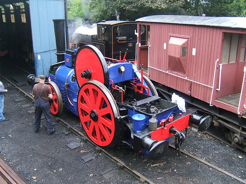 'Blue Circle' being prepared for service by Mick on the Battlefield Line in 2007.
The Large 'Single-wheeler' era ends
With the improvement in materials and production technology, it became possible to permit higher piston speeds with safety and the need for very large driving wheels declined. In this country, a driving wheel around 6 foot 8.5 inches diameter became the norm for fast running. Increasing train loads meant that a single driving axle was inadequate and 2, 3 or 4 axles would be coupled together. Again, the improvements in production techniques meant that the power losses originally associated with coupled wheels were acceptable.
Single Wheelers I've driven
'Rocket' replica
My first involvement with the 'Rocket' replica was at a Gala at Birmingham Railway Museum (late 1980s, I think) when I spent some time on the footplate with Ray Towell from the National Railway Museum. 'Rocket' visited the Museum of Science and Industry in Manchester (now Museum of Science and Industry) in 2005 and again in 2010 (celebrating 175 and 180 years, respectively, of the Liverpool and Manchester Railway). I managed to do a bit of driving and firing on both occasions. There's a little more about these events (with links to pictures) here.
'Planet' replica
When the 'Planet' replica was being built at the Museum of Science and Industry in Manchester, I was already a volunteer driver there. I did a few odd jobs during erection. I remember balancing on top of the boiler as the overhead crane lowered the tall chimney which I had to guide into its mounting flange on the smokebox.
In October 1992, there were lots of special steamings following the official launch. The locomotive went out on two sets of 'Trials', firstly at the Great Central Railway (at Loughborough) then to the East Lancashire Railway (at Bury). I was involved on both these visits and there's some information in the post The Planet Replica. We also made a visit to the National Railway Museum (at York) for a Gala, where we ran 'Planet' up and down on a special demonstration line without conveying passengers but I'm not sure of the date. 'Planet' did make a number of subsequent visits to other sites, although I wasn't personally involved in these. I was involved in driving 'Planet' at Manchester during the 175 and 180 year celebrations of the opening of the Liverpool and Manchester Railway and during the Transport Festival (and Great Garratt Gathering) in 2009. There's a little about the 175 and 180 year events here and a short report on the Transport Festival here.
I continued to drive in Manchester on the regular weekend service and a few special events (I well remember the Dalek Invasion in Manchester) until some time after 'Planet's' 21st birthday (described here).
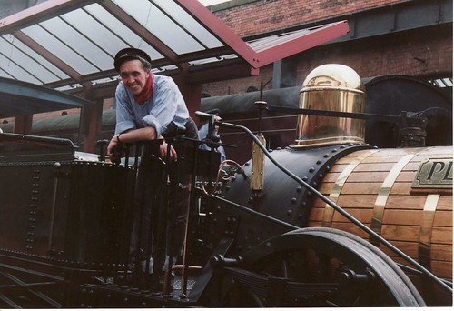 'Planet' replica (and a much younger Jan) at the original platform at Manchester some time in 1992-1993 (Photo: L. Walker, Wigan).
'Iron Duke' replica
When I was at York with the 'Planet' replica (mentioned above) the 'Rocket' replica was giving passenger rides on the standard gauge demonstration line and the 'Iron Duke' was giving passenger rides on the broad gauge demonstration line. They offered me a drive on either (not both) at the end of the public service. I elected for 'Iron Duke' which remains the only 7-foot gauge locomotive I've driven, although I've driven 5-foot 6-inch gauge in India (see the post My First Trip to India (continued)) and 5-foot gauge in Ukraine (see the post Ukraine 2005).
'The Blue Circle'
Mick, the owner of 'Blue Circle' has always encouraged my interest in his unusual motive power and one day he let me fire and drive up and down at Shackerstone on the Battlefield Line. It was an interesting experience!
 'Blue Circle' at Shackerstone in 2010: Driver's view.
Related articles on other sites
George Stephenson.
Robert Stephenson.
Related articles on this web site
Early Locomotive Design.
The Planet Replica.
'Planet' in Perspective.
Liverpool & Manchester 180th Celebrations.
'Planet' at MOSI - The First 21 Years.
Driving the 'Planet' replica.
Aveling & Porter Locomotive.
My pictures
Liverpool & Manchester 175th.
Liverpool & Manchester 180th.
In the post 'Planet' at MOSI - The First 21 Years, I celebrated the 21st Birthday of the 'Planet' replica in October 2013.
When I was driving the 'Planet' replica, people sometimes asked if it was different from driving 'modern' steam locomotives. The answer is "not very, apart from the the fact she's a 'single wheeler', has a rather special braking system and an unusual method of reversing" ('Planet', like its immediate predecessor 'Rocket' has Slip Eccentric reversing). The basic principles of the steam locomotive haven't changed very much since the early days, although the appearance of the 'Planet' replica is very different from modern steam locomotives.

The 'Planet' replica being prepared for service with MOSI volunteer
Bev on the right.
I've already written about driving another early locomotive design in the post Driving 'Lion'. 'Lion' was built just eight years after the original 'Planet' and so there are many similarities, although 'Lion' incorporates Gab motion for reversing.
Adhesion
'Planet' has just one pair of driving wheels, which share the total weight of the locomotive with the leading pair of carrying wheels. Using Whyte's Notation, the arrangement is said to be a '2-2-0'. The total weight on the driving wheels is the 'adhesive weight'. With a single driving axle, not all of the locomotive weight can be adhesive. In the case of the original 'Planet' there was about 5 tons on the driving wheels, with about 3 tons on the carrying wheels. When the driver wants to get the train in motion, steam is used to generate sufficient torque at the driving wheels to move the load. But, if the torque applied to the driven wheels exceeds a critical value (related to the coefficient of friction between the wheels and the rails), the driving wheels slip on the rails and the train does not move.
This was more of a problem with goods trains, which tended to be heavier, so it was desirable to make all the locomotive weight adhesive to reduce the risk of slipping. On goods engines (then called 'luggage engines') the torque generated on the two driving wheels was shared with a similar pair of wheels linked to the driving wheels with coupling rods, giving a wheel arrangement of '0-4-0'. As the size and weight of locomotives increased, further coupled wheels were often used, although 'single-wheelers' weren't eliminated for some years as they could be free-running and, with large driving wheels, fast.
Because the 'Planet' replica only has one pair of driving wheels, it can be 'light on its feet' and prone to slipping so the driver has to take care when starting not to open the regulator too far.
Braking
In the early days of steam locomotives, effort was concentrated on making machines powerful enough to pull a useful load and braking technology was rather neglected. On both the original 'Planet' and the replica, there are two hand brakes, one on each side of the tender, and these are applied by 'screwing down' the handles which project from the top of the tender. Wooden brake blocks are provided which rub against the tyres of the tender wheels to provide braking. On the original 'Planet' that was it! This arrangement wasn't terribly effective in 1830 (severe braking could set the brake blocks on fire!) and, in the replica, the hand brakes are normally used only as a 'parking brake'.
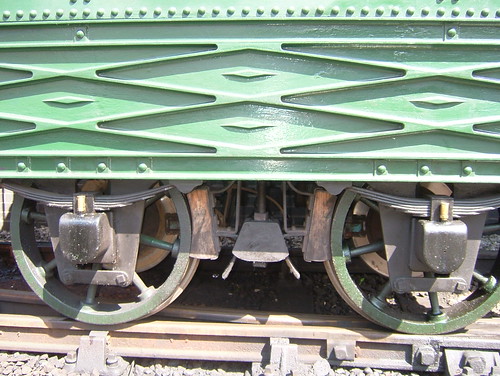
 Left side of replica tender showing the cast decorated panel and wooden brake blocks which are pulled against the tyres of the tender wheels by the screw handbrake to provide braking. Brake discs and calipers for the modern air brakes are visible between the wheel spokes.
To be acceptable for hauling passenger trains today, the 'Planet' replica also has an Air Brake system. This operates a disc brake on the leading axle of the locomotive, disc brakes on both tender axles and the train brakes. The regulator should always be closed before attempting to brake. I talk a bit about braking and the use of the automatic Vacuum Brake here. Air Brakes form another type of automatic braking (which I've not, to date, described). With the withdrawal of steam traction in the U.K., British Railways started to change over from vacuum braking to air braking and the 'Planet' replica has a version of what became the standard British Railways Two-Pipe Air Braking system.
Converting steam into rotary motion
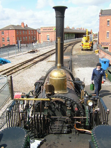
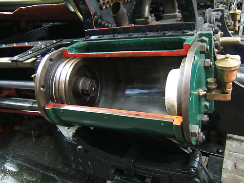
This part of the locomotive has changed little since the early days. The 'Planet' had two horizontal cylinders at the front between the frames. When the regulator is at least partly open, steam flows through the main steam pipe to feed the two cylinders. The principle is simple - the steam under pressure is used to push a piston to the far end of a steam-tight cylinder. The picture below shows a deliberately 'sectioned' cylinder making the construction clearer. The piston is attached to a Piston Rod which sticks out of one end of the cylinder (through a steam-tight piston gland) and it's the motion of the piston rod which allows the cylinder to do useful work.
 'Sectioned' cylinder on Beyer Peacock locomotive 'Pender' on display at MOSI. The piston is shown in its rearmost position in the cylinder and the Piston Rod extends to the left.
As the piston approaches the end of the cylinder, it's necessary to cut off the supply of steam and divert the steam to the other end of the cylinder so as to push the piston back again. This requires a valve in between the steam supply and the cylinder called (logically enough) the Steam Valve. The opening and closing of this valve must be synchronised with the movement of the piston. The two pictures below of the 'Planet' replica give an idea this was engineered in 1830, using complicated iron castings which were at the limit of what was technically possible.
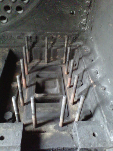
The first picture below is taken inside the smokebox of the 'Planet' replica looking down onto the top of the left hand cylinder with the steam chest removed from the threaded mounting studs so as to show the flat port face area with two rectangular steam ports (connected to each end of the cylinder) and the larger rectangular exhaust port (connected through a passage to the blast pipe).

Top view of cylinder showing the cylinder ports (2 steam, 1 exhaust).
The second picture shows the underside of the steam chest which has been removed in the first picture. The steam chest is complete with the cast rectangular steam valve attached to the valve rod which sticks out of one end of the steam chest (through a steam-tight valve gland). The flat face of the valve bears slides to and fro against the flat port face so this type of valve is called a Slide Valve.
 Steam chest complete with slide valve and valve rod.
The reciprocating motion of the two piston rods is converted to rotary motion of the driving axle by connecting rods linking the end of the pistons which pull and push a double-crank driving axle, as shown in the picture below. Practical locomotives have at least two cylinders and, on a 2-cylinder design, the cranks are set 90 degrees apart so that both cylinders cannot be on dead centre. This means that a locomotive can always be started (using the effort from at least one cylinder), whatever the position of the cranks.
More than a century after the building of the original 'Planet', similar arrangements remained in use. An increasingly common variation was to move the cylinders outside the frames where the connecting rods drove onto crankpins fitted to the driving wheels, but both inside cylinder and outside cylinder designs lasted until the end of steam. Some designs had additional cylinders and a locomotive might have both inside and outside cylinders. As locomotives became larger, slide valves were replaced by balanced slide valves and then piston valves. A variety of other valves (poppet, sleeve) were tried but piston valves emerged as the most practical form of valve. A few attempts were made using quite different techniques, like steam turbines, but double-acting reciprocating cylinder designs remained virtually unchallenged.
Valve Gear
As remarked above, the opening and closing of the steam valve to admit steam from the boiler to either end of the cylinder must be synchronised with the movement of the piston. Since the piston is used to turn the driving axle, if the motion of the steam valve is derived from the turning of the driving axle, the necessary synchronisation is obtained. The motion of the steam valve is derived from the rotation of the driving axle on this design by a special eccentric. A simple eccentric is a type of crank with a small 'throw' - see Wikipedia here. A simple eccentric is fixed to the axle which turns it so as to produce the correct valve events to rotate the driving axle in one direction.
But a locomotive must be able to move in both directions and this was achieved in 'Planet' and other early locomotives by the use of a Slip Eccentric for each cylinder mounted in the middle of the crank axle, as shown in the picture below. A Slip Eccentric is an eccentric which can engage with the crankshaft in two positions where one provides the correct movements of the eccentric rod and the valve rod for clockwise rotation of the driving axle whilst the other position produces anticlockwise rotation of the driving axle. This is achieved by providing lugs or 'dogs' which can engage with one of two mating recesses or pits. A transverse shaft operated from a foot pedal on the footplate is used slide each eccentric across the axle so as to disengage one lug and allow the other lug to engage when the axle has turned so as to bring the other recess in line.
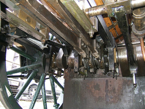 "Planet's" driving axle and eccentrics viewed from below. L-R: RH driving wheel, intermediate axlebox, RH crank driven by (black) connecting rod, inside axlebox, RH eccentric and rod, LH eccentric and rod, inside axlebox, LH crank driven by (black) connecting rod.
Click here for a larger view
So, reversing the locomotive involves disengaging one lug in the slip eccentrics and turning the driving axle until the other lug engages. Achieving this probably provides the biggest challenge to the driver. There are two ways of achieving this changeover:-
1. Turn the driving axle by controlling the valves manually.
2. Perform a 'flying reverse'.
Reversing by controlling the valves manually involves operating the foot pedal to the other position, disengaging both valves from the eccentric rods (by operating the two small valve locking levers mounted on top of the left and right footplate railing) and operating the valves appropriately by hand (using the two curved levers mounted on the boiler backhead facing the driver) so as to move the locomotive. When the eccentrics have re-engaged, the two small valve locking levers are used to re-connect the eccentric rods with the valves, allowing the locomotive to be driven normally.
The 'flying reverse' is potentially simpler but requires careful judgment. This can be used if the locomotive is already in motion in one direction and requires to stop and then re-start in the opposite direction. The driver closes the regulator and uses the brakes so as to stop in the correct position. Before actually stopping, the foot pedal is operated to the other position. If judged correctly, the slip eccentrics will engage for the opposite direction before the locomotive comes to a stand. The 'flying reverse' can also be used if the locomotive is stationary but on a sufficient gradient so that it will roll when the brakes are released.
The view below of the footplate of the 'Planet' replica, shows the location of the controls used by the driver when reversing.

The 'Planet' replica in the Power Hall at MOSI. L-R: Steam chest pressure gauge, valve locking lever (on top of railing), two long curved levers (for manual operation of valves), foot pedal (for reversing), water gauge, regulator, water gauge, blower valve with injector steam cock below, boiler pressure gauge, valve locking lever (on top of railing).
Click here for a larger view
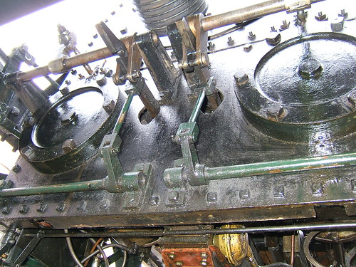
The two valve locking levers and the two long curved levers for the manual operation of the valves connect to the front of the locomotive via a series of rods. The picture below shows the two rocking shafts (top of picture) which operate the valve spindles controlling the valves in the steam chests described above. When the small valve locking levers are engaged, each rocking shaft is driven by the associated eccentric rod. To allow manual operation of the valves, the small valve locking levers disengage the eccentric rods from the rocking shafts by two shafts operating lifting links (near the bottom of the picture, painted green) which disengage each eccentric rod from its valve spindle.
 Looking at the front of the cylinders from underneath the locomotive showing the method of disengaging the valves from the eccentric rods. The cylinder front covers are dummy, made to the diameter of the original 'Planet'. The replica 'Planet' has smaller cylinders because of the increased working pressure (100 p.s.i. compared with 50 p.s.i. in the original).
Click here for a larger view
Development of Valve Gear
Slip eccentric reversing of locomotives did not survive. By providing four fixed eccentrics and eccentric rods, rather than two, the correct valve movements for both directions of movements on two cylinders could be provided. Initially, a mechanism connected to a simple reversing lever on the footplate connected two of the four eccentric rods to the valve spindles. For instance, 'Lion' of 1838 features Gab motion.
But, by 1842, Stephenson's link motion appeared in the U.K. offering not only reversing but variable cut-off allowing steam to be used expansively for greater efficiency. This became the predominant valve gear in the U.K. for many years. Don Ashton's authoritative review of Stephenson Link Motion can be found here,
For comparison with the picture above showing "Planet's" driving axle and eccentrics, the picture below shows "Sapper's" driving axle and eccentrics. "Sapper" is an 0-6-0 'Austerity' tank built more than a century after the original "Planet". Stephenson Link Motion had replaced slip eccentric reversing but otherwise the layout is similar.
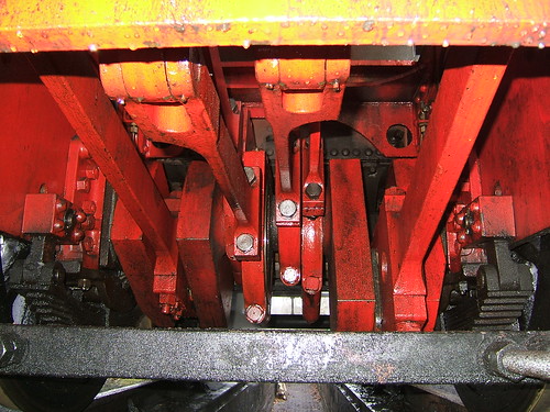 "Sapper's" driving axle and eccentrics viewed from below. L-R: RH axlebox and underhung laminated spring, RH crank driven by (red) connecting rod, RH fore eccentric and rod, RH back eccentric and rod, LH back eccentric and rod, LH fore eccentric and rod, LH crank driven by (red) connecting rod, LH axlebox and underhung laminated spring.
Click here for a larger view
Design issues
In general, materials and manufacturing techniques now are far superior to anything available in 1830. Steel was not available then - wrought iron was the best material but quality was very variable and only limited size sheets were available which required joining by riveting. Cast iron in the complex forms required for cylinders and valve chests was pushing at the limits of the technology available at the time.
The 'Planet' replica incorporates a number of features which were not possible in 1830 (for instance, air brakes, blower, injector, whistle, water gauges, pressure gauges) but that discussion I'll defer to a later article.
Related posts on this website
Early Locomotive Design.
The Planet Replica.
If your interest is broader than just the 'Planet' replica, there's a series of articles describing working on preserved railways and driving various steam locomotives. Most of these articles can be found here
My Pictures of the 'Planet' replica
'Planet'.

The 'Planet' replica at MOSI is 21 this year. The exact date depends upon which particular event you choose as the 'birthday'. I normally use the official launch by the Lord Mayor of Manchester on 2nd October 1992.
The birthday party celebrating 21 years of operation was held at MOSI on 27th November. The guests were Volunteers, Friends of the Museum and people who were involved in the 'Planet' Project and the previous Director of the Museum, Steve Davies - quite a gathering.
Of course, 'Planet' was in steam giving rides. Even at 5.00 p.m. it was already dark.
 Vince and Duncan enjoy a ride behind 'Planet' in the dark.
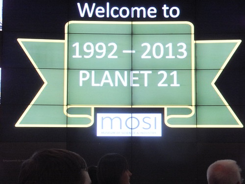
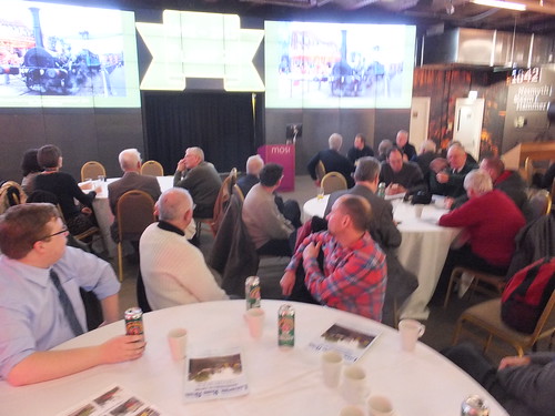
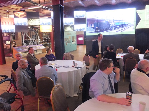
When everyone had admired 'Planet', taken a ride or just enjoyed chatting, the guests moved into the main building. A number of large round tables with chairs had been set up on the ground floor in front of a modern multi-screen video display comprising a central panel of 3 x 3 screens flanked on either side by panels of 4 x 4 screens together with a series of smaller screens forming 'wings'. Beverages were served initially and then a long queue formed where the guests were quickly served a delicious Lancashire Hot Pot.
 In the Dining Area, the 'Big Screens' showed duplicated video images of 'Planet'.
 Another view of the Dining Area showing one of the 'Big Screens' and one 'wing' of smaller screens.
Matthew Jackson has been Railway Officer for six years but, sadly, is shortly leaving. Mike Ward made a presentation to Matthew on behalf of his many friends. The Chairman of the Museum Friends, Mike Crawley, then gave a short address about 'Planet' and the threat to the future of the railway posed by the Ordsall Chord Project (there's more about the Ordsall Chord in my post Another Saturday in Manchester).
The main speaker of the evening was Michael Bailey but, unfortunately, the writer and other guests with long distances to travel were unable to stay for the remainder of the celebrations.
This event concluded 21 years of successful operation of 'Planet'. For more information about 'Planet', see my 'Planet' Loco-profile here which includes a number of 'related post' links to articles describing the original 'Planet' locomotives together with the building and operation of the 'Planet' replica.
My pictures
My rather poor pictures of the'birthday party' are here.
A little background
When the Liverpool and Manchester Railway was being built following authorisation by the Parliamentary Act of 1826, the decision regarding propulsion had not been made. The options were cable haulage, using a series of stationary steam engines along the line, or the use of self-propelled 'locomotive engines'. The Directors of the Liverpool and Manchester Railway decided upon a competition, with a £500 prize to the winner, to find the best steam locomotive design before finally deciding upon the method of traction for their line. In 1929, the Rainhill Trials were held, amid massive public interest, and 'Rocket' was the winner. There's a brief description of this period in the post Early Locomotive Design.

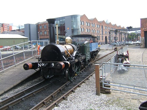
The National Railway Museum 'Rocket' replica.
For the opening of the Liverpool and Manchester Railway, a number of locomotives fairly similar to 'Rocket' were built by the Robert Stephenson works.
Experience with the 'Rocket' class suggested a number of technical improvements which were incorporated in the very successful 'Planet' class. The Stephenson works produced four 'Planet' class locomotives by the end of 1830, with a further four in 1831, supplemented by two very similar locomotives manufactured by Fenton, Murray and Company. The design of the 'Planet' class was so successful that, for a number of years, locomotives were essentially derivatives or enlarged versions of 'Planet'.
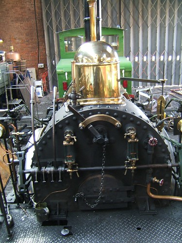
 The 'Planet' replica (with shortened chimney).
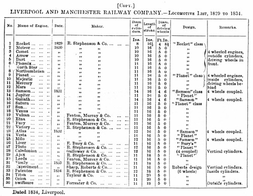
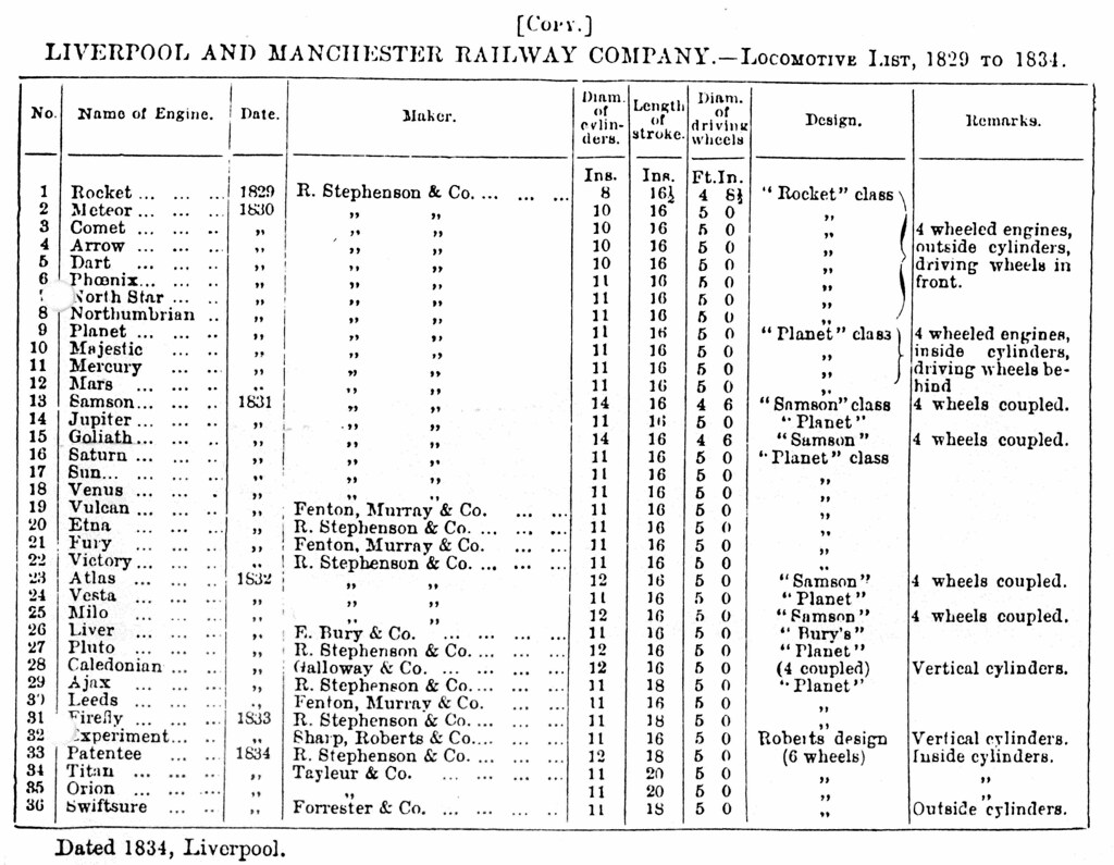
Liverpool & Manchester Railway company - Locomotive List, 1829-1834
 Click here for larger view.
The above list, produced after a few years operation of the Liverpool and Manchester Railway, is worth studying in detail. It is taken from the book by Clement E. Stretton [reference 1]. The success of the railway is clear from the fact that no less than 36 locomotives appear on the list, headed by No. 1 'Rocket', built in 1929.
The 'Rocket' class
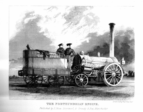
The cylinders on 'Rocket' were 8 inches in diameter, with a 16.5 inch stroke and the driving wheels were 4 feet 8.5 inches diameter. A further seven locomotives (No. 2 - No. 8) were built in 1830 to inaugurate the service. Although the list shows them as 'Rocket' class, there were a number of changes Compared with 'Rocket', the cylinder diameter was increased to 10 inches (on the first four locomotives) and again to 11 inches (on the final three locomotives). There was a small reduction in stroke to 16 inches and the driving wheel diameter was increased to 5 feet. The first four locomotives had a larger number of smaller diameter smoke tubes and a chimney similar to 'Rocket', swelled at the base to join onto the front of the boiler but, thereafter, the chimney was carried on a recognisable 'smokebox'. Note that the cylinders have been lowered from the steeply-inclined position of the original 'Rocket' to an almost-horizontal position to reduce impact on the track. 'Rocket' itself had the same cylinder position modification at some stage. On the last of the 'Rocket' class, No 8 'Northumbrian', illustrated in the Shaw print below, the mature form of the 'Stephensonian' boiler appears with a larger water-jacket firebox integrated with the boiler (which now has 132 smoke tubes of 1 and 5/8 inch diameter).
 Shaw: Plate IV The Northumbrian Engine.
The 'Planet' class
The 'Planet' class quickly followed and the Robert Stephenson and Company works produced the first four class members in 1830 - 'Planet', 'Majestic', 'Mercury' and 'Mars' (No. 9 to No. 12). The 11 inch by 16 inch cylinders of the later 'Rocket' class engines were retained, as were the 5 foot diameter driving wheels but the configuration of the class was completely revised from an 0-2-2 to a 2-2-0, as described in the post The Planet Replica.
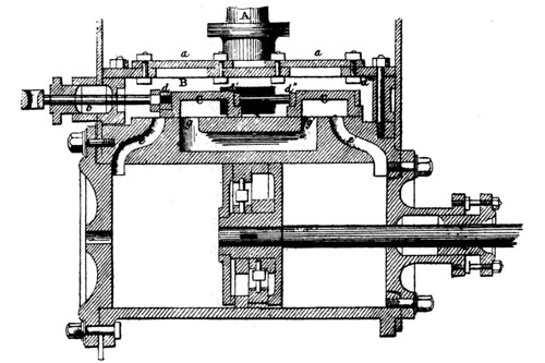
The diagram below shows the design of the cylinders for the 'Planet' class. Note that both front and rear covers were cast separately from the cylinder. Also note that the steam valve was split into two sections. This arrangement created extra wear and was not perpetuated.
 Diagram of 'Planet' class cylinder (from Ahrons book [reference 2], drawing originally published in "The Engineer").
In 1831 the Stephenson works turned out another six 'Planet' engines - 'Jupiter', 'Saturn', 'Sun', 'Venus', 'Etna' and 'Victory'. In the same year Fenton, Murray and Company produced two 'Planet' class locomotives on the recommendation of Robert Stephenson & Co. (using Stephenson drawings), which were given the names 'Vulcan' and 'Fury'. Robert Stephenson & Co. also produced the first 4-coupled engines of the 'Samson' class, described below.
In 1832, another six 'Planet' locomotives were acquired by the Liverpool and Manchester Railway. Robert Stephenson & Co. produced 'Atlas', 'Vesta', Milo, Pluto and 'Ajax', whilst Fenton, Murray and Company built 'Leeds'. Of these six locomotives, only 'Vesta' and 'Leeds' had 11 inch by 16 inch cylinders - 'Atlas', 'Milo' and 'Pluto' had 12 inch by 16 inch cylinders and 'Ajax' was equipped wit 11 inch by 18 inch cylinders! In the same year 'Liver' was supplied by Bury and Galloway & Co. provided 'Caledonian' - something of a 'throwback' with vertical cylinders.
In 1833, Robert Stephenson & Co. supplied another 'Planet' class, 'Firefly', with the 11 inch by 18 inch cylinders which had first appeared on 'Ajax'. But more significant was the supply of a 2-2-2 locomotive - 'Patentee', the first of a new class, described below.
The 'Samson' class
A significant development in 1831 was the emergence of a 4-coupled version of 'Planet', intended for goods and banking duties. Cylinder size was enlarged to 12 x 16 inches. By having four equal-sized wheels and coupling them together, all the weight of the locomotive became adhesive. The crank pins on the trailing wheels were ball joints, to provide flexibility (like 'Rocket') whereas the crank pins on the leading wheels were parallel-sided. The drawing below shows the arrangement. Note that the elevation shows the front of the locomotive to the right, whereas on the plan, the front of the locomotive was on the left.
Elevation and Plan of 'Samson' class (from Ahrons book [reference 2], drawing originally published in "The Engineer").
The 'Patentee' class
Partly to improve riding and partly to facilitate the design of ever-larger locomotives, Robert Stephenson & Co. added a pair of carrying wheels at the rear of the locomotive. In a single-driver (like the 'Planet' class), this produced a 2-2-2, in a four-coupled design (like the 'Samson' class), this produced an 0-4-2. Cylinder size was enlarged to 12 x 18 inches. The design flexibility that this change offered meant that, for some years, locomotive design could be based on 'ringing the changes' on the 'Patentee' configuration.
Related posts in this blog
Early Locomotive Design.
The Planet Replica.
'Planet' at MOSI - The First 21 Years.
Book References
[1] 'The Development of the Locomotive - A Popular History 1803 - 1896' by Clement E. Stretton.
[2] 'The British Steam Railway Locomotive 1825 - 1925' by E. L. Ahrons, reprinted Bracken Books 1987 (ISBN 1 85170 103 6).
[3] 'A Century of Locomotive Building by Robert Stephenson & Co. 1823 - 1923' by J. G. H. Warren, reprinted David & Charles (7153 4378 5).
Introduction
The 'Planet' Replica official "launch" (not sure that's the right word for a locomotive) took place at the Museum of Science and Industry (MOSI) in Manchester on 2nd October 1992. For the first few steamings, 'Planet' conveyed only Invited Guests from the project sponsor, British Engine Insurance, but Public Steamings commenced at the end of October 1992.
The ambition to build a working 'Planet' goes back to at least 1984 when Doctor Richard Hills, talking about the replica 1830 coaches, told 'Railway World' said "One day, if finances allow, the dream might be realised of building a replica locomotive of the same period to go with the coaches".
By the time I became a working volunteer in 1988, the Museum was running steam train rides using steam locomotive 'Agecroft Number 3' or fireless steam locomotive 'Lord Ashfield'. The profits from these rides all went into the 'Planet Fund' and, with the support of British Engine Insurance, completion of the 'Planet' replica was assured.
Designing the Replica
Creating a copy of an 1830 locomotive is an ambitious task, carried out by Michael Bailey, as Planet Project Leader, heading a small design team. Modern Health and Safety requirements meant that the design could not be an accurate copy of the original and various compromises had to be introduced although the design sought to reproduce the appearance and performance of the original.
The original boiler was wrought iron of riveted construction with a working pressure around 50 pounds per square inch. It was decided to substitute a modern welded steel boiler. In the original 'Planet', feed water to the boiler was provided via a crosshead-driven water pump (briefly described in the post The Clack Valve). Since this type of pump can only be used when the locomotive is moving, it was decided to add an injector to the replica (anachronistic, as the injector was not invented until 30 years after 'Planet' was built). To ensure reliable operation of the injector, the working pressure of the replica was raised to 100 p.s.i. The increased steam pressure then determined that the cylinder dimensions be scaled down, to produce a similar tractive effort to the original 'Planet'.
The importance of brake power had not been fully appreciated when the original 'Planet' was built and only handbrakes on the tender were provided. Fitted with wooden brake blocks, they were of limited usefulness. To be acceptable for hauling passenger trains today, the 'Planet' replica was equipped with brakes using the British Rail 2-pipe air brake system and disc brakes (one disc on the driving axle and one on each of the two tender axles).
Building the Replica
The Museum was very different then - the Great Western Warehouse building had a large workshop with an overhead travelling crane. As much as possible of the production was carried out in this workshop by a mixture of paid staff and volunteers but specialist tasks, such as manufacture of castings or building the boiler, were sub-contracted to outside firms.
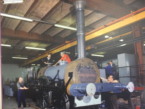
'Planet' was 'erected' on a short length of track in the workshop area. I wasn't much involved in the erection, although I remember balancing precariously on top of the boiler with another volunteer as the overhead crane lifted the chimney, the bottom of which we had to thread into the 'collar' on top of the smokebox.
 'Planet' replica under construction (Photo: MOSI).
Testing the Replica
The 'Planet' team were keen to carry out trials to see just what the locomotive was capable of and I was involved in two sets of early trials - the first at the Great Central Railway, the second at the East Lancashire Railway.
At the Great Central, trials started on 15th February 1993. 'Planet' hauled the two reproduction 1830 coaches and, on at least some trips, a brake van. The leading compartment of the coach next to the locomotive carried a portable air compressor driven from a petrol engine to charge the air brake system. The engine pulled the train from Loughborough to Rothley and then coasted downhill back to Loughborough. I think a speed limit of 15 m.p.h. was imposed. The trials were not without incident. Grease lubrication on the tender axleboxes gave some trouble and required attention. On another run uphill, just before Swithland Reservoir, a welded bracket in the valve gear on one cylinder gave way. Having stopped the train, everybody on the train formed a search party scanning the line we'd just passed over looking for the missing parts. Once these had been retrieved, 'Planet' limped back to Loughborough on one cylinder and urgent repairs were carried out so that the tests could continue. Later in the month, 'Planet' gave short, demonstration trips carrying the public. There were also passenger carrying runs from Loughborough to Rothley, two for the sponsor, British Engine Insurance and a 'Newcomen Society Special' when Michael Bailey and I were on the footplate. Our Newcomen Society passengers returned to Loughborough on a service train hauled by 'Clun Castle' and we followed 'empty stock'. There was an illustrated report on these trials in the May 1993 edition of 'Railway World' and other reports in 'Steam Railway News', 'Steam Railway (and other titles as well, no doubt).
Most of the test runs at the East Lancashire Railway were between Bury and Ramsbottom, but I think some of the runs were beyond Ramsbottom. Once again, the leading compartment of the coach carried the portable air compressor. I remember a Great Western 'Toad' brakevan being hung on the back for at least some of the tests. Some of the trips were speed trials. My favorite trip was uphill with Stuart Mulliner where we were running in what seemed like the teeth of a gale and heavy rain. I was wearing a borrowed railway mackintosh which was whipped by the wind, eyes stinging in the rain, but 'Planet' just seemed to want to go. With no weather protection on the open footplate, I really felt we were learning how tough the early enginemen were. During the trials, I appeared in a newspaper (probably Manchester Evening News) but they insisted on calling me 'John Ford' (and made a rather curious reference to an "international service" - they probably meant 'inter-city') .
 Article showing 'Planet' during the trials on the East Lancashire Railway.
In service at Manchester
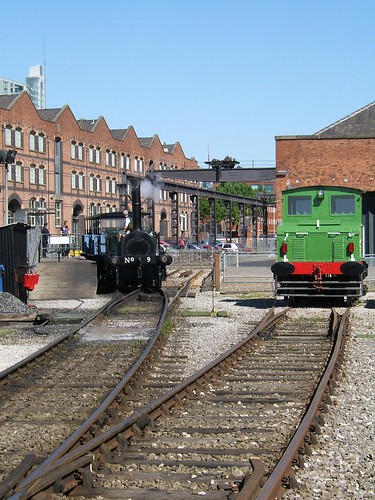
At Manchester, the Museum's 'main line' originally divided into three sidings in the Upper Yard. The siding nearest the Power Hall had the inspection pit and was used for engine preparation. The next line was fenced to form the running line. The third siding was in the public area and rarely used, although (soon after I became involved) I remember a preserved tram converted for battery operation giving rides along this siding on special occasions. There was an island platform in between the inspection pit siding and the running line, equipped with a rather nice umbrella roof. Clearances didn't allow both lines to be used for passenger trains so the end of the inspection pit siding stabled a converted coach as a cafe run by volunteers with the name 'Chuffers'. The picture below of 'Planet' also shows the converted coach and the platform roof - both features now gone.
 'Planet' (and a younger Jan) at the original platform at Manchester some time in the early 1990s (Photo: L. Walker, Wigan).
'Planet' settled into her role giving public rides in the Museum. Her appearance certainly caught the imagination of the visitors, although they were sometimes reluctant to believe that she was newly-built and not the original locomotive restored. For drivers, the slip eccentric valve gear could prove frustrating when it came to changing direction. A modern innovation was a valve gear indicator on the footplate to assist drivers. However, being chain driven, the indications could not be relied on and were best ignored (I was reminded of the comment about the indicator for the steam reverser on some Bulleid engines - "The biggest liar on the footplate"). Over the years, a number of alterations have been introduced to improve reliability.
Usually, 'Planet' runs with the two reproduction semi-open coaches but, occasionally, there's a little variety. When the replica was first commissioned, the handsome M.S. & L. 'tricomposite' coach was available. Later, the restored London and Birmingham Railway coach was used on very special occasions, as shown on the picture below.
 'Planet' with a train including the restored London & Birmingham coach (Original Photo: MOSI).
The railway facilities were changed when the Museum decided that further parking facilities were needed in the Upper Yard. The third siding and platform were lost and the running line was shortened so as to terminate on the Water Street side of the power Hall. A new platform was constructed on the 'stub' of the third siding. The picture below shows the revised arrangements which had the effect of making the railway operation rather remote from the core of the Museum.

'Planet' at the now-abandoned platform on the shortened running line.
The trackwork was altered in the vicinity to the 1830 Warehouse, to provide a loop on the running line and an additional siding. These facilities were intended to allow greater operational flexibility, particularly on special occasions.
In 2005, 175 years after the opening of the Liverpool and Manchester Railway, the Museum of Science and Industry celebrated with the 'Riot of Steam' event, featuring replicas of contenders from the Rainhill Trials, together with the 'Planet' replica and, sadly not in steam, the veteran 'Lion'. The additional track facilities were fully utilised for this event. My pictures of 'Riot of Steam' are here.
 'Riot of Steam' showing (L to R) 'Lion', 'Sans Pareil', 'Planet', 'Rocket' and 'Novelty'.
In 2009, it was decided to re-instate the running line to its original length. The original running line and the third siding had been lost during the car park extensions but the siding nearest the Power Hall (with the all-important Inspection Pit) remained. A new single platform was built on the car park side of the remaining siding, as shown below.
 'Planet' standing at the platform now in use, with the Inspection Pit in the foreground.
In August 2009, 'Planet' welcomed a number of visiting locomotives during the 'Transport Festival'. There's a report hete
 During the Transport Festival, 'Planet' hauls the passenger train, passing the 1879-built Beyer Peacock works shunter.
In 2010, a somewhat less-ambitious gala, featuring the 'Planet' replica and National Railway Museum's 'Rocket' replica, commemorated 180 years of the Liverpool and Manchester Railway. See my set of photographs titled Liverpool & Manchester 180th.
 The 'Rocket' and 'Planet' replicas celebrate the Liverpool and Manchester Railway's 180th Birthday.
Out and about
Over the years, 'Planet' has made a number of visits to other sites, including Llangollen, Locomotion, Beamish, Great Central and National Railway Museum York. The only visit I was personally involved with was to York, which was great fun.
Still going strong
Any steam locomotive requires quite a lot of maintenance but, given that attention, a locomotive can have a long life. We look forward to 'Planet' continuing to thrill people with the "magic of steam" for a long time to come.
 'Planet' on the 'Pineapple Line'.
Related posts in this blog
Early Locomotive Design.
The Planet Replica.
My Pictures
'Planet'.
Museum of Science and Industry, Manchester.
Liverpool & Manchester 175th.
Liverpool & Manchester 180th.
2009 Transport Festival.