Events of Wednesday, 4th April
I performed the daily exam and check of levels then attempted ground start of the four 150 horse power 'flat six' bus engines. This is carried out on each underframe-mounted engine control panel in turn, holding the manual throttle in 'full rack' position whilst pressing the electric start button until the engine is firing.
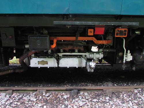
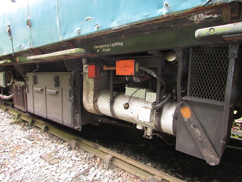
'Flat Six' 150 h.p. bus engine. The red-painted box is the battery charging point. The orange-painted box top right is the engine control panel.
The manual throttle is then progressively eased back to the 'idling' position. To avoid the engine cutting-out, this may take a few seconds. If the engine does stop, a fresh attempt at 'cranking' can only be made after a short delay. The two engines on the single unit 'Bubble Car' started fine but neither engine on the other vehicle would crank. In each case, the starter solenoid came in with a reassuring 'clunk' but there seemed very little movement of the engine. Since both engines were similarly affected, I diagnosed discharged battery. Each vehicle has its own heavy-duty lead-acid 24 volt battery but the heavy current demand when starting each engine means that a good battery in an adjacent vehicle cannot be used to 'jump start' a failed car. The service could have been performed with both cars if one of the two failed engines could have been started, in which case the final drive on the failed engine would have been isolated but this is not recommended with both engines on a power car 'out'.
The vertical bar is the Final Drive Isolating Switch in the 'engaged' position. When horizontal, the drive is 'isolated'.
There seemed two options: put the discharged battery on mains charge or 'ditch' the problem car, performing the service with just the one-coach 'Bubble Car'. Depending on the charge remaining in the battery, it was possible that an hour's charging would allow engine start but, adding the time to connect up and remove the mains charger, that would have put the start of service seriously late. So, after a brief discussion, it was agreed to use only the single unit, which was the vehicle at the southern end of the set. So the 'Bubble Car' had to propel the failed vehicle out of the way at the north end of the station, 'tie it down' and then split the two vehicles. I'd hoped that we might be able to recharge the battery during the day from one of the power sockets provided on the platform face but this did not prove possible.
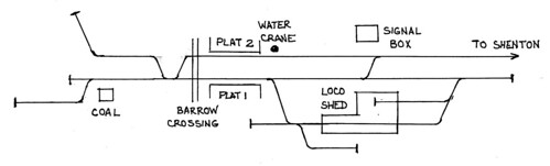
Shackerstone track diagram sketch. North is to the left on this sketch.
In the post Santa Specials at the Battlefield Line 2017 I commented "The rather cramped track layout at Shackerstone requires careful choreography to manage two trains" but, on the morning of 4th April, with various items of freight and passenger rolling stock awaiting shunting operations to be completed, our options were very limited and we decided to leave the failed vehicle in the north end of platform 1.
Splitting DMU vehicles, interconnected by a screw shackle, air hoses, duplicated vacuum hoses and various electrical jumpers is not a trivial task and I was grateful to Adrian for relieving me of this job.
 Click for larger image
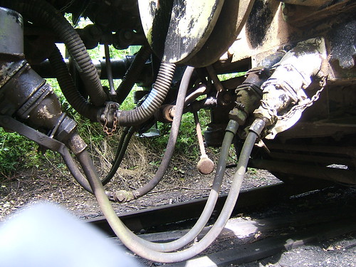
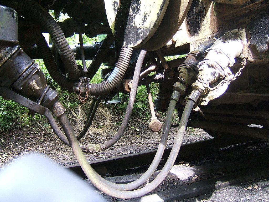
Details of the interconnections between vehicles.
The picture above shows the arrangement and, of course, there's not much room to work. Referring to the picture above, starting nearest the camera, you have:-
1. Jumper cable on left vehicle ('black') attached to multipole connector on right vehicle.Jumper cables not in use are 'stowed' in a receptacle adjacent to the jumper cable. 'Palm' couplings are standard on railways for air lines and they are mated and de-mated with an action similar to rubbing your hands together, hence the name. To avoid confusion between the two vacuum brake hoses, the fittings on the 'quick release' hoses are the mirror image of the standard coupling. On DMU, palm coupling fittings are often painted white, vacuum hose fittings red and 'quick release' hose fittings blue.
2. Jumper cable on left vehicle ('white')attached to multipole connector on right vehicle.
3. Control air hoses, joined with 'palm' coupling.
4. Vacuum brake train pipe corrugated hoses, joined with standard vacuum connection ('red').
5. Vacuum brake 'quick release' corrugated hoses, joined with 'reversed' vacuum connection ('blue').
6. Standard screw coupling on left vehicle, attached to right vehicle and tightened.
7. Standard screw coupling on right vehicle, not used and suspended from hook on underframe.
8. Jumper cable on right vehicle ('white') attached to multipole connector on left vehicle.
9. Jumper cable on right vehicle ('black') attached to multipole connector on left vehicle.
10. The round buffer heads nearer the camera are visible at the top of the picture.
Finally, the Guard placed an unlit oil tail lamp on the lamp bracket at the south end of the failed vehicle as a warning to the driver of an approaching train during the day (me!). By the time all this was accomplished, we were around ten minutes late and our passengers had already boarded the 'Bubble Car' so the Guard gave the 'Right Away' (two buzzes on the Guard/Driver annunciator) which I acknowledged.
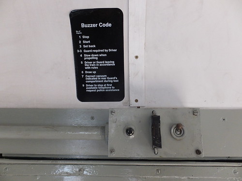
DMU: Guard's buzzer pushbutton and Buzzer Code.
We started our booked 'diagram' of four round trips to Shenton as the sky darkened and the weather deteriorated to heavy rain. I started the electrically-controlled diesel-fuel powered warm air heater and, after a while, the passenger compartment was quite cosy. The driver's cabs weren't bad, either.
Left: Battery Box, Right: Underfloor warm air heater.
Ritchie had installed new windscreen wiper blades as well but my initial optimism was tempered by the rather erratic wiper motion produced by the air motors. However, we completed our workings without incident and, by the time we'd finished, it had even stopped raining. It remained to retrieve the failed vehicle from the north end of Platform 1, stable on the DMU siding and put the battery on charge overnight ready for the next day. I closed up to the failed vehicle and Dave attached the screw shackle. I decided to leave all the jumpers and hoses disconnected, in case only the single unit was used the following day (we were not expecting large numbers of passengers).
However, when I'd shunted the failed vehicle that morning, I'd had the benefit of a working vacuum brake because it was still 'piped' to the Bubble Car so, once the vacuum was 'destroyed' the vacuum cylinders on each bogie applied the brakes. Although vacuum brakes will eventually 'leak off', in a well-maintained cylinder the brakes can remain applied for days before enough air leaks past the piston seal in the cylinder to reduce the partial vacuum above the piston and allow the brake blocks to release. Reliance is never placed on how good the leakage performance of a brake cylinder might be and handbrakes are always applied to an isolated vehicle. I had the choice of either re-connecting the brake hoses to the vehicle so that vacuum could be re-created below the piston or ensuring brake release by deliberately admitting air above the brake piston to destroy the persistent vacuum. This is done by opening a release valve associated with each brake cylinder. Because of the inaccessibility of these valves, there is normally a stout cord leading from the valve to framing on each side of the vehicle. Tugging on the cord opens the valve and, after a few seconds, the brake piston should have descended fully, releasing the brake.
In an ordinary bogie coach, the brake cylinders are normally mounted on the coach underframe, adjacent to each bogie. But in a DMU the underframe space is already filled with equipment - engines, transmission, compressors, exhauster - so the vacuum brake cylinders are mounted on the bogie frame itself, with the release cord on the outer end of the bogie. Manually releasing vacuum brakes on any type of vehicle is always called "pulling the strings".
With the brakes released, the Bubble Car then dragged the failed driving motor coach into the siding, allowing the 'big shunt' to be completed by a diesel shunter at some stage. The engines were shut-down, handbrakes applied to both vehicles and the battery charger was connected to the battery charging socket on the failed vehicle in the hope of restoring the battery overnight.
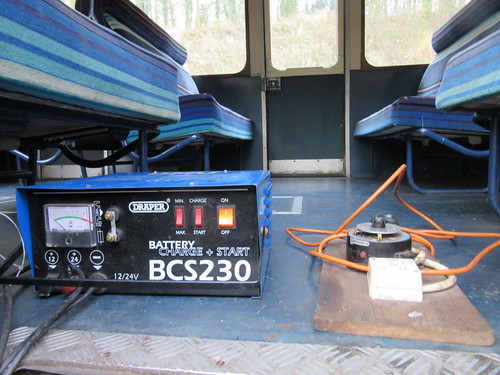
DMU at Shackerstone: Battery Charger.
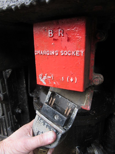
DMU at Shackerstone: Battery charging socket.
It just remained to complete all the paperwork and the day was done.
