skip to main |
skip to sidebar
The Mutual Improvement Classes (MIC) of the old steam railways continue for today's preservation volunteers. This article, taken from notes of talks given by Jan in 2002, is one of a series about working on preserved railways. You can display them all by clicking here or see an index of article titles here.
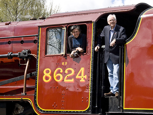
Pete Waterman and Jan on the footplate of 8624 at Peak Rail in 2010 (Photo: Sheila Rayson).
The Passed Fireman is normally rostered as a fireman but, having become a Passed Fireman, he is available to act as Driver when required. The candidate for passed fireman will be expected to have had significant experience (the required experience depends upon the railway) of working around engines, moving through the grades of cleaner, passed cleaner and fireman. The safety procedures necessary on locomotives should have become second nature and the candidate should be relaxed and at ease on the footplate, whilst remaining alert and aware of everything going on. Monitoring the state of the boiler, correct use of the injectors/dampers/blower should all come readily, together with an easy familiarity with firing. This allows the candidate, once passed for driving, to adequately supervise his fireman and, where necessary, give assistance.
A driver has to be in control - of him or herself, the fireman, the locomotive and the train. A good driver radiates quiet confidence which comes from mastery of driving and firing and a thorough understanding of the design and operation of all aspects of the locomotive.
This is quite a task which is why, before the Second World War, a railwayman could spend twenty years or more on the footplate becoming thoroughly conversant with everything he might need to know. In present day preservation, promotion to driver is likely to come much earlier. A professional railwayman will have spent every working day working on locomotives - a volunteer, however keen, is unlikely to have spent more than one or two days a week, if that. Accordingly, you need to compensate for the relative lack of experience partly by seeking a thorough understanding of the engineering theory underlying locomotive design and partly by consciously avoiding the complacency which familiarity may encourage. Safety comes through recognition of your own relative inexperience.
Locomotive Preparation and daily examination
On taking charge of a locomotive, you must ensure that the locomotive is in a safe condition - mid gear, cylinder drain cocks open, handbrake hard on, regulator closed and that the gauge frames are in the working position with sufficient water showing in the glass. You must make yourself responsible for the safety of the booked fireman and any rostered preparation crew working on the engine. Ensure that they report to you on arrival and do not leave for other tasks without your permission. You must set a good example for them to copy and not allow yourself to slip into sloppy or dangerous practices.
Boiler management during preparation is crucial and the driver must be able to supervise his fireman adequately, giving help and advice so that the fireman becomes more confident and more skilled. Effective preparation of the smokebox (char removed and door airtight), ashpan (ash removed and dampers working properly) and fire (clinker removed and firebars in good order) is vital to ensure complete combustion of every shovelful.
Although drivers will frequently allow their fireman or preparation staff to oil round the locomotive to gain experience, the daily examination is something a driver will want to perform himself. Be methodical, work round the engine checking for anything which may later become a problem. Examples are fractures, cracks, unexpected or unusual wear, damaged, bent or misplaced components, missing locknuts, cotters or split pins and, particularly, displaced spring hangers or broken springs. Check for any leaks (steam, water or oil). As far as oiling is concerned, ensure that any missing corks are replaced and check the condition of a sample of the trimmings. If possible, carry a small selection of corks so that any found missing or damaged can be replaced without the need to make a special journey. If a mechanical lubricator is fitted, ensure that this is filled with the correct grade of oil has been used and, when a priming handwheel is fitted, ensure that this has been operated so as to fill the oil delivery lines. Where a sight feed or hydrostatic lubricator is fitted, this must be carefully filled with clean oil, ensuring that it really is full.
Traction and Adhesion
We walk by trying to slide a foot backwards along the ground. Normally, there is sufficient friction between sole of the shoe and the ground to prevent sliding. Instead, the foot stays where it is but the body is levered forwards. However, if we try the same thing on ice, the friction between shoe and ice is much lower and the usual result is that the foot slides backwards. We can walk on ice only by deliberately reducing the sliding force generated by the muscles so that it is too small to break down the reduced level of friction between shoe and ice.
Moving a locomotive is a bit like walking on ice. A locomotive moves by applying torque (a turning force) to the driven axles. At the wheel tyre, this force attempts to slide the wheel on the rail. Under suitable conditions, sliding does not occur but instead the torque levers the engine forward so that a new part of the wheel tyre is in contact with the rail and the process continues. The force applied at the rail/wheel interface is proportional to the total area of the pistons on which the steam operates, the pressure of steam employed and inversely proportional to the diameter of the driven wheels. This force is usually termed the Tractive Effort of the locomotive, commonly expressed in 'pounds of force'.
Examined microscopically, neither the railhead nor the wheel tyre are smooth. For successful motion, there must be sufficient friction on the small area of contact between the tyres of the driven wheels and the rail for the engine to lever itself forward. The total friction is proportional to the number of driven wheels and the weight bearing down on each wheel - up to 10 tons or more on a large engine. If the torque applied to the wheels is progressively increased, it eventually exceeds the friction between wheels and rail and, at this point, wheelslip occurs. It is important that the driver reacts promptly to wheelslip to prevent damage to the engine by temporarily closing (or partly closing) the regulator. Remember that the response to closing the regulator will not be instant. The steam already in the main steam pipe, superheater elements (if fitted) and the steam chests will continue to drive the wheels for a time. Where a locomotive is fitted with a steam brake, some drivers will rub the brake to inhibit the slip and then reduce the braking effort as the slip dies away.
A cautious driver will avoid slips on starting by gradually opening the regulator until there is sufficient power to start the train moving. Once the train is rolling, power can be further increased to accelerate the train away. Variations in boiler pressure will clearly affect the power available - a larger regulator opening will be needed if the boiler pressure is lower than normal.
Clearly, the heavier the train or the steeper the gradient, the more power must be applied before the train moves away and the driver has to juggle the power to provide sufficient force to move without slipping. When the load is at the limit of adhesion, brief intermittent slipping may be inevitable.
The actual friction will vary according to the condition of the wheel tyres and the condition of the railhead. Rain has a profound effect and a slight drizzle will drastically reduce the friction between rail and wheel. During heavy rain, friction will tend to improve as the rain scours away the oil and grease which is normally present. Curvature of the track is also a factor. On a curve, the flanges of the driven wheels pressing against the outer rail may locally increase the friction available, but the rolling resistance of the train on the curve will also increase, requiring more power in any case. When moving through pointwork, values of rail/wheel friction on the driven wheels will fluctuate as the wheels pass through switch rails, check rails and crossings.
Engine weight diagrams show the theoretical static loads carried on each axle. The weight carried by the driving wheels determines the friction between tyre and rail and thus the amount of power which can be absorbed before wheelslip occurs. But, in traffic, the actual weight on each axle can vary quite widely, particularly if an engine has been roughly handled or spring characteristics are not ideal. Some locomotive designs include compensating beams to share the load between a number of axles but many types have independent suspension on each wheel.
Another factor to consider is weight transfer. Different designs and wheel arrangements have varying characteristics but many locomotives tend to rise up at the front when starting away with a load on the rear drawbar. This alters the distribution of load between the various axles. In a 'Pacific' the effect is unhelpful as it tends to 'unload' the coupled wheels and increase the weight on the carrying wheels at the rear, reducing the weight available for adhesion and thus the amount of power which can be applied without slipping. Any irregularities or undulations in the track such as a 'dropped' rail joint or pointwork in need of packing will also encourage this weight transfer effect, increasing the likelihood of slipping.
Although slipping is usually associated with starting a train away, high speed slips can occur, for instance when a locomotive running near the limit of adhesion hits a bad rail joint; a driver must be constantly prepared to take corrective action.
Braking
There's an old railway maxim 'Any fool can start a train, but it takes a driver to stop one'. As a fireman, you will have studied braking systems, but, in preparation for driving, you should review your understanding. When you're on a greasy rail with a few hundred tons on the drawhook is no time to realise that you've insufficient brake power! You must ensure that you are fully conversant with the various types of brakes, the method of testing them and the problems that you may encounter day-to-day. Remember, as a driver, there usually no-one to turn to for advice and you will have to decide how to tackle any situation.
Timekeeping and Economy
Drivers can be divided into three types, according to their response to a train which is delayed in starting. One type takes the view 'oh well, we're late already, a few minutes more won't hurt' and allows the delay to increase. The second type carefully maintains the scheduled sectional times but arrives as many minutes late as departure was delayed. The third type goes all out to recover the lost time. The third type of driver produces the most stirring runs and is the most widely reported but the second type of driver is usually the most economical. There is normally a price to pay in working locomotives to the limit: efficiency often deteriorates badly and water and coal consumption can be badly hit. Maintenance costs can also rise drastically due to increased wear. The expert driver will balance all these factors and will rarely, if ever 'thrash' an engine. A good driver will take pride in working to the schedule he is given in an economical manner and without working the engine harder than necessary. Drivers must thus be familiar with the factors which affect economy and must be able to choose the best method of working with any engine in any situation.
Boiler management crucially affects economy and the driver must supervise his fireman, giving help and advice where needed. Dampers and secondary air must be carefully regulated and the rate of firing adjusted to the needs of the job. The locomotive should never be allowed to blow-off as this represents a loss of coal and water. Boilers are usually most efficient when operated near their working pressure and the chosen pressure should be maintained as constant as possible for best economy. Good results on the road are often obtained by running the boiler at a constant rate of steaming. As the gear is linked-up, speed rises and when the cut-off is lengthened for hill climbing (using more steam per stroke) speed is allowed to fall, keeping demand for steam more-or-less constant.
Economy is best achieved by using steam expansively in the cylinders. When starting away, a locomotive might operate at a cut-off of, say, 75%. This means that the piston will complete 75% of its stroke before the steam supply is shut off by the steam valve valve. The volume of steam in the cylinder is then expanded by 1/3 as the piston completes its stroke before being exhausted through the blast pipe to the chimney. Once under way, the cut-off might be brought back to, say, 50%. This means that the steam valve will now cut off the steam supply when the piston has completed only half its stroke. The half cylinder-full of steam will expand itself to fill the cylinder - expansion to twice the original volume - before the steam valve opens to exhaust the used steam. As steam is expanded in the cylinder, it continues to do work in pushing against the piston and the steam is cooled. The exhaust steam is thus cooler when an engine is 'linked up' to an earlier cut-off than in full gear and this means that more work is extracted from the steam. In addition, when linked-up, less live steam is drawn from the boiler on each stroke, allowing the locomotive speed to increase without demanding a higher rate of steaming from the boiler. What must be avoided is expanding steam so much that the temperature falls sufficiently for the steam to condense into water. This not only chills the cylinder Casting (wasting syteam on the next stroke in warming the cylinder again) but leaves water in the cylinder which may not be swept from the cylinder during exhaust as more fluid steam would be. The advantage of using superheated steam is that its initial temperature is higher than saturated steam at the same pressure and so a greater expansion ratio may be used without risk of condensation in the cylinder.
When an engine is in full gear, the travel of the steam valve is at its maximum and so the maximum possible openings are obtained during admission and exhaust. As the gear is linked-up, the travel of the steam valve is shortened so that steam is cut off earlier in the piston stroke. But this means that the maximum possible opening no longer achieved and making complete exhaust of the used steam more difficult. This tends to require more live steam to counteract the back pressure produced by the exhaust steam as it is forced out through the restricted exhaust port, impairing the economy of the engine. Valve travels on slide-valved engines were in the order of 4 - 5 inches. Because of the design of the unbalanced steam valve, shorter valve travel meant less work was wasted in moving the valve against friction. Balanced slide valves allowed larger designs to be produced but these gave way to balanced piston valves where much less work was wasted, allowing the advantages of long-lap, long-travel valves to be exploited.
This is a list of the (very occasional) posts about Work. I started working for a Wolverhampton company, Contactor Switchgear (Electronics) Limited around 1961 but, with the encouragement of my mother, set up on my own as an electronics engineer in 1966. Ford Electronics Limited was incorporated in 1977. The last 50-odd years have been a roller-coaster ride which I wouldn't have missed for anything.
Posts are listed in reverse date-of-posting order but, just to confuse, each post describes events any time from the previous day to fifty years earlier. Alternately, selecting 'Work' in the list of 'Labels to select a blog topic' will find all the posts about Work (again, in reverse date-of-posting order). Finally, the Search Box in the page header (with the magnifying glass symbol) will find posts including any particular word or phrase.
Trade Show at the National Exhibition Centre 19-Sep-2021
Railway Engineering Works, Acton 5-Apr-2021
Telecommunications and Jan 10-Nov-2020
Railway Trollies 16-Oct-2020
UKRRIN Annual Conference, 21st November 2019 27-Nov-2019
Work (part 2) 7-Feb-2018.
Northern City Line 30-Jan-2018.
Rail Industry Information Day, 2018 17-Jan-2018.
Quinton Rail Technology Centre 2-Jan-2018.
Rail Research UK Association Annual Conference 2017 20-Nov-2017.
Class 373 Test Train to Paris 3-Apr-2017.
Class 373 Test Train to Grantham 8-Mar-2017.
Electrification Telephone Systems for British Rail 9-Nov-2015.
Starting my own business 4-Nov-2015.
Visiting Steelworks 22-Oct-2015.
London Underground and Jan 6-Oct-2015.
The World of Work 3-Apr-2014.
My First Trip to India (continued) 12-Jan-2013.
Crewe International Electric Maintenance Depot 17-Jan-2008.
Brewood Hall Small Barn 10-Jan-2008.
My first visit to Taiwan 3-Jan-2008.
Testing Class 395 Trainsets 18-Dec-2007.
Visit to Seoul, South Korea 14-Jun-2007.
Oil & Gas Industry 13-Jun-2007.
Working in Holland 19-Jan-2007.
Working for the Big Boys 17-Jan-2007.
If it were easy, everyone would do it 16-Jan-2007.
My first trip to India 5-Jan-2007.
Train Dispatcher Project - Thailand 5-Jan-2007.
Work 3-Jan-2007.
Some of the above posts have links to albums of photographs which can be viewed or downloaded in various sizes. Alternately, you can go to a list of my photograph albums about Work here and look for a particular picture.
[Updated 19-Dec-2019: Updated 22-Jan-2023]
This is a list of posts about railways in Myanmar (Burma), covering the nationalised railway, Myanma Railways, Yangon trams and a couple of long-gone light railways. My first visit to Myanmar was in 2008 and I've returned (in connection with charitable work) at least once a year since. Most are fairly technical railway articles but I've included more general travel posts which have some technical railway content which may not appear elsewhere. Since the early posts, I've learnt more so you may find contradictions. Hopefully, the later posts are more accurate (but I offer no guarantees). There are lots more posts describing my various visits but, unless a post has technical railway content, they are not in this Index. I hope that isn't too confusing. Posts are listed in reverse date of posting order.
Railway Carriage Building and Repair in Myanmar 8-Aug-2021
A trip to Bago - Technical Notes 6-Dec-20
Power Signal Box, Togyaunggalay 24-Jun-2020
Railway Operation Control Center, Yangon 05-Feb-2020
Visit to 'Mandalay Tower' 29-Jul-2019
Return to Burma 5-May-2019 (Yangon Central and Togyaungkalay)
Bago - Yangon by train 10-Mar-2019
Kalaw - Shwe Nyaung by train 20-Jan-2019
A trip to Bago 10-May-2018
Gokteik Viaduct Notes 9-May-2018
Gokteik Viaduct 8-May-2018
Train movements at Yangon Central station (3) 1-Apr-2018
Train movements at Yangon Central station (2)31-Mar-2018
Final day in Yangon and the Circle Line 22-Nov-2017
Rail-mounted Cranes on Myanma Railways 13-Nov-2017
Non-operational steam in Myanmar 13-Nov-2017
Mandalay and its Circle Line 26-Oct-2017
Mandalay Wednesday 17-Oct-2017
Around Mandalay 15-Oct-2017
Features of Railway Signalling in Myanmar (pictures links)
Train movements at Yangon Central station
Last Full Day in Yangon
Myanmar, Railways and Jan
A Short History of Yangon's Electric Railway
Insein Railway Station
Thazi - Kalaw (part 2)
Thazi-Kalaw
Da Nyn Gone Railway Station, Myanmar
Around the Circle Line in 2016
Kyee Myin Daing Railway Station
Railways in Burma
Last Day in Yangon
Thazi Railway Station and Diesel Locomotive Depot
Trams Return to Rangoon
The Arakan Light Railway
Ywa Taung Locomotive Workshop
Rangoon Tramways
New Railway from Katha to Bhamo
Permanent Way in Myanmar
The Madaya Light Railway
Thaton – Duyinzaik Railway
Insein Locomotive Works
Yangon (Part 2)
Yangon (Part 1)
Diesel Traction in Burma
Cab Ride around the Circle Line
Yangon Central Power Signal Box
Relaxing at the Strand Hotel
Exploring Yangon's railways
Railways in Myanmar
Freight Rolling Stock in Burma
Passenger Rolling Stock in Burma
Diesel Railcars in Burma
By Rail to Maymyo
Back to Yangon
Mandalay Area Railways
Napyidaw
On to Yangon
Yangon Area Railways
Bago to Kyaikto by Train
The Circle Line Revisited
By Train to Naba
Yangon to Kyaikto by Train
Cab Ride back to Katha
Cab Ride from Katha
The Circle Line, Yangon
Some of the above posts have links to albums of my photographs which can be viewed or downloaded in various sizes. Alternately, you can go straight to a list of my collections of pictures of railways in Myanmar here and look for a particular album.
There is also a series of posts in which I attempt to summarise my observations of railway signalling on Myanma Railways. This has a separate already-published index here, but the links are repeated below.
Railway Signalling in Burma - Part 1: Semaphore Signals.
Railway Signalling in Burma - Part 2: Colour Light Signals & Motor Points.
Railway Signalling in Burma - Part 3: Control of Trains.
Railway Signalling in Burma - Part 4: Manual Control of Points and Interlocking.
Railway Signalling in Burma - Part 5: Signal Boxes with Interlocking Frames.
Railway Signalling in Burma - Part 6: Signal Boxes with Electrical Interlocking.
Railway Signalling in Burma - Part 7: Telecommunications (in preparation).
[Updated 14-Sep-2018, 23-Jan-2019, 11-Mar-2019, 31-Jul-2019, 31-Mar-2020, 24-Jun-2020, 31-Dec-2020, 9-Aug-2021]
My trips to Liverpool are normally by train but much of the city's fame arises from its importance as a sea port, situated on the River Mersey. Arriving at Liverpool by sea involves various problems for mariners - the River Mersey has the second highest tidal range in Britain, with spring tides exceeding 10 metres and entrance to the river from the sea is impeded by Coastal Bars.
Coastal Bars
Coastal bars (often referred to simply as 'Bars') are shallows or shoals in the sea bed formed by the movement of sand and sediments where the tide meets the flow of a discharging river. Navigating through these areas is called "Crossing the Bar". Apart from the risk to ships of grounding on a bar, in some weather conditions seas breaking over the bar create additional hazards, requiring good local knowledge for safe passage.
Liverpool Shipping in 1870
Commenting on the approach to Liverpool from the sea, the 'West Coast Pilot' for 1870 states "The numerous sands which encumber the entrance of the Mersey will be better understood by a reference to the chart than by reading the most elaborate description." At that time, there were various land-based lighthouses, three light vessels (North West, Formby and Crosby) and an elaborate system of buoys to identify the channels. Because of these hazards, it was compulsory for all ships to take a pilot with up-to-date local knowledge. There were 12 pilots who cruised in pilot sailing boats, ready to board ships and take charge of the navigation. The pilots were controlled by Mersey Docks and Harbour Board.
Continued dock expansion
The success of the port of Liverpool meant that expansion of the docks continued until the 1920s (see Notes on Liverpool and its Docks). During this period, steam propulsion replaced sail, iron and steel replaced wooden construction and vessel sizes increased, so that most shipping became concentrated in the dredged channel now known as Queen's Channel with the 'Bar' lightship serving as the pilot rendezvous location for inbound ships.
Liverpool 'Bar' Lightship
In 1947, the 'Bar' lightship duty was being carried out by the 'Alarm', shown in the aerial view below.

Mersey Bar Lightship 'Alarm' and SS 'Collegian', Liverpool Bay, 1947.
The firm of Philip and Son built the relacement lightship 'Planet' in 1969 which, with its crew of seven, became the Mersey 'Bar' lightship. There's a Wikipedia article on the lightship builder here. In 1972 an unmanned buoy replaced the lightship which was sold to Trinity House and continued to serve at various sites before being retired in 1989. Saved for preservation from the breakers, she eventually saw service as a cafe/bar and museum whilst moored in Canning Dock, Liverpool, where I took the photograph below.
 The preserved Lightship 'Planet' in Canning Dock, Liverpool.
Following a long-running dispute between the owner of 'Planet' and the Canal and River Trust, the lightship was seized by bailiffs in 2016 and towed to Sharpness where it faces an uncertain future. There's more information about 'Planet' on the interesting Offshore Radio Museum Site.
The unmanned buoy which replaced 'Planet' in 1972 was known as a Large Automatic Navigation BuoY (LANBY buoy). The design, featuring a circular hull and central mast provided with a powerful light, originated in America and was adapted for use in Britain. According to research by the Mersey Lightvessel Preservation Society, the LANBY buoy was, in turn, replaced in 1993 by what I believe is still the current installation known as Light Float 'Bar Racon' and operated by Trinity House.
'Bar Racon'
The addition of 'Racon' to the name indicates that, in addition to the normal light signal, the installation provides an identifiable radar return (the name is a contraction of RAdar beaCON). The widespread introduction of Radar on ships represented a significant advance in safety and the addition of a radar transponder to a buoy means that, when the transponder receives a radar pulse from a ship, it transmits a return signal including a simple identity, which assists the correct identification of the radar return received by the ship.
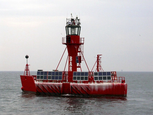 Light float 'Bar Racon' in Liverpool Bay (Photo: Fuelcellworks).
An article in Fuelcellworks here discusses the installation of a methanol fuel cell to improve the endurance of the light float.
'Crossing the Bar'
The term is familiar to many people as the title of a short poem by Alfred, Lord Tennyson (1809-1892), a celebrated poet from the Victorian era whose works remain popular. He uses leaving harbour and sailing out to sea as a metaphor for dying.
Sunset and evening star
And one clear call for me!
And may there be no moaning of the bar,
When I put out to sea,
But such a tide as moving seems asleep,
Too full for sound and foam,
When that which drew from out the boundless deep
Turns again home.
Twilight and evening bell,
And after that the dark!
And may there be no sadness of farewell,
When I embark;
For though from out our bourne of Time and Place
The flood may bear me far,
I hope to see my Pilot face to face
When I have crossed the bar.

Alfred, Lord Tennyson with his wife Emily and sons Hallam and Lionel.
Wikipedia has an article on 'Crossing the Bar' here, suggesting that the verses were inspired by a crossing of the Solent to his home at Farringford House on the Isle of Wight. There's more about Farringford House and the famous people who settled in the area at the website Tennyson’s Celebrity Circle.
Liverpool Shipping today
Shipping in the Mersey today is very different from that in 1870 but sands remain a problem and continuous dredging operations are necessary to allow large, modern ships access and charts are still essential (although, increasingly, those charts are electronic). Although the structures of the former light houses survive, none are now active light houses but the "elaborate system of buoys" already established in 1870 has been modernised and complies with one (of two) internationally-recognised systems of navigation buoys. But, despite all the improvements brought about by the use of radio, radar, AIS and Electronic Chart Display and Information Systems (ECDIS) which I discussed in the post Watching The Ships Go By, the system of using a human pilot with hard-earned experience of the local conditions remains a vital part of bringing ships safely in and out of the Mersey.
My first, short post on the subject of 'Work', back in 2007, is here. It's a theme I've returned to erratically since and you can find all these posts here (or click on 'Work' in the 'Labels to select a blog topic' list). This post gives a little more information on some of the projects I've worked on, mainly covering railway projects up to around 2000. In the future, I hope to write a little about early industrial projects and more recent activities.
The post The World of Work described my introduction to industrial electronics when I worked at Contactor Switchgear (Electronics) Limited in Wolverhampton.

This cast nameplate (in various sizes) was attached to panels made by Contactor Switchgear Limited (Photo: Wolverhampton History and Heritage Website).
In 1966, I decided to set-up on my own, and the post Starting my own business describes the initial slow progress, producing industrial control equipment for a few clients before my former employers asked if I could design and build a Ships Movement Indicator for Dover Harbour Board. With help from friends who had also moved on from Contactor Switchgear(Electronics) Limited, we produced the remarkable affair and commissioned it in the windswept Dover Harbour Port Control building on the Eastern Arm breakwater projecting into the English Channel. The specifiers of the equipment had not troubled to ask the users what they needed resulting in the equipment being unloved by the people it was intended to help and it was removed after a few years service. Later in my career, I learnt that the Ships Movement Indicator project was by no means unique in failing to determine the real needs of the intended users. I'd invested so much energy in doing the best job I could, when the redundant system was offered at scrap price, I bought the equipment back and it still moulders in storage.
The above post Starting my own business also describes the selective call equipment we produced for Gerry Gardner for use over private mobile radio. This work was more successful and I learnt a lot from our gruff, rather eccentric client. I also experienced my first flight, described My First Flight.
I managed a few more light aircraft trips in connection with the business. starting with a flight to a steelworks on Teesside, described here. This resulted in our producing Electronic Vibratory Feeder equipment for a number of steelworks on Teesside and elsewhere. There's an introductory article on my association with steelmaking here but I hope to recount more experiences in the future.
In those early days, we produced a few small railway telephone systems. Two were for the Kowloon-Canton Railway: one (for ML Engineering) which they installed at the Hung Hom terminus in Hong Kong and, later, one (for Westinghouse Brake and Signal) for Sha Tin. Westinghouse Brake and Signal also ordered small railway telephone systems for use at the modernised steelworks at Redcar and Ravenscraig.
In 1970, based on the success of our selective call equipment for Gerry Gardner, British Rail approached us about the possible supply of selective call telephone equipment for use over wire. This was in connection with the electrification between Crewe and Carlisle. The above post Starting my own business includes a brief account of this period. Up to around 1980, we periodically received further orders for this equipment, involving large numbers of waterproof trackside telephones and electronic equipment racks at the Power Signal Boxes at Warrington, Preston and Carlsle.
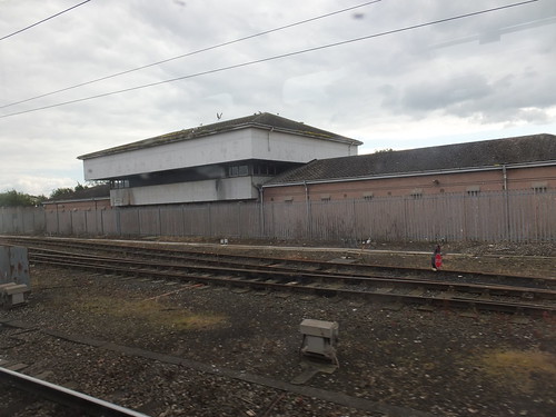
Carlisle Power Signal Box.
Westinghouse Brake and Signal gave us an order in 1972 for a new design of selective call telephone equipment for use on the Centralised Traffic Control (CTC) scheme between Dublin and Ballybrophy in the Republic of Ireland. Various staff from Ford Electronics, including the writer, made a number of trips to Eire during the installation and commissioning phases. It was an interesting time which I've not yet described and, at the moment, there are no pictures.
Around that time, we also produced electronic Signal Post Telephone (SPT) equipment which was installed in Northern Ireland, a few locations on British Rail and at one or two Power Stations.
The original selective call telephone systems for British Rail were fairly successful, leading to further development resulting in an enhanced version with multi-party conference capability for use as Electrification Telephones. This equipment is outlined in the post Electrification Telephone Systems for British Rail. Altogether, we supplied equipment for three installations of this type of system for London Midland, Scottish and Eastern Regions of British Rail. This, and sub-contract manufacture of other telecommunications equipment for British Rail kept us busy for a few years.
In 1976, we negotiated a large order from G.E.C. to supply a specially-designed selective call telephone system for use on the Trunk Line Electrification Project in Taiwan. I learned many valuable lessons working for G.E.C. which I talk about in the post Working for the Big Boys. The G.E.C. order included modular telephone concentrators and a large number of trackside Wayside Telephone boxes mounting a multi-circuit telephone and disconnection terminals for the lineside telephone cables. On this project, the consultants were German so, in the design stages during 1976, that gave me a couple of visits to Frankfurt. Commissioning and resolving problems which arose with the selective call system resulted in my making, I think, three visits to Taiwan during 1977 and 1978. There are no technical reports at present but my vivid impressions on my first visit to Taiwan are in the post My first visit to Taiwan. We received further orders for this equipment in 1981, 1988, 1990 and 1991.
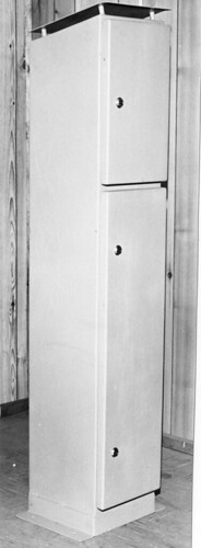
Housing for trackside Wayside Telephone: The upper compartment mounts a multi-circuit telephone, the lower compartment is used for cable termination, equipment mounting and power supplies.
Canadian Aid funded an interesting railway traffic control system for Malawi in 1977. We produced what we thought was a neat electronic version of the venerable Western Electric electromechanical impulse selective telephone equipment. Standard Telephones and Cables produced electromechanical equipment similar to the Western Electric equipment for a time and adapted the signalling principles in their electromechanical Signal Post Telephone equipment widely used on British Rail. Despite the elegance of our system, we didn't have much commercial success.
By this time, I seemed to have gained some sort of reputation and I was flattered when the mighty Philips invited me to do some consultancy work on railway telecommunications in 1980. This interesting period is touched on in the post Working in Holland.
Iraq were building a new railway linking Mosul, Kirkuk and Haditha (at that time, oil-rich Iraq was regarded as an attractive client although I had my doubts). Philips were bidding to the Korean firm Hyundai for the telecommunications package for the railway but they ultimately walked away, convinced they couldn't make a profit at the price Hyundai was prepared to pay. There's a report here. Despite some disappointment, the wisdom of their decision was not lost on me and when, some months later, G.E.C. offered me a large sub-contract for the same project although we were short of work I declined. As I watched G.E.C. lose significant sums of money on the scheme and their chosen sub-contractor fall into bankruptcy, I regarded my decision as one of the best I'd made.
We produced another large system of railway selective call telephone equipment for G.E.C. in 1985, when the Ferrovia do Aco in Brazil was electrified to bring iron ore from the mountains near Belo Horizonte down to the deep-water port at Sepetiba. It had been arranged that I would visit Brazil in connection with the commissioning but, to my disappointment, it didn't prove necessary and my first visit to Brazil was not until 2005 (forming part of the trip 'Round the World 2': e-mails sent to friends from that trip were subsequently converted to the blog post here). We received a further order for test equipment for use on the Brazil system in 1991.
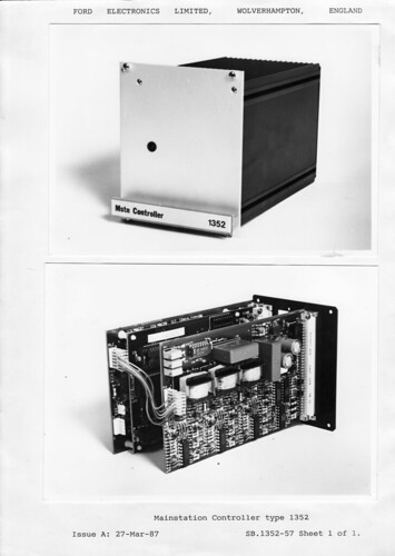
Mainstation Controller type 1352 is part of the system supplied to the Ferrovia do Aco. The rugged aluminium module housing is common to the whole range. The lower view shows the printed circuits assembled onto the back panel with the case removed.
In 1987, we did an interesting project with STC Telecommunications who, by then, were part of Northern Telecomm in which we licensed one of our selective telephone system designs, allowing STC Telecommunications to procure and build the equipment at their manufacturing site in South Wales. The equipment was to re-equip the Suburban railway network around Mumbai (which, back then, was still called Bombay). I didn't get to visit India during that commissioning, either, so my first trip to India was in 1992, in connection with commissioning equipment for the Delhi Ring (described later in this report).
G.E.C. bid on a project in 1987 to replace ageing electromechanical Train Despatcher Telephone Systems throughout Thailand. The equipment being replaced was impulse-selective equipment built by Standard Telephones and Cables in England of the pattern mentioned in the paragraph on Malawi above. The project was being funded by Japan so the consultants were Japanese and the specification had been very tightly-drafted in a way that made it very difficult to offer a compliant bid. There were many ups and downs on this project, not least because G.E.C. had seriously underestimated the costs of installation and commissioning in Thailand. For many months, we had an engineer based in Thailand, providing technical assistance to G.E.C. and training Thai Railways staff. I also made five visits in 1988 and 1989 during which I travelled widely around the country. At the completion of the project, G.E.C. held an 'I & C Seminar' in Bangkok which has a report here, with links to my pictures (scanned from 35mm prints).

Train Despatcher Equipment for Thailand under test in Wolverhampton.
When G.E.C. provided telecommunications systems for the Delhi Ring resignalling project, they decided to contract another company for the selective call telephones. However, serious problems were experienced with speech quality when the system was installed in 1992 and we were asked to urgently look at the problem. We didn't see a major difficulties with the basic selective call telephone system but the problems in transmitting over a complex loaded cable network had not been fully understood. We re-designed the audio transmission, using a network of 2-wire adaptive audio repeaters with programmable build-out for use on loaded lines and associated battery-backed power supplies. I was in India almost seven weeks installing and commissioning our modifications. There's a short post here with a link to a more detailed report.
In 1993 G.E.C. asked us to quote for Tunnel Telephone Equipment for the new Jubilee Line Extension Project. None of our existing designs of telephone system seemed adaptable - the major function of the Tunnel Telephone system is to provide a highly-dependable emergency shutdown system for the traction current. I recommended that they try Westinghouse (who had, I'd found out, previously supplied tunnel telephone equipment for the Central Line). A few months later, G.E.C. repeated the request and this time we agreed to quote. We supplied the equipment for the Jubilee Line Extension and we're still occasionally supplying tunnel telephone equipment for use on London Underground. There's more in the post London Underground and Jan.
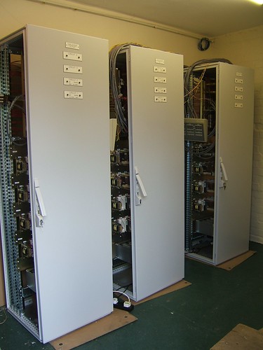
Tunnel Telephone Cubicles for Northern Line under test in Brewood.
More when I can.
Related posts on this website
For ease of reference, this list duplicates links in the above text.
Work.
The World of Work.
Starting my own business.
My First Flight.
here.
Visiting Steelworks.
Electrification Telephone Systems for British Rail.
Working for the Big Boys.
My first visit to Taiwan.
Working in Holland.
Visit to Seoul, South Korea.
Round The World Two.
Train Dispatcher Project - Thailand.
My first trip to India.
London Underground and Jan.
Liverpool, the River Mersey and Merseyside have interested me since my childhood visits. My first blog post was simply called Liverpool but there a quite a few now. You can find them all here (or click on 'Merseyside' in the 'Labels to select a blog topic' list). Although my home is some 80 miles from Liverpool, through the magic of the Internet I can "watch" shipping around Liverpool.
Wirralcam.org
'www.wirralcam.org' operate a number of webcams giving still pictures, generally updated twice a minute, from various locations on the Wirral. This offers an intriguing view of ships coming and going but, of course, doesn't provide information on the identity of the vessels or their itineraries.

Webcam view of the Mersey from Birkenhead Priory, with the twin towers of the Liver Building on the left and Albert Dock in the centre (Picture: wirralcam.org).
Automatic Identification System (AIS)
As an aid to maritime safety, most modern ships are fitted with Automatic Identification System (AIS) equipment, mandated by the International Maritime Organisation (IMO) under their Safety of Life at Sea (SOLAS) regulations. AIS installations on ships combine data regarding the ship's identity, destination, location as determined by GPS (Global Positioning System) equipment, together with heading and speed and transmit it periodically digitally by VHF (Very High Frequency) radio. The data is received and decoded by other ships in the vicinity and, where there is line-of-sight communication, also by various shore stations. Many ships also send and receive AIS data using Inmarsat communications satellites which (via satellite downlinks) makes the data available to ground stations lacking line-of-sight VHF communications with a ship. With digital communications and the internet, AIS data around the globe can be consolidated into vast databases of shipping movements. There's a Wikipedia article about AIS here. For a more detailed treatment, try the PDF of the recommendation covering AIS issued by the International Telecommunications Union (ITU) M.1371-1 here. I think the standard is now at M.1371-4 but the PDF linked should give an idea of the complexity of the requirements. Atlantic Source is a Spanish supplier of AIS and other communications equipment whose website may be of interest.
Maritime Mobile Service Identity (MMSI)
AIS equipment makes use of a vessel's unique Maritime Mobile Service Identity (MMSI) which is described in another Wikipedia article here. Note that whilst MMSI, heading, speed and position are automatically derived from ship sensors, some data like destination and status ('underway', 'at anchor') is manually entered by the bridge crew and is sometimes inaccurate, so don't be surprised if a ship supposedly at anchor is making 15 knots! Because the AIS data can be transmitted by VHF radio, drop-outs or temporarily erroneous data are also possible.
IMO identification number
Most merchant ships are allocated an IMO identification number, displayed on the vessel, intended to enhance "maritime safety, and pollution prevention and to facilitate the prevention of maritime fraud". There's a Wikipedia article here.
Commercially-accessible data
Commercial sites like 'Marinetraffic.com' and 'Vesselfinder.com' collect and analyse data transmitted by ships fitted with AIS and make certain information freely available (with other information hidden behind a 'paywall'). These sites have vessel details and photographs in addition to information about present position and previous voyages. You can search for a particular vessel by name, MMSI or IMO.
The ShipAIS site
To display AIS data for shipping around Liverpool at home, I like enthusiast-run site ShipAIS with its sub-title "Watching the boats go by" which offers excellent coverage of Liverpool and other areas. I tend to default to the Liverpool Docks page here (which will update every 2 minutes), switching to the geographically-adjacent Bar Racon or Mersey River pages as necessary. They have a useful Frequently Asked Questions page here (which has thoughtful comments about security concerns which have been raised about the wisdom of making shipping movement data widely available). The site can also display each vessel's MMSI number (which is unique), name (which may not be unique) and IMO identification number (where allocated). There may also be other data and a photograph of the vessel.
Remote Ship Watching
The ShipAIS page will show vessels in the area covered by the map and some of these may be visible on one or more Wirralcam.org cameras. Unrecognised ships or vessels of particular interest can be followed up using the free data on one of the commercial sites. I find the quickest is often to give Google the search string , for instance 'ship 235112573', which quickly finds various offerings for ACL's Ro-Ro/Container ship 'Atlantic Star' on sites like 'Marinetraffic.com' and 'Vesselfinder.com'. More technical information may be available on the shipping line site, for instance, ACL have more information on this '4th Generation CONRO vessel' here.
Improved ship safety
The ability to remotely watch ships I find impressive but, of course, the justification for all these systems is improved ship safety. The introduction of Radar and Radiotelephony were significant milestones but, on many modern ships, the integration of electronic charts, radar, GPS, AIS and information from various ship systems into what's called Electronic Chart Display and Information Systems (ECDIS) furnishes a whole new level of safety-related information which can automatically generate alerts to potential hazards. There's an introductory article about ECDIS on Wikipedia here. As mentioned in some of my travel posts, I've managed to visit the bridge of a few vessels equipped with ECDIS and been fascinated. I'll write a little more when I can.
The Northern City Line is a short branch line in London with an interesting history.
History
The Great Northern and City Railway (GN&CR) was formed in 1892 to build an underground electric railway from Finsbury Park, on the Great Northern Line, to Moorgate Street in the City of London. Initially, the Great Northern Railway supported the scheme and, to allow through running of main-line stock, the double-track line was built mainly in twin 'tube' tunnels, each with a diameter of sixteen feet. However, problems financing the project combined with disagreements over joint operations meant that the line as built terminated in underground platforms at Finsbury Park underneath the Great Northern Railway station.
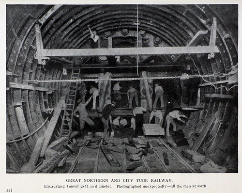
Great Northern and City Railway - driving 30 foot diameter tunnel section (Photo: Grace's Guide).
The line opened in February 1904 over a distance of three and a half miles from Finsbury Park to Moorgate in the city of London. Although powers had been obtained in 1902 to extend from the southern terminus around 500 yards to the Bank of England, this plan was abandoned after only part of the tunnel had been constructed. The isolated nature of the line prevented the railway from running at a profit but it was successful enough to be acquired by the Metropolitan Railway in 1913. In 1933, London Passenger Transport Board took control and the line became an isolated section of the Northern Line, called the 'Northern City Line'. It would have formed part of the proposed 'Northern Heights Extension' but this scheme was abandoned.
In 1964, Drayton Park became the northern terminus, allowing the original underground platforms at Finsbury Park to be used by the Victoria Line then being constructed. Highbury & Islington station was remodelled to allow interchange between the new Victoria Line and the Northern City Line. In 1970, the line was renamed 'Northern Line - Highbury Branch'. Around 1975, London Underground agreed to transfer the line to British Railways. However, before London Underground withdrew the service, Moorgate was the site of the worst London Underground train accident on 28-Feb-1975, killing 42 passengers and the driver. The excellent Railways Archive site has a summary of the report on this accident here, with a link to the full report which is well worth studying to understand the meticulous investigations carried out after major accidents.
British Railways Eastern Region converted the line from Drayton Park to Moorgate for their use, with 750 volt d.c. third-rail electrification and provided a connection from Drayton Park to the surface station at Finsbury Park, with 25 kV a.c. overhead electrification allowing the Moorgate Branch to form part of the Great Northern Suburban Electrification Scheme, finally realising the ambitions of the promoters of the Great Northern and City Railway in 1892! In 1976, services commenced to Welwyn garden City and Hertford north, extended to Royston in 1978. At that time, the Electrification Control Room (ECR) supervising the area was at Hornsey.
There's an interesting PDF by the London Underground Railway Society celebrating 110 years of the Northern City Line 110 YEARS OF THE GREAT NORTHERN & CITY published by here.
Rolling Stock
Electric Multiple Units were used from the opening in 1904, built by Brush (Loughborough) and The Electric Tramway & Carriage Works (Preston). By 1939, these units had been withdrawn and normal tube stock was in use.
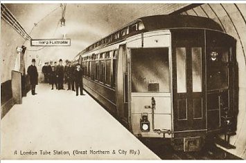
Original rolling stock on Great Northern and City Railway.
Since 1976, the line has been operated by dual-voltage class 313 EMUs running on the third rail system with tripcocks over the tunnel section and the overhead line equipment north of Drayton Park station. The EMU are arranged as 3-car sets with two driving motor cars and a trailer car. In peak periods, two 3-car sets work in multiple. Each motor car is equipped with four GEC G310AZ 82.125kW motors. For more information, see the Wikipedia article here.
This rolling stock is about to be replaced by a variant of the Class 700 'Desiro City' dual-voltage Electric Multiple Units, the Class 717 which is fitted with end doors for use on the Northern City Line, allowing passengers to be evacuated via the Moorgate Tunnel (as is possible with the 40-year old Class 313). At a recent Rail Industry Information Day (described here), I was surprised to find a full-sized Class 717 cab.
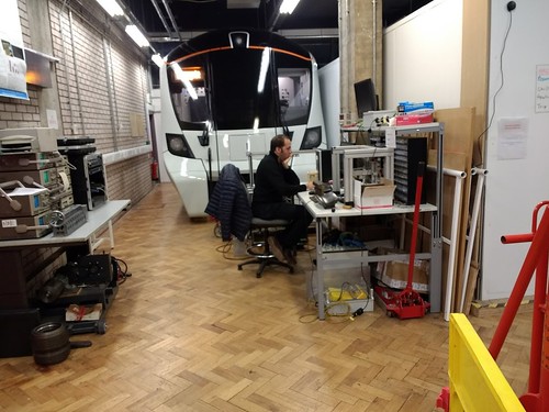
Rail Industry Information Day, 2018: Class 717 cab.
Electricity supply
Originally, power for the Northern City Line was produced at a dedicated generating station on the surface at Poole Street, roughly halfway along the route, directly above the twin tunnels. As mains electricity became available, the generating station was closed, being replaced by two traction sub-stations located at Finsbury Circus (adjacent to Moorgate station) and Queensland Road (adjacent to Drayton Park station). Around 1920, the abandoned generating station at Poole Street was converted into film studios for Gainsborough Films. At the time of my own first visit during a survey in 2006, the site was being re-developed as apartments.
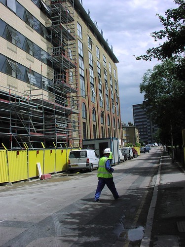
Former Gainsborough Studios, pictured during conversion into apartments (Photo: Thales).
Current was originally supplied at 575 volts d.c. using a fourth-rail system with each conductor rail placed outside the adjacent running rail (as on the Earl's Court experimental electrified train). By 1939, the conductor rail system had been converted to the standard London Underground fourth-rail system, as described in the posts London Underground - Traction Power Distribution and Fourth Rail Electrification. Transmission losses at 750 volts d.c. are relatively high and, to avoid excessive voltage drop, Traction Sub Stations (TSS) have to be located quite close together. When British Railways took over the Northern City Line, in addition to converting current collection to third rail, the power supply was upgraded. The conductor rail is divided into traction sections extending from one TSS to the next. Each section is double-end fed with d.c. from rectifiers at both Traction Sub Stations, to help to minimise voltage drop, particularly when more than one train is in a traction section.
Traction Sub-stations
The practical arrangement of a typical TSS with two rectifiers is illustrated in Figure 2.2 below. TSS for third rail conductor systems, are simpler than for the London Underground fourth-rail systems, since circuit breakers only need to switch the feed to the conductor rail.

The substation has two d.c. busbars linked or isolated by a coupling breaker. Each rectifier and each road supplied is associated with a circuit breaker. At most TSSs, the coupling breaker is normally closed so that both rectifiers and all four roads are connected together to minimise voltage drop. The TSS at Finsbury Circus and Queensland Road are simpler than the diagram, since each TSS only controls two traction sections.
Track Paralleling Huts
At some locations, Track Paralleling Huts (TPH) may be provided, rather than a full TSS. Each conductor rail is broken to form a section gap, but normally circuit breakerss are closed to connect together all conductor rails. Again, the aim is to reduce the voltage drop as a number of rectifiers can contribute current to each traction section. The arrangement is shown in Figure 2.3 below.

Jan's involvement
In 1974 my firm supplied an Electrification Telephone system for the 25 kV a.c. overhead electrified parts of the Great Northern Suburban Electrification Scheme, controlled from an Electrification Control Room (ECR) at Hornsey, as briefly mentioned in the post Electrification Telephone Systems for British Rail. This system extended as far south as Drayton Park but the tunnel section to Moorgate (being third rail d.c. electrified) was outside our scope and British Rail at York provided equipment for this section.
As described in the post London Underground and Jan, it was some twenty years later that my firm became involved in Tunnel Telephones for London Underground. As a result of our work with London Underground, in 2006 Thales contacted us regarding replacement of the life-expired tunnel telephone equipment on the Northern City Line.
The Northern City Line operates with a Traction Sub Station (TSS) at either end of the tunnel, with a midway Track Paralleling Hut (TPH) underground at Poole Street. Whilst the tunnel telephone system on the Northern City Line serves a similar emergency traction discharge function to London Underground systems, it also provides Signal Post Telephone functionality. Trying to understand the detailed functionality required was not helped by the fact that the late, unlamented Railtrack had managed to destroy most of the technical records of the earlier British Railways Eastern Region system, which used 3000-type Post Office relays. This equipment was located in an underground equipment room at Poole Street, accessed by a 50-foot descent from the surface via a steel ladder with safety landings set in a vertical shaft! We produced new equipment developed from our designs for London Underground and a re-configured layout moving the equipment to an existing telecommunications equipment room on the surface at Finsbury Park, providing easier maintenance access. The notes on the re-configured system below are derived from training material prepared by Ford Electronics Limited, with permission.
Notes on the re-configured system
The third-rail conductor system on the Northern City Line consists of a conductor rail laid along the track route allowing power to be picked up continuously by the train through its shoegear equipment. The conductor rail is laid outside the running rails and supported on porcelain insulators at a maximum pitch of around 4.3 metres. At turnouts, crossings and section gaps the conductor rails are broken. Ramps at the start of the conductor rail section lift the train collector shoes onto the rail and similar ramps at the end lower the shoes from the rail. The length of the gap depends upon the track feature. One of the two running rails is used as a traction current return, unlike the standard London Underground arrangement which also has a return conductor rail arranged for shoegear. However, Northern City Line does have a ‘fourth rail’ in the tunnel, spiked to the sleepers in between the running rails and frequently cross-bonded to the traction return running rail. This ‘fourth rail’ is not a contact rail but an additional return conductor which reduces losses and helps to reduce unwanted earth currents.
Traction Power Distribution
Two independent 11kV incoming supplies are introduced at Poole Street TPH and an 11kV ring main located in the rail tunnel distributes the power to TSS at each end of the tunnel section, one at Queensland Road (adjacent to Drayton Park station) and one at Finsbury Circus (adjacent to Moorgate station) where the 11kV is transformed and rectified to feed 750 volts d.c. to the conductor rails. At each TSS two Hackbridge and Hewittic fan-cooled silicon rectifiers rated at 750/630V 1,780kW are provided. The traction sections on both the up and down lines are divided at Poole Street, where a TPH is provided to minimise voltage drop. The track feeds at the TSSs and TPH are via Whip and Bourne high-speed d.c. circuit breakers, similar to London Underground practice but without a negative contactor. These circuit breakers allow individual traction sections to be discharged. Both TSS and the TPH are remotely controlled from the Electrification Control Room, now located at York.
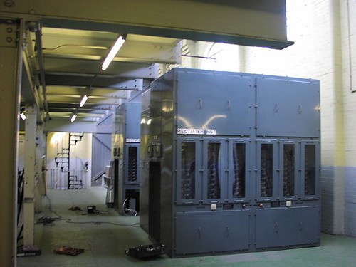
Traction Rectifiers in Queensland Road Sub-station, Northern City Line.
Control of circuit breakers
The four high speed circuit breakers in the TPH at Poole Street and the two high speed circuit breakers at Queensland Road and the two high speed circuit breakers at Finsbury Circus are controlled from local Slave Relay Units. In each case, the final interface to the high speed circuit breaker from the Slave Relay Unit is a BR930 relay contact which opens to discharge the traction section. This contact operates a D2600 interface relay (produced by Signature Industries, formerly Clifford and Snell) within the high speed circuit breaker from a nominal 50 volt d.c. supply provided by the d.c. switchboard. The Slave Relay Units are controlled over telecommunications cable from the Tunnel Telephone Cubicle at Finsbury Park.
Tunnel Telephone/Signal Post Telephone Tunnel Wires
In tunnel sections of the system, a Tunnel Telephone system provideds traction discharge and voice communication between the driver and Signaller at Kings Cross. Traction trip and speech is provided over two bare copper alloy wires carried, one above the other, on pairs of porcelain insulators supported on metal brackets fixed to the tunnel wall. The insulators are generally provided every 6 metres along the tunnel so as to keep the wires about 115mm apart. The wires are positioned so as to be accessible by leaning from the driving cab window of a train. The tunnel wires are divided into 20 sections so as to provide each colour light running signal with a dedicated speech circuit to the Signaller.
Trainborne equipment
Portable tunnel telephones are mounted in the cabs of all EMU which work over the line. They incorporate DTMF (Dual Tone Multiple Frequency) calling to the signaller and a means of shorting the circuit so as to discharge the traction supply. Pressing and holding either yellow button automatically sends a short burst of DTMF tone, after which speech is possible. The duplicated pushbutton makes the handset suitable for left-handed and right-handed users. Pressing the red ‘ISOLATE’ button places a low resistance across the tunnel wires, in order to discharge the traction supply. Alternately, Traction current may be discharged by simply 'pinching' together the two tunnel wires.

Tunnel Telephone used by Drivers to discharge traction or talk to the Signaller.
Tunnel Telephone/Signal Post Telephone Equipment Cubicle, Finsbury Park
A 2-metre high enclosed equipment cubicle is provided in the Telecommunications Equipment Room at Finsbury Park, together with a battery-backed power supply providing nominal 24 volt d.c. for the Tunnel Telephone equipment.

Northern City Line Tunnel Telephone system: Equipment Cubicle at Finsbury Park Telecommunications Equipment Room.
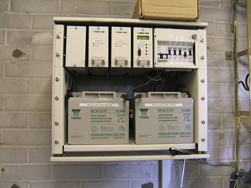
Northern City Line Tunnel Telephone system: Power supply at Finsbury Park Telecommunications Equipment Room.
The main telecommunications cables for the East Coast Main Line pass through a Distribution Frame in the Telecommunications Equipment Room, allowing simple cross-jumpering of the Northern City Line Tunnel Telephone circuits across to pairs leading to the controlling signal box at King's Cross.
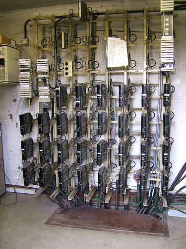
Northern City Line Tunnel Telephone system: Main Distribution Frame at Finsbury Park Telecommunications Equipment Room.
King's Cross Power Signal Box
The control of the Northern City Line was provided from King's Cross Power Signal Box (now planned for closure with control transferred to York Railway Operating Centre). At King's Cross, the Supervisor’s desk had a reset control panel which allowed York ECR to recharge the conductor rails of the Northern City Line. This was controlled from special Reset and Indication cards in the Telecommunications Equipment Room. Signal Post Telephone calls were processed by special SPT cards in the Telecommunications Equipment Room which detected the DTMF call tone and presented to call to Signallers on the main signalling console.
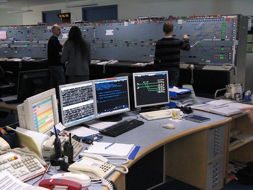
Supervisor's Desk & general view (Photo: Thales).
Related posts on other websites
Although the links worked at the time this post was published, changes made by that website's owner may 'break' the link.
Northern City Line (Wikipedia).
British Rail Class 313 (Wikipedia).
Great Northern and City Railway (Grace's Guide).
110 YEARS OF THE GREAT NORTHERN & CITY (The London Underground Railway Society).
Related posts on this website
London Underground - Traction Power Distribution.
Fourth Rail Electrification.
Electrification Telephone Systems for British Rail.
London Underground and Jan.
Rail Industry Information Day, 2018.
Related photograph albums
Where necessary, clicking on an image above will display an 'uncropped' view or, alternately, pictures may be selected, viewed or downloaded, in various sizes, from the albums listed:-
Northern City Line: 2-Nov-2006.
Kings Cross Power Box.
TTSystem for NCL: Installed System: 21-Oct-2009.
TT System for NCL: Equipment.
TT System for NCL: Testgear: 11-Jun-2009.
On Friday 12th January 2018, I attended the annual RSSB Rail Industry Information Day which was held (outside London for the first time, I think) at the University of Birmingham.
Getting there
I took the first bus from Brewood to Wolverhampton and caught the busy 08:11 Arriva Trains Wales to Birmingham International, getting off at Birmingham New Street. Having some time in hand, I toured the Grand Central shopping area, amazed at the range of food outlets well-patronised by people taking breakfast - coffee shops, juice bars, pizza places, sushi bars, Mexican food, even Korean Street Food! I talked about my reaction to Birmingam's Grand Central in the earlier post here.

Grand Central, Birmingham New Street: Atrium showing retail outlets at both Concourse Level and around the Gallery.
I exited to Stephenson Place to see the temporary terminus of the 'Midland Metro' now that the extension from the original terminus at Snow Hill along Corporation Street to New Street station is, belatedly, in use. A further extension, due to open in 2019, will pass the Town Hall and reach Centenary Square. The rolling stock comprises 21 units of the 'Urbos 3' five-section articulated design built by CAF in Spain. See the Wikipedia article here.
Returning to the station, I was just in time to catch the next Class 323 Electric Multiple Unit on the Cross-City service. The service was taken over by 'West Midlands Trains' on 10-Dec-2017 (as I mentioned in the earlier post A Trip to Merseyside) but, externally, the former 'London Midland' livery is still carried. The Class 323 were built by Hunslet between 1992 and 1995 and, under our crazy arrangements for privatising railways, the trainsets are now owned by Porterbrook which is a 'ROSCO' (rolling stock company). There's a Porterbrook data sheet on the Class 323 here.
The journey only took a few minutes and the University of Birmingham has its own station called, with admirable clarity, 'University' (although the station is equally handy for the huge Queen Elizabeth Hospital). Since I walk slowly these days, it took me 15 or 20 minutes to walk across the large university campus to the venue. The focal point of the university remains the original D-plan grouping of red brick buildings designed by Sir Aston Webb and Ingress Bell built between 1900 and 1909 with its campanile clock tower of tapering square section with a corbelled top stage and lantern, called the 'Joseph Chamberlain Memorial Clock Tower', the 'Chamberlain Clock' or simply 'Old Joe' in honour of the university's first chancellor. There's more on the clock tower in the Wikipedia article here.
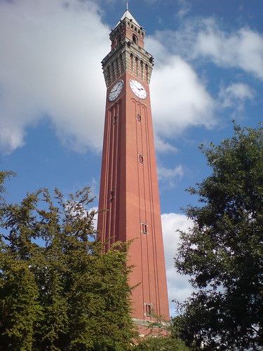
Joseph Chamberlain Memorial Clock, University of Birmingham (Photo: Tomsega, Public Domain).
The initial, unified group of buildings is now surrounded by numerous more modern structures, each of a completely different design reflecting tastes at the time of building.
The venue

Rail Industry Information Day, 2018: Gisbert Kapp Building, University of Birmingham.
The venue was the School of Electronic, Electrical and Control Engineering located in the Gisbert Kapp Building. I had to look up Gisbert Kapp, an Austrian/English electrical engineer born 1852 who held the first Chair of Electrical Engineering at the University of Birmingham from 1904 until his death in 1922. There's a detailed profile in Grace's Guide here.

Gisbert Kapp in 1922 (Photo: Grace's Guide).
The Sponsor
The event was sponsored by the Rail Safety and Standards Board (RSSB), created in 2003 following Railtrack's demise as an independent not-for-profit company limited by guarantee, with a remit to encourage rail research and innovation and creating better links between universities and the rail industry. The University of Birmingham is home to the Birmingham Centre for Railway Research and Education (BCRRE), described here.
The railway industry is now littered with a bewildering array of initiatives and acronyms whose initials were freely used throughout the proceedings. Here are a few:-
RSG (Rail Supply Group)
RDG (Rail Delivery Group)
TLG (Technical Leadership Group)
UKRRIN (UK Rail Research and Innovation Network)
The event
Registration took place on the first floor where refreshments were available in 'The Link', a student Open Learning area closed to students for the day.
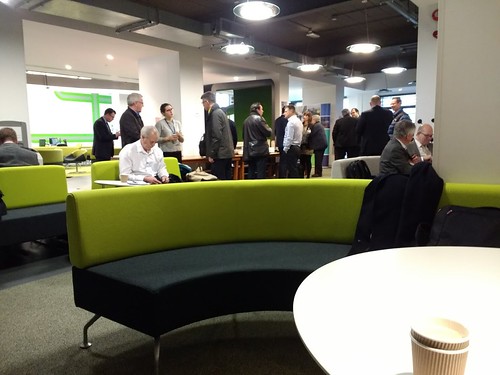 Rail Industry Information Day, 2018: Refreshments in 'The Link'.
At 10:15 we were invited to troop to a large, modern lecture theatre on the ground floor. There were almost 100 attendees, over half from the rail industry. Martin Brennan, Head of European Programmes at RSSB, said that the day would review the Horizon 2020 and Shift2Rail Work Programmes and Collaboration funding opportunities available within 80 billion Euros of funding being provided by the European Union (EU) between 2014 and 2020. More information is available here. Within Horizon 2020, Shift2Rail (S2R) is dedicated to railway research, with more information here.
Professor Clive Roberts [Professor of Railway Systems at the University of Birmingham and Director of the Birmingham Centre for Railway Research and Education (BCRRE)] then gave a "virtual tour" of the Railway Centre of BCRRE, one of three centres in the United Kingdom supporting new innovation in rail transport and part of UKRRIN.
Next, Carlo Borghini who is Executive Director of the Shift2Rail Joint Undertaking updated the meeting on the current programme status and future opportunities.
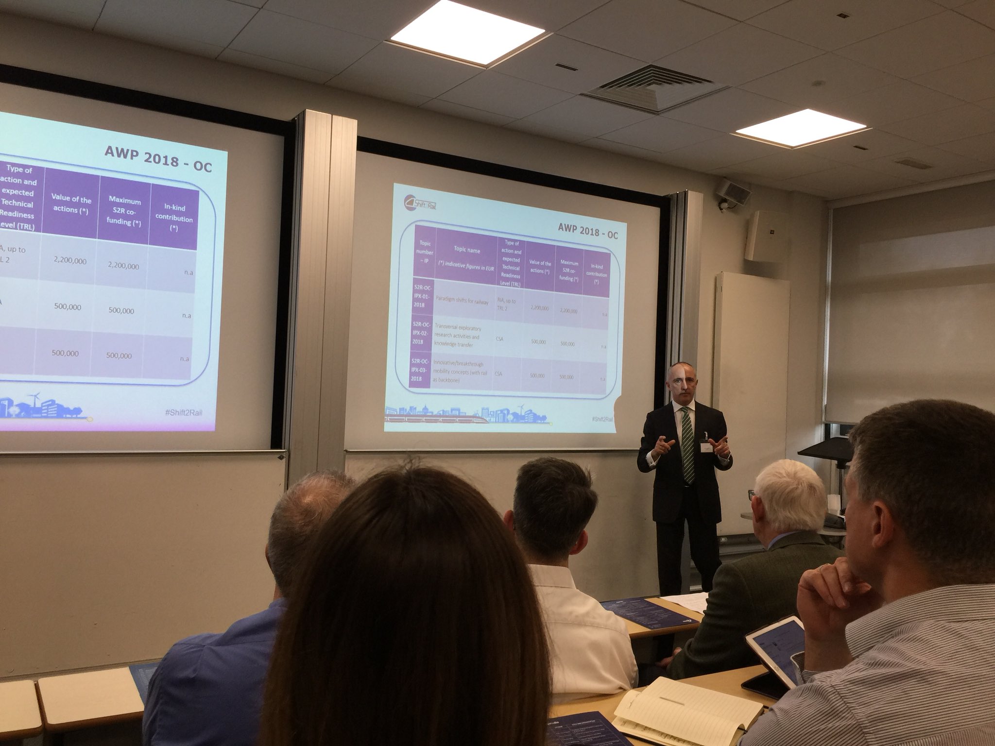
Carlo Borghini addressing Rail Industry Information Day (Photo: Professor Clive Roberts via Twitter).
Louise Mothersole (Horizon 2020 UK National Contact Point for Transport at Innovate UK) explained that the decision of the United Kingdom to leave the European Union did not affect the eligibility of United Kingdom firms seeking to participate in Horizon 2020.
After a coffee break held in The Link, James Hardy talked about RSSB's Rail Technical Strategy. This was followed by a series of 2-minute 'Elevator Pitches' from 12 speakers, after which a buffet lunch was served in 'The Link'.
At 13:45, Martin Brennan described the European Rail Research Advisory Council (ERRAC) which was set up in 2001 to "promote an holistic vision of the European Rail system with all stakeholders" before introducing Professor Simon Iwnicki (Professor of Railway Engineering and Director of the Institute of Railway Research - Huddersfield University) who spoke about participation in Shift2Rail 'Open Call' projects.
Next, Professor Clive Roberts spoke about the S-CODE Project which aims to investigate radically different technology concepts that can be integrated to achieve significantly improved performance for railway Switches and Crossings emphasising successful techniques used in planning this type of project.
A concise explanation of the various funding opportunities under Horizon 2020 and Shift2Rail was given by Louise Mothersole, with an invitation for applicants to contact the National Contact Point for support.
RSSB, in conjunction with Rail Research UK Association, has completed its Rail Technical Strategy Capability Development Plan (RTS CDP). The plan is divided into 12 'Work Packages' to which 'Work Package Owners' have been allocated.

A graphic representing the 12 Work Packages.
Finally, two of the Work Package Owners made short presentations:-
Janine Fountain spoke about Package 02 - Minimal disruption to train service
Karl Butler-Garnham spoke about Package 04 - More value from data
This concluded an interesting day which had given many useful suggestions to prospective applicants.
Railway Centre
As originally planned, the day was to have started with a physical tour of the Railway Centre laboratories but the large number of attendees precluded this, hence the "virtual tour" mentioned above. However, a small group of attendees stayed behind for a tour offered by Doctor Edd Stewart (Lecturer in digital logic and microprocessor systems who also leads on various research projects). An idea of the Research Capability offered by BCRRE can be gained from the website here. Some of the highlights of the tour are outlined below.
A room containing a 14-foot diameter horizontal wheel with a circle of rail on top can be rotated by a 30 kW electric motor to give the effect of a train travelling at 80 km/hour. Chillers can produce freezing conditions in the room, allowing research into railhead de-icing for railways.
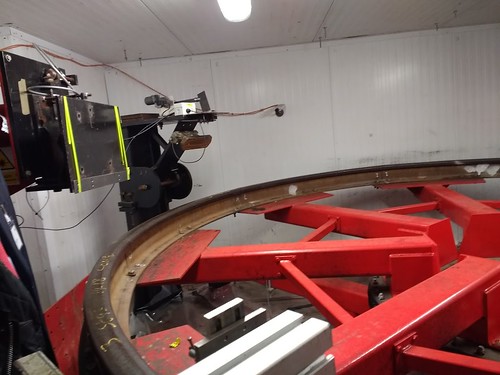
Rail Industry Information Day, 2018: Railhead testing rig.
A well-equipped Railway Control and Operations Simulation room allows research into the next generation of railway traffic management systems.
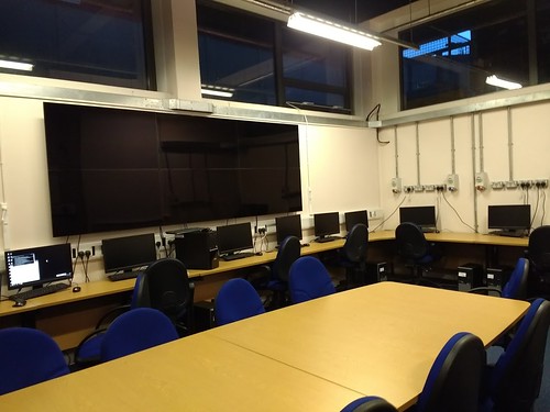
Railway Control and Operations Simulation Room.
In another area, we saw various types of prototype condition monitoring equipment for rolling stock.
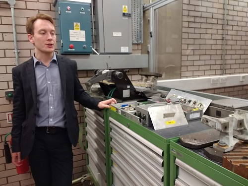
Rail Industry Information Day, 2018: Dr. Edd Stewart with prototype condition monitoring equipment.
We saw the laboratory-based test facility for evaluating and characterising pantograph dynamic loading performance.
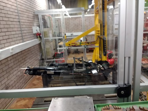
Rail Industry Information Day, 2018: Pantograph test rig.
Nearby, there was a robotic inspection cell for use with railway vehicle wheelsets.
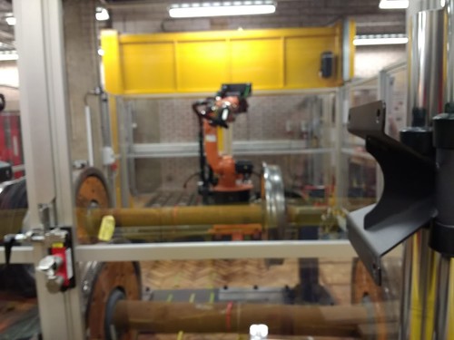
Robotic inspection cell for use with railway vehicle wheelsets.
Another climate chamber held the 'sharp end' of a set of points, allowing the evaluation of point machine performance under varying weather conditions. There was also a small 4-wheel inspection trolley in this chamber, fitted with a robotic arm which can examine the rail head.
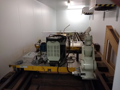
Rail Industry Information Day, 2018: Rail switch test chamber.
A large Motor Generator Set with a programmable load is available for Power Systems and Energy Use research.

Rail Industry Information Day, 2018: Motor Generator Set with a programmable load for Power Systems research.
On our way out, we passed a full-sized cab, which I decided was a Class 717 cab. The Class 700 'Desiro City' are already in use on British Rail. The Class 717 is a variant with end doors for use on the Northern City Line which allows passengers to be evacuated via the Moorgate Tunnel, as is possible with the existing 40-year old Class 313.
Rail Industry Information Day, 2018: Class 717 cab.
Getting back
It only remained to return home by walking back across the darkening Campus, catching a busy Cross-City service to Birmingham New Street, changing to a standing room only Arriva Trains Wales service as far as Wolverhampton and then getting a taxi home (our last bus from Wolverhampton is 17:10!)
Related posts on this website
Rail Research UK Association Annual Conference 2017.
Grand Central and Birmingham New Street Station.
My photograph albums
Where necessary, clicking on an image above will display an 'uncropped' view or, alternately, pictures may be selected, viewed or downloaded, in various sizes, from the albums listed:-
Rail Industry Information Day.


