skip to main |
skip to sidebar
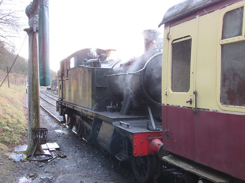
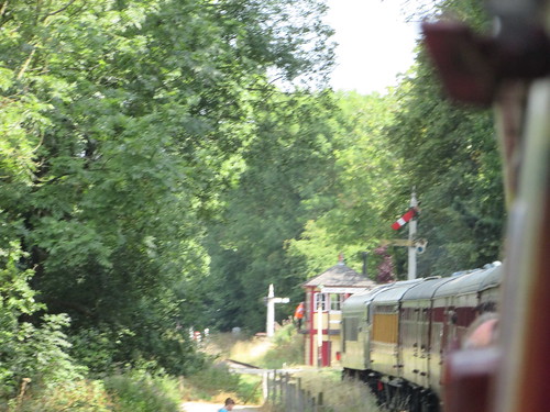
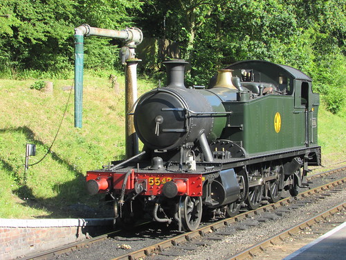
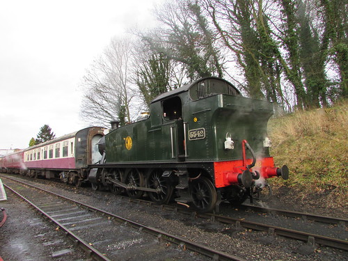
Fig 1: 5542 ready for action on 9-Dec-2017.
The (reproduction) cap badge on my locomens' greasetop reads 'LMS' which I always thought of as my 'spiritual home' (although I was only five when the LMS was absorbed into British Railways on 1st January 1948). However, my period as a volunteer at the then Birmingham Railway Museum at Tyseley gave me an abiding respect for the design of the locomotives of the Great Western Railway and, in particular, for the influence of George Jackson Churchward who was Chief Mechanical Engineer of the GWR from 1902 to 1922.
So, when I set about 'oiling round' on 'Light Prairie' 5542 at Shackerstone shed on 18th August 2018 I was reminded of Churchward's legacy in producing a range of standard locomotive designs which served the Great Western so well. Churchward was ruthless in his pursuit of reliability and efficiency and the sound detail engineering for which the Swindon Works of the Great Western became famous was immediately obvious. However, Churchward was not noted for his aesthetic sense and some of the stylistic features now admired by enthusiasts were due to members of his design team.
On most preserved railways, it is the responsibility of the fireman to perform a series of checks on the boiler before 'lighting-up'. A 'warming fire' had been left in the firebox overnight and, by the time I arrived, the fireman, Jamie, had the boiler just starting to make steam. I made my own check that the single gauge glass (embraced in its plate glass protector to protect enginemen from flying glass should the gauge glass shatter) indicated a safe level of boiler water. Most locomotives have duplicated gauge glasses but the Great Western managed with one, plus 'try cocks' as an alternative method of testing boiler water level. Swindon justified this economy by the rigorous training they gave fireman in the replacement of a failed glass tube in minutes.
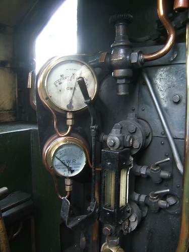
Fig 2: 5542: single Gauge Glass with Protector Note the two Try Cocks on the right of the gauge glass.
I also carried out the essential safety checks - Locomotive in mid-gear, handbrake hard on, regulator fully closed and cylinder drain cocks open. It's also usual to set wooden wheel scotches in front and behind the driving wheel on one side and display a 'Not to be Moved' board in order to prevent any movement until all staff are confirmed out of harm's way.
Sight Feed Lubricator
Moving parts in contact with steam (such as the valves, pistons and regulator valve) require lubrication with a special, compound mineral oil, formulated to retain its properties at high temperature. The sight feed on 5542 is described in a post here (use the back button to return here).
I briefly described oiling 5542 in the earlier post On the Footplate but decided to go into a little more detail this time.
Layout of Valve Gear
The 2-cylinder 'Standard' designs of the Great Western with outside cylinders all feature Stephenson Link motion with four eccentrics mounted on the driving axle between the frames to provide the necessary valve events. With inside cylinder designs, the valves are usually between the frames and can be readily driven from the expansion links via the dieblocks and valve rods. However, where outside cylinders and valves are required, a means must be provided to translate the movement of the dieblocks from inside the frames to outside the frames. Swindon devised a typically rugged arrangement using rocking shafts which is illustrated below.
 Click on the above diagram to enlarge.
Fig 3: Layout of valve gear.
The drawing above shows a tender engine: in the tank engine variant some of the proportions are altered and there's no valve spindle crosshead. The dieblock is attached to an Intermediate Valve Rod, the lower end of which is supported by a swing link. The upper end of the intermediate Valve Rod is attached to the inner of two valve arms attached to the rocking shaft mounted on the framing. The upper end of the intermediate valve rod describes an arc when driving the rocking shaft, necessitating the swing link at the lower end to accommodate this non-linear movement. The outer valve arm also describes an arc, requiring a short valve link connected to the valve spindle to accommodate the non-linear movement.
I usually start my oiling by dealing with any outside motion accessible by walking round at ground level before moving on to less-accessible parts of the locomotive. 5524 has a box for oil bottles and oil feeders mounted underneath the cab just behind the cab footsteps on the driver's (right) side of the locomotive so, having located a suitable feeder and, if necessary, topped it up from the oil bottle of Motion Oil I usually start at the trailing crankpin on the right side and then work around the engine anti-clockwise. It doesn't matter what order oiling points are attended to but some sort of routine is necessary to ensure none are overlooked.
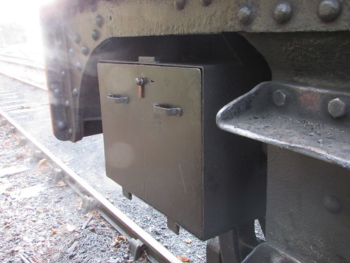
Fig 4: 5524 has a box for oil bottles and oil feeders mounted underneath the cab just behind the cab footsteps on the driver's (right) side of the locomotive.
Coupling rods have a bearing which embraces the crankpin protruding from the coupled wheel. The bearing/crankpin interface is lubricated via a delivery tube by a plug trimming set in the base of a rectangular oil box forming an integral part of the coupling rod. A large cork which prevents ingress of water and dirt is removed to add oil to the reservoir and the check or replace the trimming as necessary.
Moving forward to the right hand driving wheel, matters are more involved. In addition to the crankpin bearing on the leading coupling rod, a rearward extension connects to the trailing coupling rod via the gradient pin. The fluted connecting rod terminates in the massive big end bearing. The sheer size of the crankpin with its broad bearing area and the careful design of the arrangements immediately gives a driver confidence.
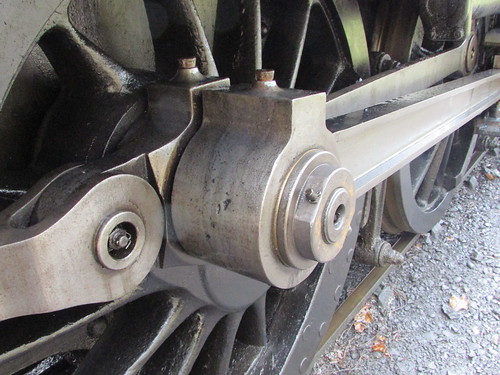
Fig 5: 5542: Right driving crankpin. Leading coupling rod has the bearing for the crankpin and a rearward extension connects to the trailing coupling rod via the gradient pin. The fluted connecting rod terminates in the massive big end bearing.
The oil box at the leading end of the front right coupling rod is frequently hidden by the connecting rod, crosshead or slide bars, depending upon the 'angle' the driving crankpin has stopped at.
The front end of the fluted right connecting rod is provided with a generous oil box (closed with a cork) to provide lubrication to the pivoting joint with the gudgeon pin which secures the connecting rod to the crosshead. However, if the big end of the connecting rod has stopped above the piston centreline, the space above this oilbox is reduced and dealing with this oiling point may have to be deferred.
The crosshead itself slides between two substantial machined slidebars attached between the cylinder block casting at the front and the massive motion bracket positioned rearwards about 2/3 along the slide bars. On the right of 5542, the lower slide bar is lubricated from an oilbox formed into the bottom of the cross head so, if the big end of the connecting rod has stopped below the piston centreline, the space above the crosshead oilbox is reduced and dealing with this oiling point may have to be deferred. The right upper slide bar on 5542 is lubricated from two cast oil pots with tail trimmings attached to the upper face of the slidebar one to the rear of the motion bracket (visible in Fig 6) and one ahead (seen on the left in Fig 7). Both these oil pots deliver oil through oilways to the lower face of the upper slidebar.
The right crosshead is provided with four hex-head bolts (visible in Fig 6 and Fig 8) which attach a drive bracket behind the slide bars for the vacuum pump so that, when the locomotive is in moving, the motion of the crosshead also drives the piston of the vacuum pump. The black-painted vacuum pump body is visible top left in Fig 6 with its piston extending forward and connected to the drive bracket. Fig 8 gives a better view of the vacuum pump drive bracket and its connection to the vacuum pump piston.
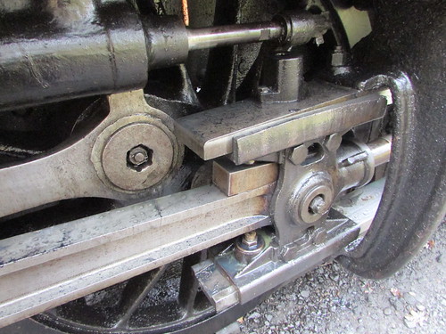
Fig 6: 5542: Right Crosshead near back dead centre.
A further complication in this area is the small oil box closed with a cork to provide lubrication to the connection at the bottom of the right outer valve arm to the rear of the short valve link and a similar oil box formed into the front of the short valve link where it connects to the right valve spindle. This is shown in Fig 7 and, again, in Fig 8 with the engine stopped in a different position.
Finally, Fig 7 also shows a second oil pot mounted on top of the right upper slide bar. In common with some patterns of oil pot, this example is closed by a tabbed flat steel cover, secured by a single screw allowing the cover to rotate so that oil can be added and the tail trimming checked. This oil box delivers oil via a vertical copper pipe to lubricate the right piston rod just to the rear of the piston gland.
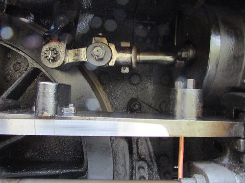
Fig 7: 5542: Front of Upper Slidebar on Right Side, with the Right Crosshead near back dead centre, showing two Oil Pots. At the top, is the outer valve arm of the rocking shaft connected via the short valve link to the valve rod.
For comparison with Fig 6, Fig 8 shows the appearance of the motion when the right crosshead is near front dead centre.
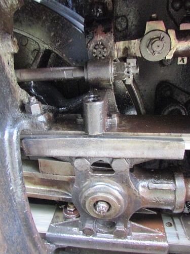
Fig 8: 5542: Right Crosshead near front dead centre, showing drive to the piston of the vacuum pump.
Now we move round the front of the engine to the left side of the engine, remembering to bring the oil feeder, oil bottle (allowing the feeder to be replenished as necessary) and all-important 'wiper' (a rag to remove any surplus oil). Completing the oiling of the outside motion on the left is largely a repetition of the process on the right but this time working from front to back. Because the motion on the left side is a quarter of a turn behind the right, oiling points which were readily accessible on the right may be hard or impossible to reach on the left (or vice-versa) so the driver must keep a careful note of any oiling which has been deferred until the locomotive can be moved.
Fig 9 below shows the left crosshead on 5542. There is no vacuum pump to drive on the left of the locomotive so (on 5542 at least) the left crosshead is a different pattern. Although the left upper slidebar is drilled to mount three oilboxes (like the right), only the leading oilbox feeding the left piston rod is fitted. The upper slidebar is lubricated from an oilbox formed into the top of the crosshead and a second oil box formed into the bottom of the crosshead serves the lower slidebar. The picture shows that the oil box at the leading end of the front left coupling rod is easily accessible but the oilbox at the little end of the left connecting rod is obstructed.
The left outer valve arm and short valve link (not illustrated) also require attention.
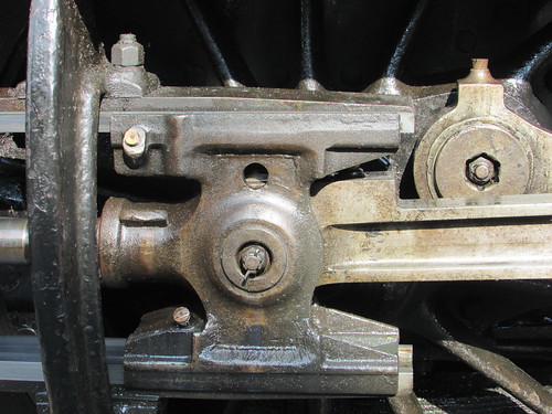
Fig 9: Left Crosshead.
Fig 10 shows the left driving crankpin with oil reservoir on the connecting rod big end, oil reservoir on the coupling rod and oil hole in the gradient pin.
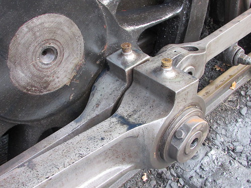
Fig 10: 5542: Left driving crankpin. Leading coupling rod has the bearing for the crankpin and a rearward extension connects to the trailing coupling rod via the gradient pin. The fluted connecting rod terminates in the big end bearing.
I've included a picture of a sister engine (4588) with connecting rods removed to show the size of driving crankpin necessary to transmit the power of each cylinder to the three associated coupled wheels. Removal of connecting rods was usually done where a 'dead' engine had to be taken a long distance. Each crosshead was wedged in a suitable position during the journey so that the pistons, piston rod and crosshead did not move and thus didn't require oiling.
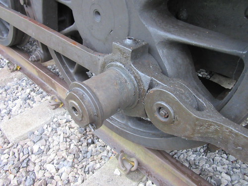
Fig 11: 4588 showing left driving crankpin with connecting rod removed pictured whilst in store at Peak Rail.
Once the oil reservoir on the rear of the left trailing coupling rod is done, that's the easy oiling finished. In the the conclusion of this article here I describe attending to the inside motion by descending into the pit underneath the engine and clambering up underneath the boiler and other necessary oiling.
Related posts on this website
Preparing 5542 (part 2).
To see all my posts about the Battlefield Line, select Label 'Battlefield Line' or click here.
My photograph albums
Where necessary, clicking on an image above will display an 'uncropped' view or, alternately, pictures may be selected, viewed or downloaded, in various sizes, from the albums listed:-
5542 GWR Locomotive
Battlefield Line, 2017-2018
All my Battlefield Line albums
[Link to part 2 added 6-Aug-2019]
Saturday, 25th August 2018 was the start of the August Bank Holiday Weekend and the Battlefield Line were offering a 'Family Fun Weekend'. The publicity proclaimed:-
Fun for all the family at Market Bosworth Station Goods Yard. Come along and see;
Splat the rat
Plinko
Hook a duck
Ring toss
Bucket toss
Buzz wire
Ten pin bowling
Basket ball
Boxing
Inflatables
Temporary tattoos
Face painting
Story telling.
Win tickets to collect prizes. Trains running between Shackerstone, Market Bosworth and Shenton all weekend. Get on at Shackerstone or Shenton and receive free entry into the event at Market Bosworth.
Events of Saturday, 25th August 2018
I was asked to drive 5542 on the Saturday and was pleased when a text arrived saying that Tracy Tye was firing. I arrived at 7.00 a.m. and found 5542 in the shed with the remains of a warming fire still glowing red and almost 20 pounds on the clock. Tracy arrived just after me so we had almost four hours before the first service. A previous mechanical failure had put the back damper out of service until repairs could be carried out so we contented ourselves with using just the front damper to control 'primary air'.
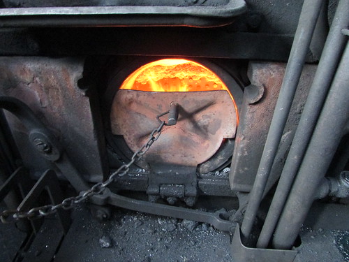
5542 Firehole with Flap plate up.
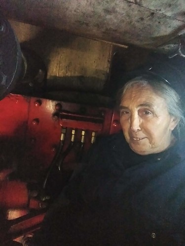
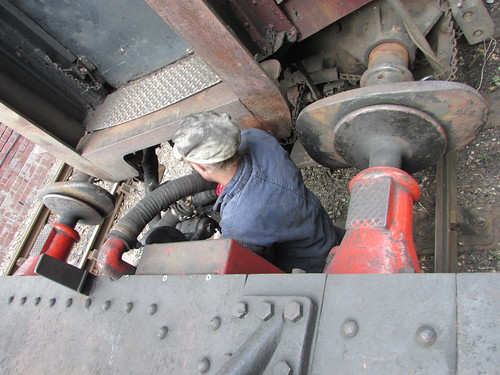
I left Tracy with the fire whilst I plodded my way through the daily 'exam' and 'oiling round'. Although the '55XX' has outside cylinders, the Link Motion to drive the valves and four of the oil boxes feeding coupled axleboxes are between the frames. The picture below shows me sitting on the leading coupled axle facing backwards underneath the boiler, having climbed up from the inspection pit. I probably look happier than I felt.
Battlefield Line 2018: Oiling 5524
Oiling and 'daily exam' got a lot easier when designers started to make locomotives with two outside cylinders and outside motion (usually, not invariably, Walschaert's motion). This lesson seemed to be learned very late in the United Kingdom. I admit that many overseas countries had a more generous loading gauge than us, allowing them to use larger outside cylinders than possible here. And I agree that, within the confines of our loading gauge, very powerful locomotives may need a third or fourth cylinder to be able to generate that power (then transferring the problem to the difficulty of making a boiler which can generate enough steam to feed those cylinders without itself fouling the loading gauge). The contortions necessary to complete oiling on some locomotives certainly favour younger people yet, in the 'old days', footplatemen could be quite old before they attained the seniority and experience to be given, say, a 3-cylinder 'Royal Scot' or 4-cylinder 'Castle' to prepare. According to the Wikipedia article here, the Ancient Greeks first looked into what we now call 'Ergonomics' or 'Human Factors' but it was the American engineer Frederick Winslow Taylor (1856-1915) who first applied the ideas to increasing the productivity of workers in the industrial age.
In the early part of the day, we had some difficulties with steaming and lost a little time. The mantra is "Get it hot and keep it hot" but that's hard to achieve on the sort of diagram we were undertaking. On a long distance express, once the engine is hot, it can be kept that way by adjusting the firing rate to match the demand for steam. The fireman may be able to set an injector fine enough to leave it running and maintain the boiler water level. But our booked timings were as below:-
| Shackerstone Dep |
11.00 |
12.15 |
13.45 |
15.00 |
16.15 |
| Market Bosworth Dep |
11.12 |
12.27 |
13.57 |
15.12 |
16.27 |
| Shenton Arr |
11.20 |
12.35 |
14.05 |
15.20 |
16.35 |
| Shenton Dep |
11.35 |
12.50 |
14.20 |
15.35 |
16.50 |
| Market Bosworth Dep |
11.45 |
13.00 |
14.30 |
15.45 |
17.00 |
| Shackerstone Arr |
11.55 |
13.10 |
14.40 |
15.55 |
17.10 |
Looking at the timings for the first trip (later trips have similar allowances), the engine uses steam for no more than about ten minutes before there's a brief stop at Market Bosworth. Then steam is consumed for less than ten minutes before arriving at Shenton. That's an oversimplification. Leaving Shackerstone, there's a succession of different 'slacks' (speed restrictions) until the top of the bank, then Line Speed (25 m.p.h.) is interrupted by a very short distance with a temporary restriction at 10 m.p.h., then there's a succession of different 'slacks' into and out of Market Bosworth before Line Speed is authorised until the run-in to Shenton where the restriction is 5 m.p.h. Of course, the same speed restrictions apply on the return journey but, with the gradients now reversed, the effect on driving method is different.
Because of the variations in allowable speed, the driver frequently adjusts the regulator (the large handle which lets steam into the cylinders from the boiler) between 'Drifting' (essentially closed but with sufficient steam to ensure adequate lubrication to the pistons and valves) and various 'Open' settings. Alternately, the driver can choose to adjusts the 'Cut-off' (altering the percentage of piston travel for which live steam is admitted to the cylinders). Cut-off is adjusted on the reverser which is a lever (or 'Pole') reverser on 5542.
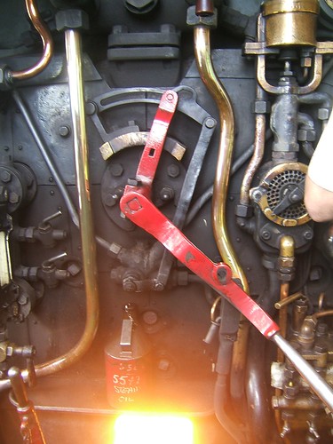
5542: The Regulator Handle in the 'Drifting' position.
So the demand for steam is rapidly changing, requiring close co-operation between driver and fireman to avoid either having insufficient steam to work the train to time or too much resulting in discharge of steam from the safety valves (wasting coal, water and fireman's shovelling efforts). Although the rate of steam generation can be altered by altering the rate at which fuel is added, by control of the dampers ('primary air'), by adjustment of the firedoors ('secondary air') and by adjustment of the artificial draught using the Blower, change does not occur instantly. There's another, rather cryptic, mantra: "Driver's steam - Fireman's steam". That means, when the regulator is open, the fireman should be producing steam at a sufficient rate to keep the driver happy ("Driver's steam") but as soon as the regulator is closed or set to drifting, the steam still being produced is at the disposal of the fireman ("Fireman's steam"). This gives the fireman the chance to put on an injector, replenishing boiler water and the cooling effect tends to preventing wastage of steam from the safety valves.
There are a number of posts in this blog which discuss various aspects of the footplatemens' art. Most of these can be found in the series of articles labelled 'MIC' which are briefly listed in an index here.
On arrival at Shenton, the fireman is then preoccupied with uncoupling the locomotive, working the hand points to let 5542 from the headshunt onto the run-round and keeping a lookout as the locomotive runs the length of the run round, crosses back onto the running line and sets back onto the train.
Battlefield Line: Family Fun Weekend August 2018: Tracy uncoupling 5542 from our train.
Finally, the fireman has to couple the locomotive back onto the train. Just 15 minutes is allowed for all these activities, for which I've given only a simplified outline. I've not fully described what's involved in uncoupling and coupling, with heavy screw couplings to manipulate off and onto drawhooks, vacuum hoses to be wrestled apart and connected-up and, in the steam heating season, steam heating hoses to be dealt with. There's a more detailed description of attaching a locomotive to passenger coaches in the post here and more information about screw couplings in the post The Role of the Shunter (2).
On days when a third person is rostered on the footplate (usually a Cleaner gaining practical experience), the workload can be shared but, on the day being described, there was only Tracy and the writer on the footplate: all other available 'bodies' were at Market Bosworth helping with the 'Family Fun Weekend'.
Each time the train returns to Shackerstone, the workload is even worse. Once again, the fireman is preoccupied with uncoupling the locomotive, working the hand points to let 5542 cross to the other platform road and keeping a lookout as the locomotive runs through the station and crosses onto the running line and then sets back towards it train. But, before attaching to the train for the next run, the locomotive water supply is normally replenished at the water column just south of platform 2, as described in the section 'Water Supply' in the post 5542 at the Battlefield Line.
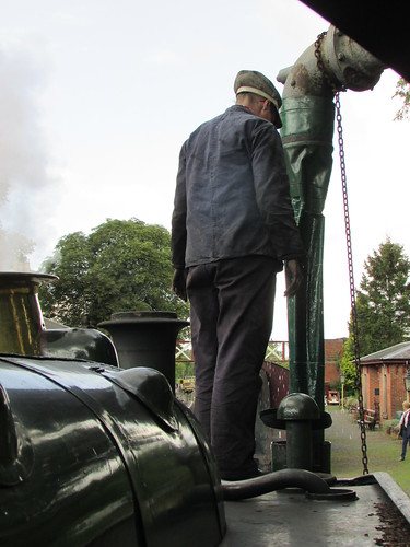
Battlefield Line: Family Fun Weekend August 2018: Watering at Shackerstone. The safety valves are 'sizzling' in traditional Great Western fashion.
Twenty minutes are generally allowed for running round and taking water at Shackerstone. However, in a timetable innovation introduced, I think, this year in between the second and third trains, there's a luxurious 35 minutes allowed for running round and watering, which gave us a chance to depart 'Right Time'.
The fireman is always trying to anticipate the effect of adding fuel because, as stated above, changes in the rate of steam generation do not occur instantly. This is particularly the case when using coals with low volatile content, like the opencast 'Welsh' we were using (which I talked about in the section 'Coal Supply' in the post 5542 at the Battlefield Line).
Both Tracey and I quickly became dirty from the coal dust flying around, although Tracy frequently used the coal watering hose ('pep pipe') in an attempt to lay the dust. One elderly group at Shenton seated outside the Buffet burst out laughing at my appearance - I certainly did look like a refugee from the 'Black and White Minstrels'. A couple of lady passengers at Shackerstone commented (favourably) that we were fielding an all-lady crew. One man, noting the difference in our ages, asked if we were Mother and Daughter. Any parent would be proud to have the independent and determined Tracy as a daughter but I admitted that we were not related.
The weather was hot all day apart from two short, sharp periods of rain. We were gratified at the number of passengers, and we were frequently delayed at Market Bosworth, the base for the entertainments, because of the number of passengers joining and leaving the train. Dave N. was the train Guard and his help in changing the loco lamps at each end of the line and taking water at Shackerstone was particularly welcome.
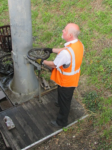
Battlefield Line: Family Fun Weekend August 2018. The Guard, Dave N. assisting with taking water.
Tracy and I completed our shift tired, dirty but pleased the day had been a commercial success. The following day (Sunday) suffered indifferent weather, depressing visitor numbers, but on Bank Holiday Monday, the weather improved and large numbers of visitors arrived to complete an excellent event.
Related posts on this website
To see all my posts about the Battlefield Line, select Label 'Battlefield Line' or click here.
My photograph albums
Where necessary, clicking on an image above will display an 'uncropped' view or, alternately, pictures may be selected, viewed or downloaded, in various sizes, from the albums listed:-
5542 GWR Locomotive
Battlefield Line, 2017-2018
All my Battlefield Line albums
The '1940s Weekends' are popular features at many preserved railways and it is an important weekend at Peak Rail. Directly opposite the station platform at Rowsley is a large wooded area which is used on each day for a dramatic battle re-enactment which can be watched in safety by visitors from the station platform once the service train has been despatched to Matlock.
The Event on Sunday, 5th August 2018
2018 had enjoyed a long, hot summer and the 5th August was no exception. I was rostered as steam driver with Dave P. as fireman and Colin D. as cleaner on the second day of the two-day event. As I walked to the Locomotive Shed to sign-on it was still quiet. Our 7-coach train was waiting in the platform and a large, white marquee has been erected adjacent to the north end of the platform for the wartime entertainments.
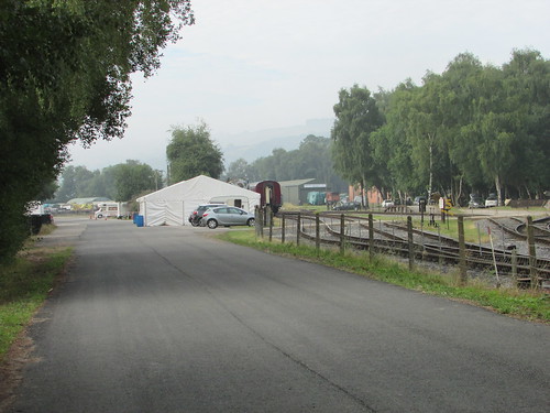
Peak Rail 1940s Weekend 2018: Looking south towards Rowsley Station on my arrival.
As usual, the wooded area opposite the station had become a series of military encampments and the re-enactors were starting to emerge from their tented accommodation and prepare breakfast over a number of campfires.
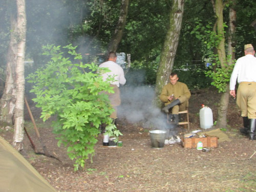
Peak Rail 1940s Weekend 2018: Breakfast in camp.
As well as the encampments and a number of replica military vehicles, there was an imposing replica Messerschmitt Bf109e (which, I later learned, incorporated some parts of a genuine wartime aircraft).
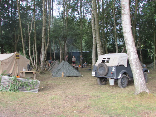
Peak Rail 1940s Weekend 2018: The German Camp.
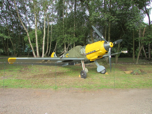
Peak Rail 1940s Weekend 2018: Messerschmitt Bf109e.
Unusually, our locomotive (Austerity tank No. 72) had been turned to face north and we were to work at the north end of the train, top and tailing with 'Penyghent' at the south end. This seems to be the practice for the '1940s Weekend' and I presume it's to avoid the continuous rumble of a large diesel engine standing right outside the marquee when the performers are singing and dancing. It makes a nice change to be 'the other way round' (as long as the driver can remember the 'stop marks' for bringing the train to a stand at Darley Dale and Rowsley).
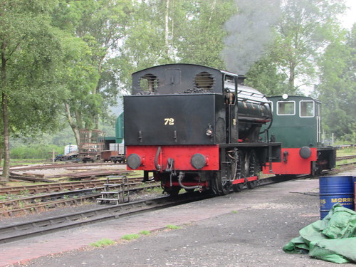
Peak Rail 1940s Weekend 2018: No. 72 'brewing-up' on the outside pit.
Dave and Colin had the engine warming-up nicely, so I was able to concentrate on oiling-round and carrying out the daily exam. Later, the crew arrived to prepare 'Penyghent'. Both locomotives moved across to the station and coupled onto the 7-coach train. Of course, on the journey to Matlock, No. 72 was "tail-end Charlie" so we'd have little to do. Departures are often a bit late, waiting for booked parties to arrive but I think our first train was close to 'right time'. 'Penyghent' made the booked stop at Darley Dale and then continued to Matlock Town.
Peak Rail 1940s Weekend 2018: Darley Dale Up Platform.
At Matlock Town, 'Penyghent' surrendered the token to us for the return journey when we would have a chance to do some work. The Guard had given us the load as 385 tons nett - 7 coaches plus Penyghent trying not to do anything unless requested. Gross weight is obtained by adding in the weight of the passengers, around one ton for every 15 passengers.
I talked about train weights and gradients in a post about the '1940s Weekend' in 2013 here and I copy below the gradient diagram from that post.
 Gradient Diagram Ambergate - Bakewell
The initial run from Matlock Town to passing Matlock Riverside is a downgrade at around 1 in 170 which tends to build up speed with very little steam required. We still have a 5 m.p.h. restriction through the loop at Matlock Riverside, so some braking may be required to comply. Once over the River Derwent bridge, the gradient is against you at about 1 in 400 most of the way to Rowsley. Even with 400 tons on the drawbar, that's not much of a challenge for an Austerity tank at the line speeds allowed and 'first valve' on the regulator will normally suffice. The hardest part is probably stopping gently at Rowsley without overshooting the 'mark' so that water can be taken from the rank wagon at the end of the platform.
There was wartime music coming from the marquee, being enjoyed by a crowd of visitors, many in uniform or period clothing. In addition to soft drinks and light refreshments, there was a licensed bar. Hot food and drink was also available at the cafe on the platform.
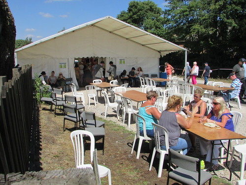
Peak Rail 1940s Weekend 2018: The marquee and outside seating area.
Lots of cars were entering the site and the large car park by the station was rapidly filling up, keeping the marshals helping with parking busy. We made our second round trip, returning to Rowsley to find even more people. At one point, I could see three National Holidays coaches dropping their passengers, turning and parking.
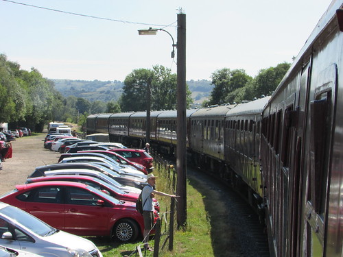
Peak Rail 1940s Weekend 2018: 'Penyghent' sets off from Rowsley with the third service.
By the time we returned on the third round trip, we were quite warm. I usually sport a 'tin helmet' to give a sense of period but it was quite uncomfortable in the warm weather. Dave relaxed on the platform for a while before the fourth departure.
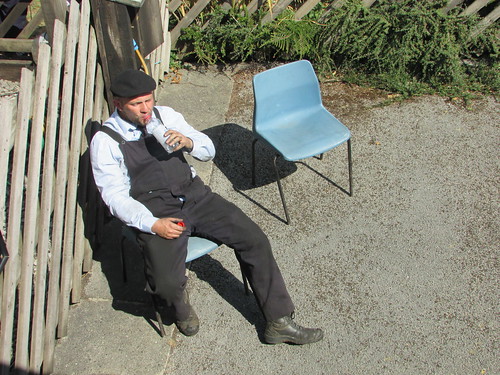
Peak Rail 1940s Weekend 2018: Dave takes hydration prior to the fourth departure.
By the time we left, the platform was packed with visitors, not travelling this time but trying to secure good positions for watching the battle re-enactment which would commence a little later. Well, I can't tell you what happened this year but from previous experience, I know the carefully-constructed displays are well choreographed and usually exciting, with plenty of pyrotechnics.
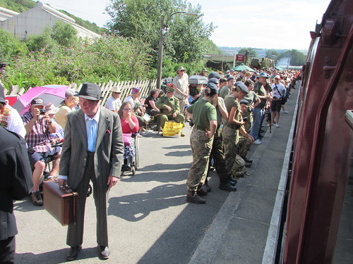
Peak Rail 1940s Weekend 2018: Visitors waiting for the battle re-enactment to commence
Until our line was extended to Matlock Town, our terminus was Matlock Riverside, now rarely used. The vandalised platform shelter has been replaced but not repainted.
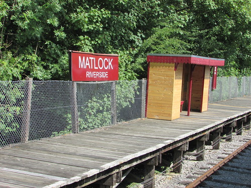
Peak Rail 1940s Weekend 2018: Matlock Riverside. The vandalised shelter has been rebuilt but not repainted.
At Matlock Town, Dave collected the token from Gordon, ready for our departure. On the skyline, Riber Castle still dominates the view. It was built as a family home by a successful industrialist in 1862 but, more recently, has had a chequered history. I think the latest initiative is conversion to flats but I'm not sure of the current status. There's a Wikipedia article here.
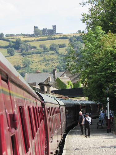
Peak Rail 1940s Weekend 2018: Dave collects the token from Gordon prior our departure to Rowsley.
We made another uneventful trip to Rowsley where the mock battle had finished and many visitors were starting to leave. Just one final round trip remained. At Church Lane, I watched the signalman preparing to collect the Rowsley-Church Lane single line token. Church Lane to Darley Dale is now double track with Absolute Block signalling so no token is required but leaving Darley Dale a token is required for the single line section from Darley Dale to Matlock Town.
Peak Rail 1940s Weekend 2018: 'Penyghent' approaching Church Lane Crossing box. The signalman is on the landing, ready to receive the Rowsley-Church Lane token.
Back at Rowsley, many of the re-enactors were packing up to leave. I hope they had an enjoyable weekend: as we disposed No. 72, Dave, Colin and I certainly agreed we'd had a good day.
The Event in previous years
Peak Rail first ran this event in 2006 and it's proved very popular.
Peak Rail 1940s Weekend, 2017 (article with link to pictures).
Peak Rail 1940s Weekend, 2016 (article with link to pictures).
Peak Rail 1940s Weekend, 2015 (article with link to pictures).
2014 event (pictures only).
2013 event (article with link to pictures).
2012 event (article with link to pictures).
2009 event (article with link to pictures).
2008 event (article with link to pictures).
2007 event (pictures only).
2006 event (pictures only).
To see all my posts about Peak Rail, select Label 'Peak Rail' or click here.
My pictures
Where necessary, clicking on an image above will display an 'uncropped' view or, alternately, pictures from may be selected, viewed or downloaded, in various sizes, from the albums listed:-
Peak Rail 1940s Weekend 2018.
No. 72 - Austerity Tank.
All my Peak Rail albums.
Shackerstone Station: Saturday, 30th June 2018
In 2018, 5542 returned to Shackerstone just after Easter following scheduled repairs at the South Devon Railway. My first driving 'turn' after the locomotive's return was a 'Fish and Chip Evening Special on Saturday, 9th June 2018 (described here) then I did a full day on Saturday, 23rd June 2018 when we had a 'Silver' Footplate Experience course prior to the service trains. A week later I was back again. You might imagine that driving the same locomotive on the same stretch of line a number of times would become boring. It never seems so to me - every trip is a little different.
Events of Saturday, 30th June 2018
In what struck me as a neat inversion of what had happened on the 9th June (when Carl was driver during the day and I took over for the evening service), this time I was driver for the five service trains during the day then, after watering the locomotive, I handed it over to Carl who was taking the evening round trip which, this time, was a Murder Mystery Dining train.
There was no Driving Experience Course prior to the first service at 11.00 a.m. so signing-on for Preparation duties did not have to be too early. But it's always helpful to have time on your side during preparation as the crew never know what may happen. Unusually, the married couple of Rod and Tracy Tye (both experienced footplate crew) were rostered as fireman on a 'buy one, get one free' basis so we were not under undue pressure.
On preserved lines, the driver and fireman sometimes have a safety-qualified trainee rostered as a 'Cleaner', both to learn about firing and boiler management and also assist in other tasks although this was not the case on the 30th. This practice is an echo of the old days when cleaners were given occasional trips on the footplate to learn the essential practical skills. Throughout their careers, footplatemen were helped to make progress in acquiring the necessary technical knowledge and familiarity with the Rule Book by attending Mutual Improvement Classes, briefly described here. A section of this blog (labelled 'MIC') has technical information of the sort which was formerly imparted in Mutual Improvement Classes. You can find all the posts labelled 'MIC' here or find a list of these posts (not always up-to-date) here.
Preparation
The term 'Preparation' covers both Driver's and Fireman's duties in getting a locomotive ready for traffic. In general, the Driver is responsible for the daily examination of the locomotive and 'oiling round' whilst the Fireman concentrates on raising steam but ideally the crew work together as a team to ensure that all the tasks are carried out efficiently. Proper attention to raising steam, oiling and the 'daily exam' helps to prevent failures 'on the road' later. There are a couple of posts in this blog dedicated to 'Preparation' activities on 'Austerity' tank engines:-
Driving Turn at Peak Rail - Part One: Preparation
Preparation of Locomotive 'Sapper'
However, because of its importance, I tend to bang on regularly about Preparation in other posts as well.
Boiler Pressure
Great Western firemen were taught to keep the boiler pressure at the 'sizzling point', just below the red line (200 p.s.i. on 5542), as I mentioned in an earlier post:-
The Great Western were never seduced by the attractions of Ross Pop safety valves and always used their version of the early Ramsbottom design. This lets you bring the boiler pressure close to the blowing-off point with just a wisp of steam continuously escaping from the safety valves, in true Great Western fashion, rather than having the intermittent wasteful (and often noisy) discharge typical of Ross Pop safety valves. It was a point of honour amongst Great Western fireman to 'balance' the boiler with the valves just 'fizzing' to indicate to your driver (and everybody else) that you were on top of the job. Even when I was at Tyseley Railway Museum, if the pressure gauge was more than 10 pounds below the red line on a Great Western engine, the old-time enginemen would enquire "What's the matter? Won't she steam?".
(Battlefield Line Santa Specials 2011)
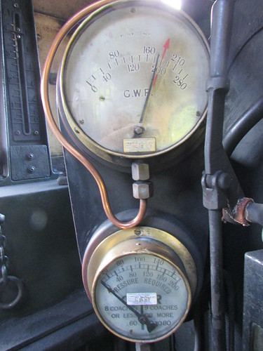
5542 Boiler and carriage warming pressure gauges.
Water Supply
On 5542, water is carried in two side tanks extending back into the cab, coupled by a broad Balance Pipe under the boiler. The '55XX' class had redesigned side tanks, giving a total capacity of 1300 gallons. The front of each tank carries a water filler and air vent. Usually, we take water at the column at Shackerstone (shown in the picture at the top of this post) after each round trip. Whilst running out of steam on a trip is embarrassing, at least the situation can be improved with time. But running out of water leaves the crew with no alternative but to 'throw out the fire' and totally disable the locomotive. Swindon provided their products with float-type water gauges and a tapered column rises above the fireman's side water tank in the cab indicating total water remaining in both Feet and Gallons.
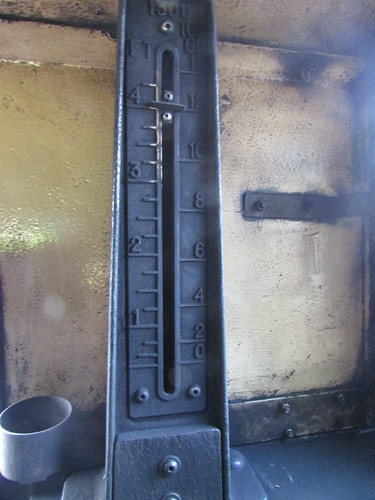
5542 Water Gauge.
Although a full tank (1300 gallons) allows at least two round trips at Shackerstone, the possibility of the float gauge becoming stuck and giving a misleading reading or unexpected delays occuring, encourages crews to regularly take water.
Coal Supply
Coal is carried in a bunker behind the cab. The '55XX' class had a redesigned bunker with a 'bulge' or extension at the top to increase capacity.
Battlefield Line 'Santa' trains 9-Dec-2017: Last 'Classic' train of the day ready to leave Shackerstone. Note the bunker extension.
Great Western locomotive boilers were designed to use Welsh Dry Steam Coal, softer than anthracite with relatively low volatile content meaning the fuel was fairly slow to initially produce heat but, once going, sustained that heat longer as each individual lump swelled and opened up, giving the appearance of a cauliflower head. Competing railways initially believed that the use of 'Welsh' accounted for the superior performance of Great Western engines but the various Locomotive Exchanges, where Great Western locomotives continued to excel using 'bituminous' coals with a much higher volatile content (like the 'Yorkshire Hards'), showed that the real secret was the carefully-proportioned boiler design and the staff training.
Deep mines producing the traditional 'Welsh' have closed but a similar coal, using opencast mining, is currently in use at Shackerstone, I believe from Ffos-y-fran open cast coal mine in East Merthyr. It has many of the desirable features of traditional 'Welsh' but doesn't seem quite as good as the deep-mined Welsh I remember from my time at Birmingham Railway Museum. Any soft, Welsh coal is 'friable' and breaks up into dust readily. It's usually quoted as the reason the Great Western stayed with hand-coaling of locomotive tenders using men tipping skips of coal on a coal stage rather than investing in automated plant as widely used on other railways.
Events of Saturday, 21st July 2018: Diesel Substitution
2018 distinguished itself by providing a long, hot summer. With an absence of rain and farmers not yet having harvested, a number of preserved railways had to temporarily cancel steam operations because of the risk of setting fire to crops. The Battlefield Line was no exception and, on a number of dates, the Diesel Multiple Unit (DMU) replaced 5542. I'd been booked on 5542 for Saturday, 21st July, which was one of the cancelled steam days, so ended up with another DMU driving turn, which prompted the latest post here about DMUs. Following a period of cooler weather with rain, steam operations were able to resume.
Events of Saturday, 18th August 2018
I arrived at Shackerstone shed to find that Jamie, who was firing, already had matters well in hand and he was filling the Sight Feed Lubricator with steam oil.
Sight Feed Lubricator
Moving parts in contact with steam (such as the valves, pistons and regulator valve) require lubrication with a special, compound mineral oil, formulated to retain its properties at high temperature. Before mechanical lubricators became common, sight feed (or hydrostatic) lubricators were often used for this purpose and Swindon developed a range of excellent lubricators. Whereas many railways left the management of these lubricators to the fireman, the Great Western placed the Sight Feed Lubricator in front of the driver. Through training and the issue of circulars, Swindon ensured that drivers understood the method of operation and the importance of the Sight Feed Lubricator. A copy of Great Western Circular 5801 issued in November 1937 by C.B. Collett can be accessed (and downloaded) here.
5542 has the Triple Sight Feed Lubricator with 4 pint oil capacity. Steam from the boiler is condensed in two coiled tubes mounted in the roof of the cab (if one fails in traffic, it can be isolated and running can continue using the second coil).
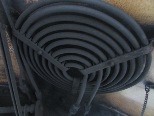
Dual condenser coils for the Sight Feed Lubricator mounted in cab roof of 5542.
The lubricator itself is bolted on the boiler backhead, in front of the driver. The body of the lubricator is filled with steam oil and, when the main cock is opened, water from the condenser displaces oil through the main gallery and, when individual nipple valves are opened from the gallery, droplets of oil form inside the sight glasses, detach and are carried through oil lines to the front end. One of the two left hand glasses (as selected by a 3-position lever on top of the lubricator) serves the valves and cylinders, the one on the right (controlled by a distinctive knob) feeds the slide valve regulator in the smokebox. For more information, refer to the Great Western Circular linked above.
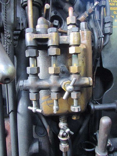
5542 Sight Feed Lubricator.
Jamie also added steam oil to the small oil cup on the feed pipe to the steam brake, to discourage the piston in the brake cylinder from sticking.
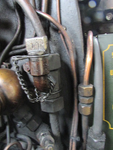
5542: Oil cup for feed pipe to steam brake.
In traffic
During the day, Jamie and I operated five round trips with a four coach train. The weather was hot, the footplate of 5524 hotter (even with the cab roof slid open). There were quite good passenger numbers and we both agreed we'd had a good day, although we were both dirty from the coal dust flying around and tired by the end of service
Related posts on this website
To see all my posts about the Battlefield Line, select Label 'Battlefield Line' or click here.
My photograph albums
Where necessary, clicking on an image above will display an 'uncropped' view or, alternately, pictures may be selected, viewed or downloaded, in various sizes, from the albums listed:-
5542 GWR Locomotive
Battlefield Line, 2017-2018
All my Battlefield Line albums
This is a list of the occasional posts I've written about a group of related locomotive classes, a particular class or, occasionally, just one locomotive in a class. Sometimes, the profile is numbered, sometimes there's just a verbal description.
Posts are listed in reverse date-of-posting order but, just to confuse, each post describes events any time in the history of the locomotive. Alternately, selecting 'Loco-profile' in the list of 'Labels to select a blog topic' will find all my locomotive profile posts (again, in reverse date-of-posting order).
Another way of searching for posts about a particular locomotive or class is to put a search word or phrase into the Search Box in the page header (with the magnifying glass symbol) because a lot of posts which talk about specific classes or engines haven't been called 'Profiles'.
Loco Profile: D.C. Electric Locomotives in the former Soviet Union 26-Nov-2019
Dugald Drummond and the 'T9' - Historical Background (10) 14-Apr-2017
G.W.R. 0-6-0PT 'Pannier' tank locomotives (9) 5-Jan-2016
The 'Austerity' 0-6-0ST locomotive (8) 27-Oct-2015
Loco-profile 7: 'Sapper' 0-6-0ST 16-Jan-2015
Loco-profile 6: 'Planet' replica 13-Nov-2013
Loco-profile No. 5: The Russian 'E' class 0-10-0 1-Jan-2013
Loco-profile 4: Russian 'FD20' class 2-10-2 24-Aug-2012
Loco-profile 3: Russian 'FDp20' class 2-8-4 24-Aug-2012
Loco-profile 2: Russian 'YeA' Class 17-Aug-2012
Loco-profile 1: "Lion" 1-Jan-2010
[List re-ordered: 4-Sep-2018, updated 19-Dec-2019]
At the beginning of October 2014, in the post The Cheshire Lines Committee, I wrote about the history of that joint railway and, in the section 'THE CLC ROUTES TODAY', I outlined what remains of these lines. That prompted me to make a trip, on 4th October 2014, travelling on the Chester-Manchester and Manchester-Liverpool routes of the former C.L.C. That trip is described here. In turn, that provoked a post about the mechanical signalling arrangements which had largely prevailed in the 1950s (here).
In July 2018, I'd arranged to visit a friend in Altrincham and decided that I'd travel there the 'long way round' (Wolverhampton-Crewe, Crewe-Chester, then Chester-Altrincham on the former C.L.C. line) to see what changes had occurred since that earlier trip described here.
Events of Tuesday, 24th July 2018
I started off on the first bus into Wolverhampton. When I discovered just how much a walk-on rail ticket from Wolverhampton to Altrincham would cost travelling before 09:30, the station staff nearly had to summon medical assistance for me but, gritting my teeth, I concluded the transaction and boarded the next Liverpool service as far as Crewe.
Whilst waiting for the diesel multiple unit shuttle to arrive from Chester, I took more pictures of the polychrome brickwork used in the numerous walls supporting the overall roofing. This use of decoration in otherwise functional building works has fascinated me since I first visited Crewe as a child.
Crewe Station: Polychrome brick wall supporting the overall roofing on platform 11.
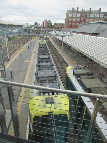
The Liverpool train which had brought me from Wolverhampton departed, then a London-bound 'Pendolino' quietly slipped away from platform 6. Later a Cardiff service from Manchester paused for a minute or two in platform 6. Shortly afterwards platform 6 was re-occupied by a 'Pendolino' bound for Manchester. An Electric Multiple Unit which had been waiting north of the station on the Up Liverpool finally sneaked across the complexities of Crewe North Junction to stable in platform 12. As it passed my vantage point, I confirmed my suspicion that this unit was empty stock. The overall impression was how quiet the station remained most of the time, compared with my recollections from steam days. Even when there were train movements, since most were electric, there wasn't much noise.
There was a fair crowd of travellers on bay platform 9 waiting for the arrival from Chester but, just before the train arrived, the public address announced a platform alteration to the next platform across, bay 10, resulting in a mass exodus as people moved to the new platform. By the time everyone had boarded, the 2-car set was full and we immediately set off for Chester where we were routed into bay platform 1.
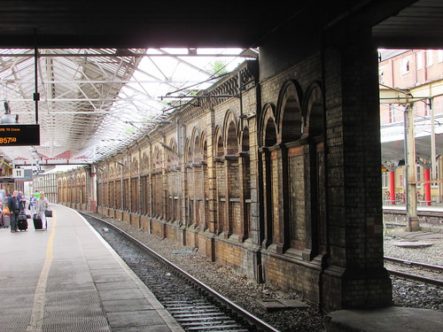
The Chester and Holyhead Railway provided Chester Station with an imposing set of buildings, now very hacked-about after years of adaptations but still, I think, impressive. For instance, even the stairs for the station footbridge are in brick with carved stone detailing.
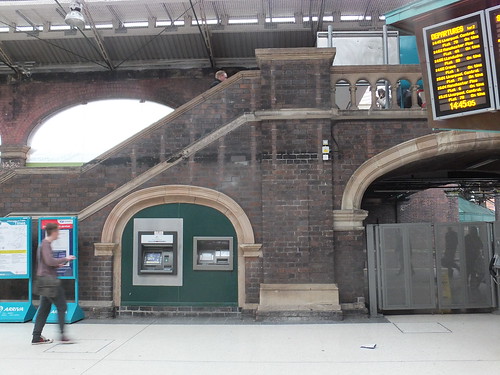
Chester: Original arches and brick and stone stairs adjacent to entrance concourse.
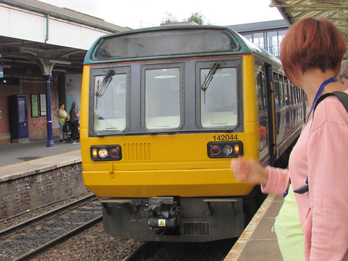
There was time for a few more pictures before I boarded the Class 142 2-car 'Pacer' in bay 6 which would take me to Altrincham. The hourly service from Chester to Manchester via Northwich seemed little changed since my previous trip and still uses 'Pacers'. I've commented before that I'm not a fan of these elderly 4-wheeled monstrosities but my train bowled along gamely with the underfloor bus engines working hard and finally deposited me in Altrincham about right time in just under an hour from leaving Chester.
I only noticed minor changes in the stations and signalling arrangements. Colour light signals prevailed from Chester with its unappealing Power Signal Box, past Mickle Trafford Junction signal box towards Greenbank signal box (both British Railways 'standard' designs).
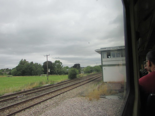
CLC from Chester: Mickle Trafford signal box from a train on the single line to Mouldsworth.
Just before Greenbank, we crossed over the electrified West Coast Main Line. Although the London and North Western manual box at Hartford Junction, a little to the north is long gone, the junction itself remains in a modified form, with a chord which joins the C.L.C. at Greenbank.
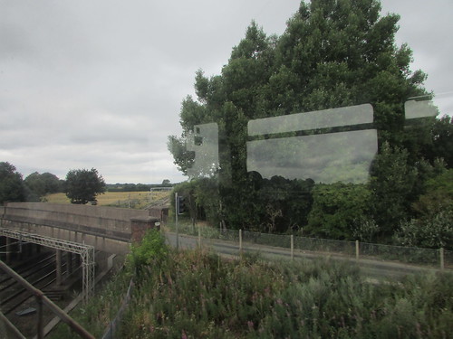
CLC from Chester: Crossing the West Coast Main Line, view looking north.
I noticed that Greenbank station (and probably others) had a different pattern of automatic ticket machine from that in use in 2014. I was glad to see that the Up platform at Northwich retains the extensive range of station buildings with its elaborate platform canopy.
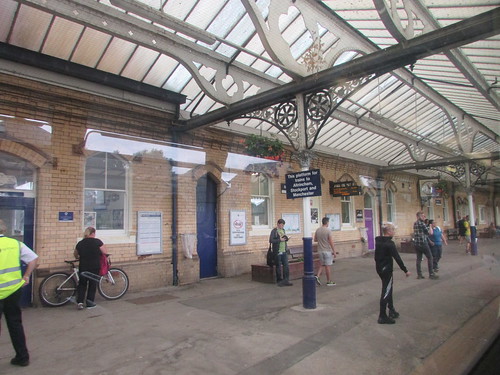
CLC from Chester: Northwich station Up platform.
Lostock Gralam Up platform has one of the dreadful 'bus shelters' plus a modern station nameboard with the interesting invitation:-
Take the Train
Walk the Canal
Visit the Lion Salt Works
The Lion Salt Works is now a museum, operated by West Cheshire Museums, illustrating the open-pan method of salt production. At least Plumley station retains its simple C.L.C. platform shelter, with patterned brickwork.
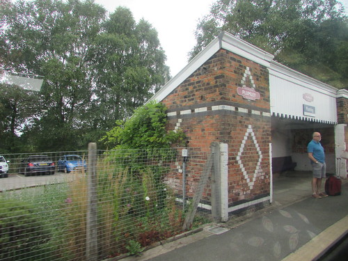 Plumley station: C.L.C. shelter on Up platform.
We crossed over the M6 motorway, with its inevitable road works on the southbound carriageways and made our stop at Knutsford where the wide Up platform has an attractive canopy with cast iron framework and wooden panels in herringbone pattern.
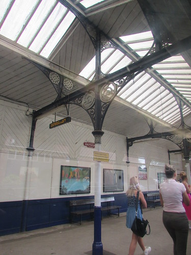
CLC from Chester: Knutsford station Up platform.
My train stopped at Mobberley, Ashley and Hale before I left the train at Altrincham, right time at 10:59.

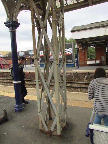
CLC from Chester: Altrincham station platform 3 with Class 142 about to depart for Stockport and Manchester Piccadilly.
Returning home
Late afternoon, I was back at Altrincham station, now called Altrincham Interchange. In addition to being served by the Chester - Manchester service, it is now the terminus of one of the Manchester Metrolink Lines and a bus terminus is incorporated.

Altrincham Interchange: Modern concourse. The original brick station building can be see left background.
The first railway serving Altrincham was started in 1845 as the Manchester South Junction and Altrincham Railway (MSJ&AR) outlined on Wikipedia here. The expansion of Manchester and the increasing importance of Altrincham as a commuter destination lead to the line being electrified at 1500 volts d.c. in 1931. When the Electric Multiple Units (EMU) became life-expired, British Rail decided to convert the line to 25 kV a.c. and the line re-opened in 1971 using Class 304 EMU. The a.c. service was withdrawn at the end of 1991 to allow the line to be converted, again, this time to 750 volts d.c. and services to Altrincham resumed with modern trams in June 1992 as part of Metrolink. There's an article about these changes in electrification on the Light Rail Transit Association site here.
Altrincham: This overhead Line structure, on platform 2/3, with its riveted construction, apprears to date from the 1931 electrification.
Altrincham: Looking towards the buffer stops on Metrolink platforms 1 & 2, with a 'double tram' on the left and a single tram arriving on the right.
I caught a Chester - Manchester Piccadilly service to Stockport. We were in the afternoon peak, so the miserable 'Pacer' was crowded but I managed to find a seat.
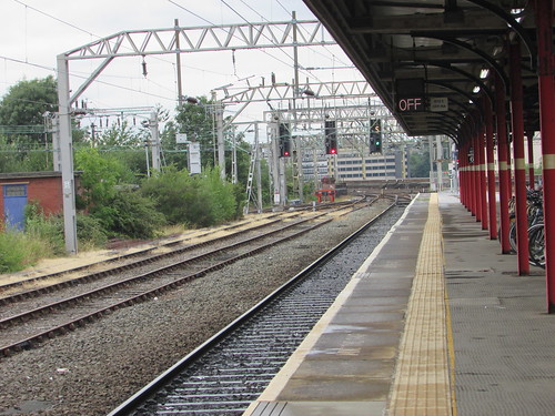
 Altrincham Interchange: Manchester train arriving in platform 3.
It was raining so I couldn't see much on the bumpy, 16-minute journey but I described this interesting route in the post on my earlier trip here.
Stockport: View on arrival from Altrincham. The signal is cleared for the Slow Line which the train from Chester will take to Piccadilly.
I made my way through the subway to platform 2 and, within ten minutes, I was boarding a packed Cross Country 'Voyager' which, after brief stops at Wilmslow and Crewe, deposited me at Stafford from where I took a taxi home. Between Wilmslow and Crewe, I caught a glimpse of the Jodrell Bank Radio Telescope, with its massive dish pointing straight up.
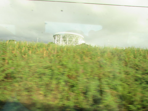
Jodrell Bank Radio Telescope.
My pictures
Where necessary, clicking on an image above will display an 'uncropped' view or, alternately, pictures from may be selected, viewed or downloaded, in various sizes, from one of the albums below. All of these albums were started before the 24th July 2018 and pictures taken on that date have been added to the appropriate album.
West Midland Railways.
Stafford Area rail.
Crewe Area rail.
North Wales Line (Crewe - Llandudno).
CLC Chester - Manchester.
Manchester Metrolink.
Manchester Area Rail.
 Click on the above diagram to enlarge.