We left the doctor’s house by taxi about 7.15 pm with the Doctor, his wife and the writer as passengers, together with our luggage and two large bundles of small, white towels given by a donor. The towels were packed in tens in polythene bags which had been bundled in sacking, then stitched to make secure parcels. In common with most Yangon taxis, the luggage space was reduced by a large propane gas tank in the boot. It took about an hour to reach the Eastern Long Distance Bus Terminal, which was as chaotic as ever.
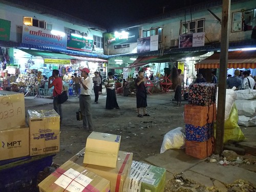
Eastern Long Distance Bus Terminal, Yangon: 21st April 2018.
Somehow, we got our own luggage into the commodious luggage hold but only after 7 men (5 runners, one unloader and one loader) had transferred the contents of a packed covered pick-up to the coach in an attempt to show the limits of the luggage space. The coach was a modern Chinese offering with left hand drive. The left hand drive was quite a relief in a country which now drives on the right (following a pronouncement by the notorious General Ne Win in 1970). Even when the legacy of right-hand drive vehicles for driving on the left had been replaced, the replacements were often from left-driving nations (most notably Japan), to the discomfort of nervous front seat passengers. Each side window of the coach was provided with heavily-swagged curtains giving, I thought, a curious 'Gipsy’ feel.
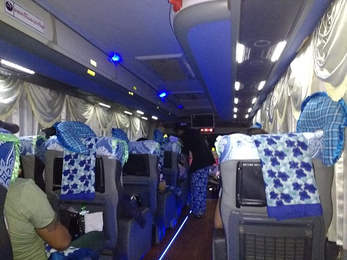
Our coach from Yangon: 21st April 2018.
We started our journey, around 9.15 p.m., travelling backwards. In common with many Myanmar bus stations, arriving buses head towards a long building divided into offices, waiting areas and maintenance bays for the various companies, meaning that departure involves reversing into a continuous flow of buses, taxis, pick-ups, motor cycles, push bikes and the variety of modified light carriers which inhabit these areas. After a series of starts, shouted warnings, urgent horns and fierce stops, the coach inserted itself into the melee and, now travelling forwards, after a few minutes we found ourselves on the main road where speed picked up giving a demonstration of just how hard the suspension was.
By midnight, we’d pulled up at one of the roadside cafes that service the long distance coaches. By western standards, most of the toilets at these places are rather primitive but, at the café areas, the staff perform prodigious tasks of providing fresh-cooked Myanmar food to a rapidly-changing clientele. Fast it may be but it does seem to involve an awful lot of shouting between staff. After a couple more hours on the road we made another refreshment stop where the toilet facilities were quite restricted. I’d assumed we’d leave the coach at Mawlamyine around one hour later, as we had previously, but I discovered we were travelling further on the coach. We didn’t stop long at Mawlamyine Bus Station but we stopped again on the outskirts of town whilst parcels were extracted from our luggage compartments and stuffed into a pickup truck which had appeared. Around 6.30 Saturday morning, the coach stopped again near a road junction in Mawkan, which I recognised as our drop off point the previous year when we headed north from Dawei in a minibus. The manager from Ko-Dut Drop In Centre was again waiting for us with a taxi. There was a slight delay because the parcels unloading on the outskirts of Mawlamyine had managed to thoroughly mix-up the remaining parcels and luggage but, after a frantic few minutes, we’d retrieved everything we’d started out with and were able to board the taxi and drive the last few miles to Ko Dut. When we arrived, there were plenty of staff but the building wasn’t besieged by children so I wasn’t surprised when the Doctor told me the distributions would be held in Ko Dut Monastery, as the previous year.
Although I’d managed some sleep on the journey, tiredness was starting to overtake me but a shower (Burmese style) revived me a little and the Doctor, his wife and I took breakfast together (oatmeal, fried egg, white bread and margarine and English Breakfast tea for me). All the young volunteers then had a ‘second sitting’ of breakfast, by which time the taxi had returned and it was time to load the sacks full of uniforms, towels and snacks for transfer to the monastery. The attractive red and blue traditional Burmese shoulder bags had previously been packed with the stationery being given to each child and the volunteers ferried these to the monastery using their own motor bicycles, the driver and one or two passengers each festooned with as many bags as they could manage.
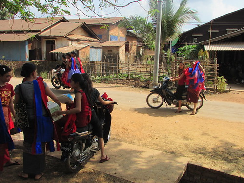
Distribution at Ko Dut Monastery, 2018: Volunteers ferrying school bags by motor cycle from the Drop In Centre to the Monastery.
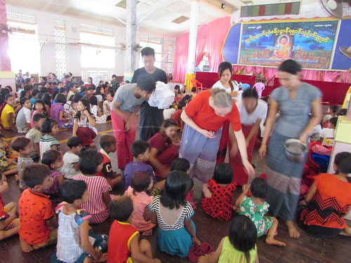
Finally, the taxi returned to take the Doctor, his wife and the writer to the monastery. In the large assembly hall, there were separate groups of, mainly young, children from both Government schools and Mon Ethnic Schools who were to receive the distribution of stationery and a new school uniform.
As more children arrived, the individual groups were combined into two phalanxes, theatre-style but without the cbairs. Eventually, a senior monk from the monastery arrived accompanied by a young monk who, I was to discover, was an excellent English speaker. The monk encouraged the children to recite a clearly well-known prayer and afterwards he addressed them for a few minutes. Afterwards, the young monk translated the gist of the speech: the importance of education, remembering that it makes you clever, not necessarily good and the evils of drugs. Whilst not a Buddhist, I agreed with these sentiments. The monk also made gracious comments about foreign donors who make this type of distribution possible.

Distribution at Ko Dut Monastery, 2018.
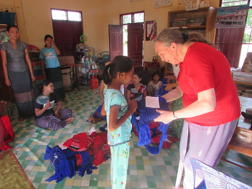
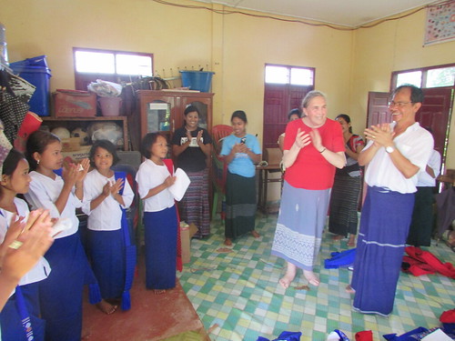
The senior monk asked me to address the children and my brief English homily was translated into the Mon dialect by one of the teachers. The shoulder bags packed with stationery were then presented to each child. There were insufficient white towels to allow each child to have one, so the Doctor instituted a lottery which added to the fun. Square lottery tickets had been cut from white paper and winning tickets were marked with a symbol. Each ticket was then tightly rolled. Another little ceremony presented the winners with their prize.
Distribution at Ko Dut Monastery, 2018: Jan helping to distribute lottery tickets for the limited number of white towels.
All the children then formed up on a large, concrete staircase for the traditional group photograph.
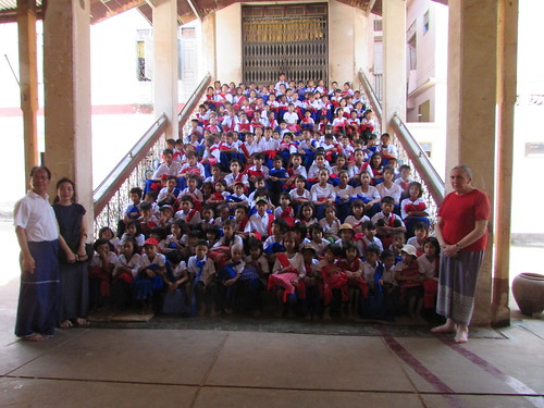
Distribution ar Ko Dut Monastery, 2018: the Group Photograph.
This format was repeated at our second visit of the day to the Drop In Centre at La Mine which is quite small but provides vital support to the youngsters. Most of the children remembered previous visits which I’d made and the teachers and volunteers were unchanged. The element of dependability can be so important in the lives of children lacking traditional family support.
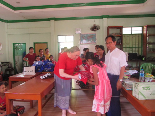
Distribution at La Mine Drop In Centre
The lottery for white towels followed: an Imaginative volunteer had decorated winning tickets with a 'smiley face'.

A winning ticket!
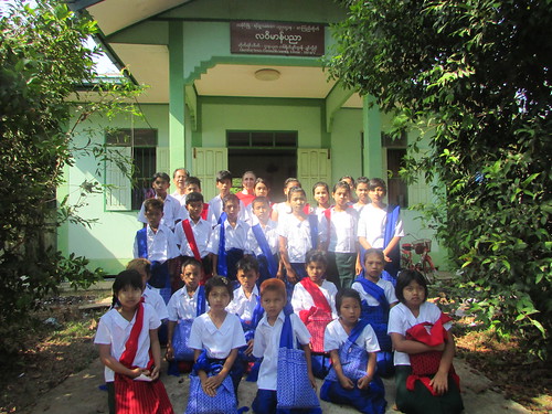
Distribution at La Mine Drop In Centre: the group photograph.
After the group photograph at La Mine, we drove to our final visit of the day, to another small Drop In Centre at Mot Ka Nin. Once again, staff and students were largely unchanged since my last visit about one year ago.
Distribution at Mot Ka Nin
Distribution at Mot Ka Nin, 2018: Smiles all round!
We then retraced our route to La Mine where we took ‘sweet tea’ and dinner in one of the many tea shops near the large monastery.
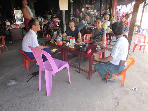
‘Sweet tea’ and dinner in one of the many tea shops near La Mine Monastery.
After our meal, my friends paid their respects to the Buddha Image in the temple. The simple piety of the Myanmar people I find very moving.
In the town, we stopped to purchase fresh Durian fruit. This is never a simple task in Myanmar and invariably there is good-natured haggling before the deal is struck.
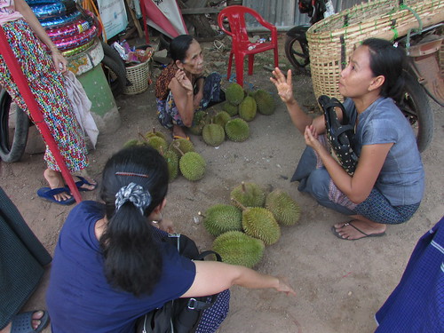
Purchasing Durian Fruit in La Mine
Then, it was back to Ko Dut Drop In Centre for the night. At present, electric power at the Drop In Centre is supplied by one of two elderly portable electric generators. The heat had tired me out and I was asleep before our generator was turned off.
Related posts on this website
This is one of a series of posts describing my 13th visit to Myanmar. The post Travelling again is the first post in the series.
Clicking on the 'Next report' link displays the post describing the next events. In this way, you may read about the trip in sequence.
Next report.
Alternately, clicking on the 'All my Burma-2018 reports' link displays all the posts on this trip in reverse date-of-posting order.
All my Burma-2018 reports.
My pictures
Distribution at Ko Dut Monastery, 2018
Distribution at La Mine Drop In Centre
Distribution at Mot Ka Nin
La Mine and Ko Dut D.I.C.
All my pictures on this trip to Myanmar can be found at Burma 2018.
[Pictures linked 10-May-2018, Pictures inserted 26-May-2018]


