skip to main |
skip to sidebar
Events of Friday, 29th September 2017
I'm starting out on another long-distance trip and, once again, the destination is Myanmar (as Burma is now called). When I travelled to Burma for the first time, back in 2008, I little realised the spell this country, and its remarkable people, would weave, resulting in my returning time after time.
That first visit to Burma was part of a breathless, round-the-world affair described in a series of posts here and I've discussed my curious reaction to Myanmar in the post Myanmar, Serendipity and Jan.
This journey just starting will form my twelfth visit to Burma. Apart from now having a number of firm friends in Burma, I find it a most fascinating country, different in so many ways from my own country. Very slowly, I am finding out a little more about the place although, as I commented in the post Myanmar, Railways and Jan when talking about the limited research I'm attempting about the railway system in Burma, "In Myanmar, there always seem to be more questions than answers".
Although I love exploring different places, the process of travelling to them can become a little tedious. On the afternoon of my departure from home the sky was blue and the sun shone bravely, making it harder to tear myself away when the car arrived to pick me up at 5.30 p.m.
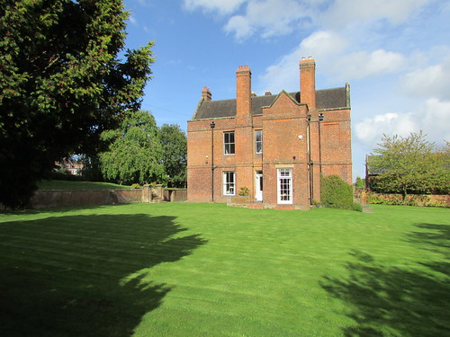
Brewood Hall Garden on 29th September.
So, I find myself writing this in the agreeable 'Emirates' lounge at Birmingham Airport at 8.30 p.m. whilst waiting to board flight EK.038 to Dubai.
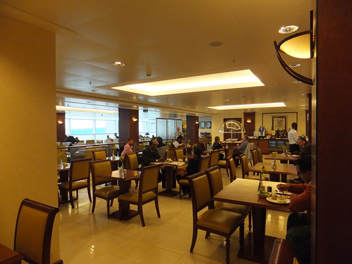
Birmingham Airport: The Emirates Lounge.
This flight is to be operated by an Airbus A380 (Wikipedia has an article here) and Emirates now have 100 of these monsters. I'm afraid I'm not a great fan of the aircraft, despite its impressive technical credentials. My flight onwards from Dubai to Yangon on EK.388 should be handled by a Boeing 777.
Related posts on this website
Next report on this trip.
All my Burma-2017(2) posts.
My photograph albums
Where necessary, clicking on an image above will display an 'uncropped' view or, alternately, pictures from may be selected, viewed or downloaded, in various sizes, from the albums listed:-
Brewood Hall Garden 2017.
Birmingham Airport, England.
In a post here, I talked about the locomotive designer Dugald Drummond and the genesis of his 'T9' 4-4-0, introduced in 1899, for the London and South Western Railway. Brought up in the Midlands in the time of post-war Nationalised railways, the former Southern Railway was very much a 'foreign railway' to me, as were its constituent railways, including the London and South Western Railway. I've written a short post about the London and South Western Railway here and the railway's important London terminus, Waterloo, is described here.
The 'T9' were nicknamed "Greyhounds" for their speed and free running. They had a long life, albeit with various modifications and, when the last of the class was withdrawn in 1963, it became part of the National Collection managed by National Railway Museum.
I'd always admired the class and when I had an invitation, around 1990, to visit Swanage to drive the preserved locomotive (then in LSWR livery and carrying the original number 120), I leapt at the chance. Sadly, when I arrived at Swanage I found out the engine had been 'stopped' for a hot axlebox on the 8-wheel tender. I still got my couple of days driving there but on the Johnson 'Half-Cab' 0-6-0 side tank, which I found a charming locomotive and surprisingly powerful.
Many years later, in 2013, the 'T9' visited the Battlefield Line. This time, it was British Railways lined black 'mixed traffic' livery and sporting the number 30120 which corresponded better with its modified appearance with extended smokebox and stovepipe chimney. Sadly, I wasn't rostered on the 'T9' during its visit but working on the diminuitive Beattie Well Tank alternating departures with the 'T9' was a special experience (described in the post here).
The 'T9' returned to Shackerstone for the 2015 'Santa' trains, alternating departures with 'Austerity' tank 'Cumbria'. Although I was originally rostered on the 'T9' on two of the 'Santa' days, they both were swopped to the 'Austerity' as described here. The 'T9' remained at the Battlefield Line for the start of the 2017 season but when my booked turn on the 'T9' in March was cancelled, I began to think that I was fated never to team-up with Drummond's classic.
However, on Saturday 8th April 2017, I finally got to drive 30120 at the Battlefield Line with Adrian L. acting as fireman and Graham L. cleaner.

Drummond 'T9': 30120 during preparation on 8th April 2017.
I had a second turn on Easter Sunday, 16th April 2017, this time with Jamie W. as fireman. My brief assessment of the locomotive? "Proper Job".

Drummond 'T9': 30120 during preparation on 16th April 2017.
Preparing the 'T9'
When the modernisation of British Railways in the 1950s introduced more complex diesel and electric traction, specific training of drivers and (where provided) secondmen for the different classes of motive power was regarded as essential. But earlier, in the steam era, once footplatemen were 'passed out', they were normally expected to sort out for themselves how to prepare, fire and drive whatever class of engine came along. Originally, I thought this must have been a daunting task but, over the years, I've learned to appreciate the challenge. Despite the variety of designs, the basic principles of steam locomotives have remained remarkably unchanged since the early days and intelligent observation, sometimes coupled with tips from other crews, can solve most queries. So, I enjoyed clambering over the 'T9' and finding out how Drummond had produced his 'masterpiece'.
During his time on Scottish railways, Drummond had learnt the value of rugged, reliable construction and the 'T9' fully embodied these principles. I was impressed by the 1-inch thick steel frames, the robust castings and forgings, the generous bearing areas and the overall simplicity of construction.
The Motion Plate supports the rear of the slide bars and must provide a rigid anchorage, as shown in the picture below. Stephenson Link motion was employed (the increasing popularity of Walschaert's motion in England came rather later). However, well-designed Link motion serves most needs and Drummond's arrangement was considered very successful. The picture below also shows the curved Expansion links which allow alteration of cut-off and direction of travel, in the case of the 'T9' under the control of steam reversing gear.
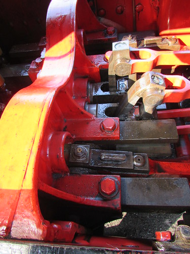
Drummond 'T9': View between frames from left side, showing rear of Motion Plate and Expansion Links.

Drummond 'T9': View between the frames, looking rearwards. L-R: Hornguide for right driving wheel, Right crank (on back dead centre), Four eccentric rods and eccentric sheaves, Left crank (on bottom quarter), Hornguide for left driving wheel.
I was impressed by the compact design of the two-cylinder steam reversing gear, with the cylinders mounted vertically in-line inside the left main frame, just ahead of the left driving axlebox.
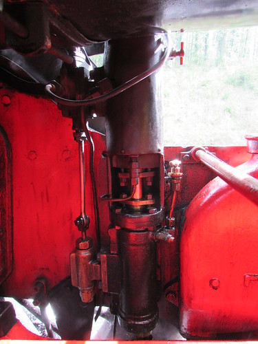
Drummond 'T9': Steam Reverser, mounted inside left main frame.
30120 has the earlier-pattern 'narrow' cab which could be described as 'cosy'. The splashers of the trailing coupled wheels protrude into the cab on both sides and these are extended rearwards to form small toolboxes with a wooden seat on top.

Drummond 'T9': 30120 has the earlier-pattern 'narrow' cab.
The Driver's duties
On most early steam locomotives, the driver's position was on the right of the footplate. Industrial locomotives were usually (but not invariably) right-hand drive. The Great Western Railway stayed with right-hand drive to the end (and beyond - prior to Nationalisation in 1948, the Great Western Railway placed an order with private contractors for 200 of the '94XX' class 'Pannier' tank, leaving British Railways to pick up the bill, as I mention in the article here).
But, on double-track railways in Britain, we drive 'on the left' and, as a consequence, the most convenient position for signals is further to the left. Generally, the driver will have a better view of signals on the left of the track if he is on the left of the footplate. Over time, modern locomotives in Britain became left-hand drive. Some had originally been right-hand drive and were rebuilt as left-hand drive. The iconic 'Flying Scotsman', proudly exhibited at the British Empire Exhibition in 1924, was built as right hand drive, as you can see from the drawing in the article 'Flying Scotsman'. 'Flying Scotsman' had been rebuilt with left-hand drive many years before I first got my hands on her at Birmingham Railway Museum in 1992 (described here).
The 'T9' is left-hand drive so the main driving controls are on the left of the cab - Reverser, Regulator and Vacuum Brake.
Reverser
Steam-operated power reversing gear is fitted, controlled by a short lever painted red which stands vertical except when changes to setting are required.
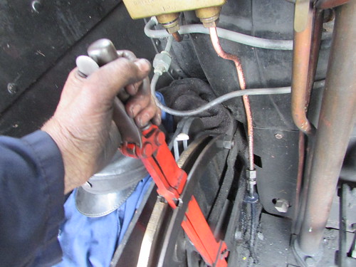
Cab Reversing Lever being placed in 'neutral', having just 'Linked-Up' the gear in 'Forward' to the position indicated by the white-painted pointer which moves over the engraved, brass cut-off indicator scale.
I'm afraid I found a tendency for the gear to 'creep' towards full gear when travelling forwards but reverse gear was better-behaved.
Regulator
The regulator is closed in the 'seven o'clock' position. It is progressively opened 'underarm' as the lever is pushed towards 'four o'clock' (the only other engine I can remember driving with an 'underarm' regulator was the 'B12', which was right hand drive - this is mentioned in the post Locomotive Regulators (part 2)).
Vacuum Brake
A combined fitting provides small ejector, large ejector, driver's brake application valve, vacuum relief valve and release valve together with a horizontally mounted handwheel on the shut-off cock. Vacuum brake cylinders are provided on both locomotive and tender. The tender brakes can also be applied from a handwheel.
Blower Valve
The Blower Valve Handwheel is tucked in the front left corner of the cab, only accessible to the driver. More modern practice favours a position accessible to both driver and fireman. The actual blower valve is located adjacent to the smokebox, operated by a rod passing through the left handrail.
The Fireman's duties
As commented above, early steam locomotives tended to be right-hand drive, meaning the fireman normally worked from the left side of the footplate, favouring right-handed firing. But on the 'T9' and many other designs (later LMS, LNER, SR and BR locomotives) the fireman is on the right, favouring left handed firing. Some fireman were happy either way round, others permanently grumbled if forced to fire the 'wrong' way. Drivers could get bad-tempered if they felt that their fireman was 'invading their space' and there are many tales of drivers drawing a chalk line down the middle of the footplate - I recount one of these in the post A Day on the Footplate (2).
There's a (still incomplete) introduction to firing steam locomotives at MIC - Firing Steam Locomotives (1).
The position of the coal supply in the bunker or tender also varies between designs, sometimes being delivered at footplate level, requiring the fireman to bend, sometimes appearing at a raised shovelling plate (often called the "married men's tender").

Drummond 'T9': Watercart tender, showing raised shovelling plate, tender handbrake and large toolbox.
The coal then has to be fed through the firehole which, according to locomotive class, varies in shape, size and height above the footplate and can be equipped with different patterns of firedoor requiring some adaptability on the part of the fireman. The 'T9'has a top-hung, inward-hinging cast firedoor which can be held open at various angles by the use of a ratchet, controlling the amount of 'secondary' or 'top' air admitted to the firebox. The top-hinging means that a separate Baffle Plate is not required - when open, the door acts its own baffle. This design was quite widely used in this country (certainly by the L.N.W.R and Lancashire and Yorkshire Railway) and also overseas. The cast door can be a little heavy to work frequently but a hinging half-flap is provided which, when raised, may allow the firedoor to remain open.
Great Western firemen became adept at winding the chain from a similar flap-plate around the operating handle of the main, sliding firedoors. A 'pull' on the chain would then 'flip' the flap-plate open or shut with very little effort, leaving the main firedoors open. If the steaming rate demanded was not too high, they would leave the flap-plate shut and fire 'over the top', which required accurate shovel-work.
Stanier engines for the L.M.S. had a similar flap-plate, allowing a similar technique to be adopted.
The Great Northern Railway (later the L.N.E.R.) used a 'Trap-Door' design of firedoor, very convenient in use, once the technique was mastered. There's an introduction to this firedoor in the article Firing a 'B1'.
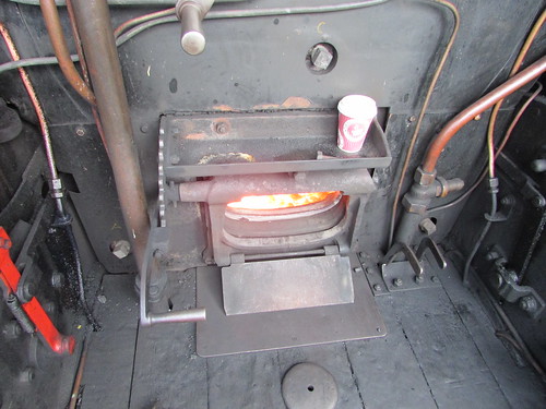
Drummond 'T9': Firehole with top-hung, inward-hinging firedoor. Note Flap Plate.
Different designs of firebox then require different firing techniques to produce steam economically. The 'T9' has a reasonably long 'box', almost 7 feet long front to back inside (nowhere near the length of, say, a Great Western 'King') with a sloping grate. If the fireman is lucky, when 'on the road', he can feed coal to the back the firebox (nearest the footplate) and the motion of the engine will trickle it forward to the front.
The 'T9' Tender
The preserved 'T9' has the distinctive 8-wheel 'Watercart' tender, giving a coal capacity of 5 tons and a water capacity of 4,000 gallons. Unusually, the two 4-wheel bogies are provided with inside axleboxes. Although tenders carried on eight wheels are very common overseas, I can only recall designs with outside axleboxes. A locomotive depends upon its supply of water as discussed in the post Water, water, everywhere. This was particularly important for the L.S.W.R. (later Southern) lines as they stretched far west into the territory of the Great Western Railway but, alone amongst major British railways, no water troughs were ever installed. On the West of England services, changing engines was frequently undertaken at Salisbury and, of course, water was available at major stations and yards.

Drummond 'T9': The 8-wheel 'Watercart' tender is provided with inside axleboxes.
Passage of Water from Tender to Boiler
Water from the tender is fed by gravity via two water cocks set in the wooden floor of the cab to two live steam injectors, one on either side of the firebox.
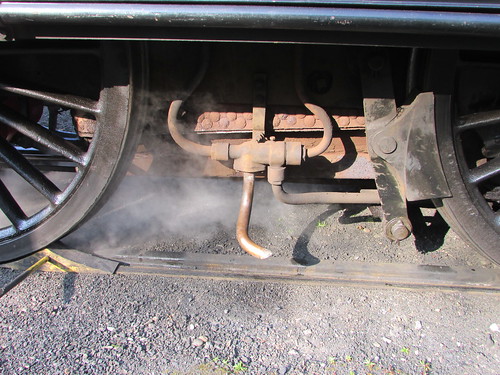
Drummond 'T9': Driver's side Live Steam Injector, suspended on a simple bracket alongside the firebox. The connections are (L-R): Delivery to boiler, Overflow, Cold water, Steam.
The injector uses steam from the boiler to pressurise the water to greater than boiler pressure (a feat of apparent magic possible due to the work of mathematician Bernoulli and engineer Henri de Giffard), allowing the water to feed the boiler through a one-way valve called a Clack Valve (there's a little more about the Clack Valve in a post here). In this way, water boiled into steam and converted into motion in the cylinders could be replenished. The steam for the injectors is taken from the top of the firebox and controlled from the cab by the Injector Steam Valves.
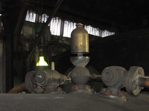
Drummond 'T9': View showing top of firebox with whistle and, left and right, Injector Steam Valves controlled by long rods extending to handwheels in the cab.
The pressurised water from the injectors is fed into the boiler via clack valves on the horizontal centre line of the front ring of the boiler shell on both sides. This was the 'classic' position for introducing feed water into locomotive boilers until the advantages of 'top feed' were understood in the 20th century.
 Drummond 'T9': 30120 being prepared at Shackerstone, showing the position of the Driver's Side Clack on the 'front ring' of the boiler shell.
Related posts on other sites
Brief data on 30120 and 'T9' (Rail UK Site).
Related posts on this site
Dugald Drummond and the 'T9' - Historical Background.
My Pictures
Where necessary, clicking on an image above will display an 'uncropped' view or, alternately, pictures may be selected, viewed or downloaded, in various sizes, from the album listed:-
Drummond 'T9'.
On Sunday 20th August 2017, I was driver at the Battlefield Line, once again on 'Cumbria', an 'Austerity' tank locomotive. You might imagine that regularly driving on the same line would lead to boredom, but no two days are the same and this one certainly didn't turn out as planned.
There was a 'Gold' footplate experience course booked so I signed on at 06:30. Our lady fireman, Tracey, was 'booked fireman' but on that day she was observing our trainee, Ritchie, with a view to his becoming a 'Passed Cleaner' which would enable him to act as a fireman in his own right in the future. When I arrived Tracey and Ritchie had already done the initial checks and lit-up, so I set-to oiling and examining the locomotive.
An intimation of the problem to come was quickly revealed as I found the left leading spring with a broken 'leaf' near the buckle and the rear portion of the leaf was working its way out of the buckle.
In steam locomotive design, the weight of the engine is transferred to the wheels via springs connected to axleboxes arranged to slide up and down in hornguides attached to the main frames. Some vertical movement of the axlebox is possible as the spring deflects from its 'rest' position', but the tension in the spring then acts as a restoring force to return the axlebox to its 'rest' position. Each 'wheelset' (an axle with two wheels) has two axleboxes embracing two machined areas on the axle (the journals) so that each wheel has 'independent suspension' allowing it to rise and fall, following 'bumps' in the track.
Various types of spring are used but the laminated leaf spring, as used on the 'Austerity' tank, is most common. Two arrangements are possible with laminated springs, depending upon whether the spring is mounted above or below the associated axlebox. The 'Austerity' tank is 'undersprung' where each end of the spring is connected, via links which allow the spring to 'flex', to the main frames and the buckle in the middle of the spring is connected to the bottom of the axlebox.

'Austerity' Elevation showing 'undersprung' laminated springs on each axle (Industrial Railway Record).
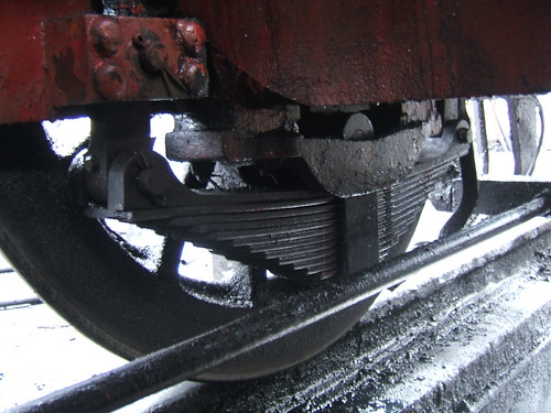
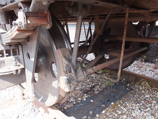
This picture shows the (undamaged) spring on the left leading axlebox of 'Austerity' tank 'Royal Pioneer'. The long, round horizontal rod across the foreground is part of the brake rigging.
There were no maintenance staff on duty at Shackerstone and, even if there had been, jacking-up the engine and changing a main spring would have made us very late into traffic, jeopardising both the footplate experience course and the advertised service. Resident Peckett locomotive 'Sir Gomer' was standing next in line in the shed but completely cold. I didn't even consider using 'Sir Gomer' because, even if fit for traffic, the time to bring the cold locomotive into steam would have meant no trains until the afternoon.
In the days of steam on post-war railways various techniques were adopted in emergency to reduce the time it took to make an engine steam but the more 'agressive' techniques tended to reduce boiler life and increase maintenance costs. The coefficient of expansion of metals means that when a boiler is brought to working temperature, the dimensions increase. If this is done too quickly, the stresses on rivets, stays and boiler tubes may result in leaks. I think I worked out that the boiler on a Great Western 'Castle', for example, becomes about half an inch longer when hot (and the design allows the firebox to slide on supports to accommodate this expansion). Some sheds kept a flexible hose attached to a long hooked pipe. The hooked pipe was lowered into the chimney of the engine to be steamed and the hose was attached to another engine already in steam. Allowing steam to flow through the pipe and escape from the chimney provided a draught to 'encourage' steaming in the way that the Blower stimulates the fire on an engine already in steam. Another approach was to couple the engine to be steamed to a second locomotive and drag it up and down the yard with the reverser of the engine to be steamed set in the 'wrong' direction. The cylinders acted as air pumps, pressurising the boiler with compressed air. When the Blower Valve was opened, the escaping compressed air provided a draught to the fire (at least briefly).
As an alternative, I found a large sledge hammer and, as carefully as I could, hammered the protruding section of the broken spring leaf back towards its original position. In the limited time available, that was as much as I could do and I decided that I would take the locomotive into traffic and keep my eye on it during the day.
Our driver on the 'Gold Experience' course arrived early and we set off light engine for Shenton, with me explaining the use of the driving controls and the need to comply with the various speed restrictions along the line. We returned to Shackerstone and coupled onto the waiting train. By this time, our 'Gold' driver's family had arrived and they boarded the train as I introduced the complications of the vacuum brake which we'd be using on this trip. We made and uneventful trip to Shenton, uncoupled and 'ran round' then returned to Shackerstone. Our 'Gold' driver had performed well and had clearly had a most enjoyable time. We all said 'good bye', uncoupled, ran round, watered and prepared to take the 11.15 a.m. train which departed a few minutes late.

'Cumbria' ready to leave Shackerstone on an earlier date.
We completed three of the five 'booked' round trips but, by this time, the broken spring leaf had worked its way back out a few inches and my attempts to persuade it to return nearer to its correct position were not successful. Not wanting to risk a complete failure down the line (with the risk of 'stranding' passengers) I decided to 'fail' the locomotive. We believed the Diesel Multiple Unit (DMU) was serviceable so it was agreed that Ritchie would go and start-up the DMU whilst Tracey and I limped onto shed and disposed of the steam locomotive.
I need to introduce a little background here. I have described my previous turn on the DMU on Wednesday 2nd August 2017 in the post Summer at Shackerstone when we were using the 2-car set (51131/51321). After that turn, Ritchie took 51321 out of service for repairs to the roof so subsequent services had operated with 51131 coupled to the single-unit 'Bubble Car' 55005. The versatility of the Electro-Pneumatic control systems allows this sort of unconventional arrangement. However, I learnt that, subsequently, one of the two engines on 55005 had failed and there had been some difficulty in isolating the failed engine.
Like many cars, a Diesel Multiple unit requires a gearbox to match the limited range of engine speed over which an internal combustion engine can provide reasonable torque with the wide range of vehicle speed required. Many of the British Railways designs (and all the examples at Shackerstone) use an Electro-Pneumatically controlled (E.P.) epicyclic gearbox. Unlike cars, a Diesel Multiple unit travels as far travelling backwards as forwards and needs a range of gears in both directions. So, instead of making 'reverse' an 'add-on' to a gearbox, it is made a separate function, called the Final Drive, mounted on the driven axle and also E.P. controlled. The engine always rotates in the same direction and the drive, having passed through the gearbox, turns a Cardan Shaft, again always the same direction. The reversal occurs within the Final Drive unit by operating a selection 'Dog' splined into the input shaft from the gearbox but free to slide so as to engage one of two bevel gears which, via a spur gear, determine the direction in which the axle revolves. The sliding 'Dog' is actuated by a Selector Fork controlled by two E.P. valves.
To take an engine out of service the Starter Motor is electrically isolated by operating an underframe-mounted switch adjacent to the engine.
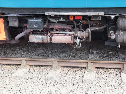
55005 Number 2 Engine: The Engine Isolator Switch is the orange-painted square box underneath the wooden footstep.
A failed engine must also be mechanically isolated from the wheels by latching the 'Dog' Selector Fork in a central, 'neutral' position. This is achieved by pulling-out and turning an Isolating Plunger mounted on top of the final drive. A spring then pushes the Isolating Plunger so as to engage in a groove when the Selector Fork and 'Dog' are in the 'neutral' position, confirmed by rotating the Cardan Shaft by hand. The Isolating Plunger is in an inaccessible position almost on the centre line of the vehicle so the Guard's Compartment is equipped with a special long-handled fork (always called the 'Toasting Fork') to assist.
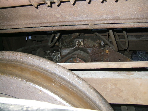 DMU Final Drive: The small rectangular casting near the centre of the picture is the Isolating Plunger. Pulling and turning the bar into the horizontal position isolates the drive.
My post Diesel Multiple Units has links to training material produced by British Railways: black and white sound films and training notes.
Ritchie completed the fourth round trip with the 2-coach train running on three engines. With an engine 'out', performance is affected but Ritchie found the operation unexpectedly sluggish. By the time he returned to Shackerstone, Tracey and I had completed disposal of the steam locomotive so Ritchie invited me to drive the last train. However, as soon as I started away, I agreed with Ritchie that the unit seemed very 'unhappy'. Having gone barely 300 yards, Ritchie decided that we should cancel the run. We never like to disappoint passengers but, with the risk of failing 'in the section', I readily agreed, 'changed ends' and slowly drove back to the platform to disembark our passengers. Having 'changed ends' again, I then very slowly drove to the DMU siding and Ritchie (who, of course, owns the diesel multiple units at Shackerstone) immediately set-to dismantling the Final Drive and, before long, discovered that the 'Dog' (described above) had shattered, suggesting that permanent isolation might not have been achieved. He removed the broken pieces and decided to remove the Cardan shaft so that the midweek railcar service could continue whilst he arranged the necessary repairs.
What happened next?
I was rostered as driver on 'Cumbria' a week later, Sunday 27th August 2017) and, again, there was a 'Gold' footplate experience course followed by five passenger trips to Shenton and back. Temporary repairs had been made to the spring (tack welding and clamping) and no problems were encountered. I was delighted to be 'paired' with Ritchie, now a Passed Cleaner on his 'maiden' solo firing turn. We both had a very enjoyable day.
I was re-united with the DMU for a 'Midweeek' turn on Wednesday 13th September 2017 with Grant as Guard. The initial problem we faced was that the 2-coach DMU (51131 with both engine serviceable coupled to 55005 with one engine in use) had been 'boxed-in' by a class '04' shunter and a freight wagon. There was no passed '04' driver on site but I was happy to use the DMU to push the vehicles down the 'North End', out of our way. I brought the DMU onto the wagon and coupled on, using the wagon's 'Instanter' coupling in the long position (there's more about the 'Instanter' here). But then we had to release the brakes on the '04'. Brakes on diesel shunters are normally 'co-acting' - they can either be applied by a proportional brake valve when an air receiver is 'charged' (from an engine-driven compressor) or, alternately, manually, (usually from a handbrake wheel in the cab). Neither Grant nor I could budge the handbrake wheel on the '04'. It was clear that the brake had been applied using air and the handbrake wheel then turned to 'take up the slack', resulting in a brake application very difficult to release by hand. It took Grant and I some minutes (using a fishplate as a lever) to release the brake in small steps. Then, with Grant keeping a lookout from the cab of the '04', I propelled the unwanted vehicles out of the way. We re-applied the '04' brake (by hand!), I uncoupled and shunted back to the station with waiting passengers curious about our antics. I think we were seven minutes late with the first departure but, even with one engine out of use, had no difficulty keeping to time for the rest of the day. Grant and I agreed that we'd had a very pleasant day.
Related posts on this website
The 'Austerity' 0-6-0ST locomotive.
To see all my posts about Diesel Multiple Units, select Label 'DMU' or click here.
To see all my posts about the Battlefield Line, select Label 'Battlefield Line' or click here.
My photograph albums
Where necessary, clicking on an image above will display an 'uncropped' view or, alternately, pictures from may be selected, viewed or downloaded, in various sizes, from the albums listed:-
'Cumbria'.
Royal Pioneer (Up close & personal) [Pictures of another 'Austerity' tank].
All my Battlefield Line albums.
The Mutual Improvement Classes of the old steam railways still continue for today's preservation volunteers. This is one of a series of posts taken from notes of talks given by Jan. To find them all, select label 'MIC' or click here. There's a periodically-updated list of these posts here.
The following notes for shunters are aimed at persons working on preserved standard gauge railways in the United Kingdom. The Shunter (where I mean the person on the ground involved in marshalling a train and coupling and uncoupling vehicles - not the locomotive engaged in the marshalling), is engaged one of the more dangerous tasks carried out on a railway. This role may be carried out by dedicated shunters, by Guards or Footplate crew. Anybody carrying out this work must be suitably trained and assessed as competent and be using the specified Personal Protective Equipment (PPE).
The shunter must not go between two vehicles unless they are both stationary and there is a 'Clear Understanding' with the driver of any locomotive. Muttering "Going between" and disappearing between vehicles is not adequate - there must be an explicit acknowledgment from the driver that it is safe to go between vehicles.
Please remember "Jan's Three Rules" for working on a railway:-
1. Do it Safely.
2. Do it Safely.
3. (Can you guess?) Do it Safely.
Just moving around in a railway yard presents a challenge. The ground is rarely level and can rapidly change texture (ballast, wood, earth, paving, tarmac). There are numerous obstructions to catch out the unwary. In addition to various posts, fences and misplaced debris, there may be hand levers to operate points. If there's a signal box or ground frame in the vicinity, in addition to various types of signal there is likely to be point rodding, cranks/compensators, signal wires and signal pulleys.
This introductory part deals with the two simplest types of coupling used on freight wagons mentioning the hand brakes typically provided. In the steam era, the 3-link and 'Instanter' couplings were the most common types used on freight trains. Individual vehicles usually had hand-operated brakes, used as both a 'parking' brake and, partially applied, as a means of retarding the vehicle when descending an incline. On the move, the locomotive brake and the handbrake applied by the guard in the Brake Van at the rear of the train were the only means of controlling the train. It became mandatory on trains carrying passengers to have an 'automatic' brake operable throughout the train. Gradually increasing numbers of freight trains were fitted with 'automatic' brakes on all or at least a group of vehicles next to the engine (called a 'fitted head'), allowing higher running speeds.
The 3-link Coupling
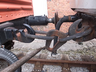
The simplest coupling in use on standard-gauge railway vehicles in the United Kingdom comprises a strong Drawhook from which are suspended three links. Whilst easy and quick to attach or detach this type of coupling to an adjacent vehicle, there will always be 'slack' between the vehicles, and the driver must be aware of this. Because both adjacent vehicles have the same design drawhook and similar coupling links, the shunter can normally choose whether to put the left coupling links on the right drawhook or the right coupling links on the left drawhook. Should a link fail on a journey, it was possible to complete that journey by using the 'good' coupling links. However, most freight guards would keep a 'spare' 3-link coupling to hand so that a failed coupling could be replaced. Particularly in freight yards, spare 3-link couplings were often to be found lying around.
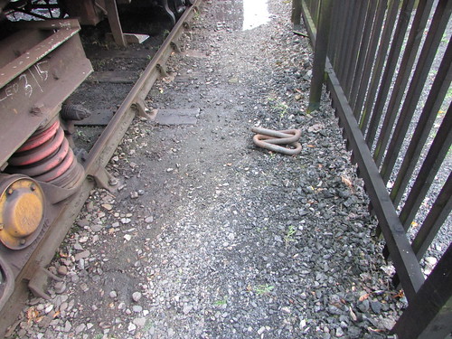
A spare 3-link coupling was often to be found lying around.
The hole in the drawhook which accepts the associated link is accessed via a 'keyway' narrower than the diameter of the steel bar from which the links are made. The prevents a coupling from becoming accidentally detached from its parent drawhook but, without special provision, this would prevent a failed coupling from being easily replaced. The 'special provision' is called the 'Kedge' - a flattening part way along a long side of the end link. This flattening makes the kedge thin enough to pass through the keyway in the drawhook, allowing the coupling to be suspended from the parent drawhook.

3-link coupling, showing the 'kedge' in the long side of the end link which allows the coupling to be suspended from the parent drawhook.
The slack in the couplings on this type of train (referred to as 'loose-coupled') can be used to advantage by a driver in starting a heavy train. If the locomotive has eased back on the train, only part of the train weight has to be moved initially with additional load taken by the locomotive as couplings tighten towards the rear of the train. However, on an undulating route, additional skill is needed as the wagons 'bunch up' on down grades and 'pull out' on rising grades. Co-operation with the Guard, in operating the handbrake in the Guard's Van, can minimise the effects.

3-link or 'Instanter' Coupling: End view (from a Railtrack document).
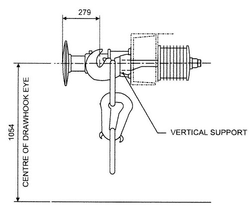
Instanter Coupling: Side view. The 3-link coupling is similar, but with a plain, oval centre link (from a Railtrack document).
The 'Instanter' Coupling
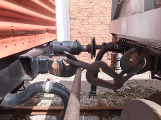
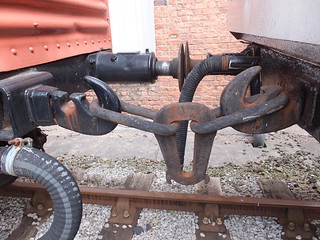
The 'Instanter' is similar to the 3-link, except that the middle link has a complex shape with two 'ears' allowing it to be placed in either of two positions, corresponding to 'long' or 'short'. In the 'long' position, the coupling has the ease-of-use of the 3-link. In the 'short' position, some of the 'slack' is taken out of the coupling and the motion of the train may be better (particularly for the Guard at the end of the train!).
Diagram of 'Instanter' Couplings in the 'Long' and 'Short' positions (From the L.M.S. General Appendix to the Working Time Tables 1937).
The Shunting Pole
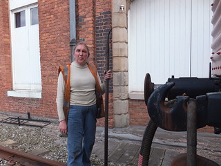
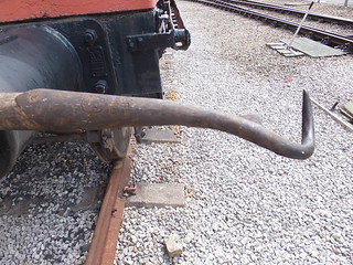
The Shunting Pole was an invaluable aid to Shunters. A stout, round, wooden staff, usually made from ash was provided with a specially-shaped metal end, curled like the tail of a pig. Armed with this tool, a skilled operator could rapidly couple or uncouple both 3-link and 'Instanter' couplings. 'Instanter' couplings could also be turned from long to short or short to long positions. This was done with the shunter standing alongside the wagons so it was both safer and faster. Some strength and some practice is required to become proficient. It's also important to check the pole regularly for damage. In former times, employees were sometimes tempted to make use of shunting poles in unauthorised ways. The frequent need to apply or release wagon handbrakes could tempt the shunter to use the shunting pole as a lever (rather than the properly-designed brake stick) or, worse, to avoid chasing a wagon down a siding shunters might wedge the shunting pole into the underframe of a moving wagon and ride on the protruding pole. Serious injury or death could follow so no modern volunteer should copy these risky practices.
Jan at the Museum of Science and Industry, Manchester (with Shunting Pole and looking rather fierce).
The shunting pole, showing the 'business end'.
Coupling either a 3-link or 'Instanter' coupling to the drawhook of the adjacent wagon using the shunting pole. The shunting pole is held under the buffers, engaged with the bottom link and swung up and across. The shunting pole is released by twisting.
Using the shunting pole to uncouple a 'long' 'Instanter' or 3-link coupling from the drawhook of the adjacent wagon. The metal part of the Shunting Pole is placed under the link and the pole swung upwards. This is sometimes done with the pole over the buffer shank.
'Instanter' Coupling after turning to 'short' position. The centre link is turned, by engaging the pig's tail with one of the 'ears' on the centre link and pulling upwards.
'Instanter' coupling: Using the shunting pole to place an 'Instanter' coupling in the 'long' position. Beforehand, there must be sufficient slack in the coupling to allow the centre link to be turned, by engaging the pig's tail with one of the 'ears' on the centre link and pulling upwards.
Wagon Brakes
Freight wagons are provided with hand-operated brakes, usually capable of being applied from either side using a long, pivoted brake lever but short levers or handwheels are also used. Even with a long brake lever, significant downward force may be needed to apply the brake effectively. The Brake Stick (described below) can assist in safely applying and releasing handbrakes. There's a little more about brakes on railway vehicles here and pictures of a range of preserved wagons in the album Freight Rolling Stock.
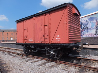
A typical 4-wheel Van (or Covered Wagon) provided with a handbrake lever on both sides. Operating either lever downwards applies the brakes but both levers must be raised to release the brakes.
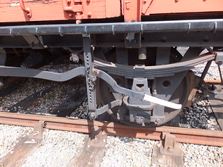
Detail of handbrake lever, showing the pin and chain used to 'pin down' the brakes when parked or descending an incline.
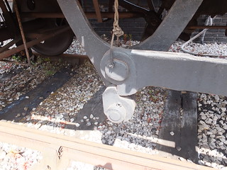
Detail of tranverse brake shaft, showing how the handbrake lever on either side applies a strong force to a cam to turn the transverse shaft and apply the brakes.
Detail of brake rigging, showing cast iron brake blocks.
The Brake Stick
The Brake Stick is wooden, about 3 feet long. Half the length is rectangular, around 2.5 inches by 2 inches in section. The remainder is rounded and tapered to about 1.25 inches diameter at the end. The rectangular section is placed over the Brake Lever and wedged under the underframe or the spring. Pressing down on the rounded section provides additional leverage and the pin is inserted in a pair of holes to retain the brake force. The brake stick may be needed to safely remove the pin when it is necessary to release the brake. As with the Shunting Pole, it's important to check the Brake Stick regularly for damage.
More on this topic at The Role of the Shunter (2).
Related posts on this website
MIC - Brakes.
Related photograph albums
Pictures from may be selected, viewed or downloaded, in various sizes, from the album listed:-
Freight Rolling Stock.
On Saturday 12th August 2017, I was back at the Battlefield Line, this time on 'Cumbria' which had recently had a washout and repairs to the fireman's side injector.
There was no footplate experience course booked so it was a leisurely start for me signing on at 08:30, although Adrian L. (who was acting as fireman in the morning) had arrived a couple of hours earlier to get the engine lit-up. In addition to the normal service of five return trips between Shackerstone and Shenton, in the evening there was a 'Fish and Chip Special' which I'd also agreed to 'cover'.
I 'oiled round' and examined 'Cumbria' and we were 'off shed' in plenty of time to attach to our 4-coach train waiting in platform 2 at Shackerstone. After the first two round trips to Shenton, Adrian was replaced as fireman by Steve A. But Adrian had not finished - on the contrary, donning his 'catering' hat, he and Gina spent the afternoon sorting out supplies for the evening 'Fish and Chip Special' whist Steve and I completed the normal 'diagram' with another three journeys to Shenton and back.
Arriving back at Shackerstone after our fifth trip, we were routed into platform 1 where the main station facilities (tea room, museum and toilets) are located. I deliberated 'stopped short', leaving room at the north end of the platform for our train to be 're-inforced' with an additional coach for the fully-booked evening special. Steve uncoupled 'Cumbria' and we went to the north end sidings to 'coal-up'. The bucket loading shovel (driven by Adrian wearing another 'hat') soon topped-up our bunker. We then shunted south through platform 2 to replenish the saddle tank from the water crane at the at the south end of platform 2. In defiance of normal conventions, turning the wheel which controls the water valve clockwise opens the valve, rather than closing it. Many years ago, as a reminder, somebody wrote on the wheel in white paint 'Open' and 'Closed' with arrows but this is now faded. If I'm on the wheel, I always have to do a 'double-take' when I hear the cry "That'll do" from my mate on top of the tank to avoid both of us getting a soaking.

Water Crane at Shackerstone. The wheel which controls the water valve is on the right.
Coaled and watered, we coupled onto the south end of the four coaches we'd left in platform 1 and I was able to watch the shunting being performed. The maroon-painted coach to be added to our train was behind the self-powered Tamping Machine in siding 2 at the north end so Adrian (now with driver's 'hat') 'fired-up' the tamper and moved into platform 2, pulling the extra coach. The Class 04 diesel shunter moved onto the north end of our train and attached the nearest coach (a 'Mark 1' in Western Region 'chocolate and cream' livery), first drawing it back to the north end, then propelling it onto the maroon-coach behind the tamper in platform 2. The '04' then pulled both coaches back to the north end, before finally propelling them towards the coaches waiting in platform 1.

Adrian leaning out from the '04', checking for handsignals from the shunter, as he propels two coaches onto the three already in platform 1.
British passenger coaches built after the 1948 Nationalisation of railways were fitted with 'Buckeye' couplings, retaining a conventional drawhook which is used to attach the locomotive using a screw coupling (only one British steam class was originally fitted with 'Buckeye' couplings - Gresley's 'A4'). On coaches, the 'Buckeye' is hinged and has to be lifted to the horizontal position to allow coupling to a similarly-fitted vehicle. The substantial hook has a hinging 'knuckle'. To couple, two vehicles are brought together with one of the knuckles in the 'open' position and the adjustable buffers set to the 'Short' position.
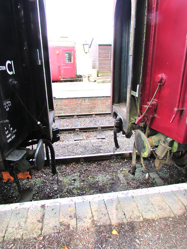
BR Coaches being shunted together. Buffers in 'Short' position for use with Buckeye coupling. Note 'saddle' stowed on bracket adjacent to buffer.
As the two couplings contact, the open knuckle is forced closed and a mechanical latch drops, locking the knuckle closed. In addition to the shunter confirming visually that 'the pin' has dropped, a 'pull test' is conducted where the locomotive tries to separate the vehicles. Unfortunately, to connect the brake hoses and, when required, the steam heating hoses, the shunter still has to clamber underneath the vehicles. The electrical jumpers to allow the guard to control the carriage lighting also require connection.
To uncouple, pulling a chain on either coupling unlatches that knuckle, allowing the vehicles to be drawn apart. The shunter controls the coupling and uncoupling by hand signals given to the driver of the locomotive performing the shunt from a position alongside the vehicles.
It was a warm summer evening and, by this time, a good-natured crowd of expectant diners had assembled on the platform, waiting to be seated on the train. Steve and I readied 'Cumbria' for a leisurely trip down the line.

'Cumbria' ready to depart with the evening train.
A little late, we received the 'Right Away' from the Guard, collected the Single Line Staff from the Signalman at Shackerstone and trundled down the line. We were not expecting to stop at Market Bosworth but, as we approached the platform, one of our Volunteers was on the platform so we decided to make a stop. He didn't board the train, but had apparently ordered a portion of fish and chips which was safely delivered to him, after which the Guard gave the 'Tip' and we set off again.
I'd been told to stop on Shenton Bank, just before our last station, where there are views across the Leicestershire countryside on both sides of the train. It was a perfect summer evening as the sun sank lower in the sky and the engine simmered quietly whilst our diners enjoyed their food. I felt much happier than the picture below perhaps suggests.
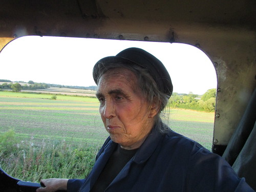
Battlefield Line Fish and Chip Evening Special: We paused on Shenton Bank with views across the Leicestershire countryside.
Food had also been ordered for the loco crew, so Steve 'dropped down' and walked back to collect our fish and chips which we enjoyed whilst waiting. After about fifteen minutes, the Guard gave us the 'Right Away' and we continued to Shenton station. There was then a bout of activity as we uncoupled, ran round and coupled onto the train for the journey back to Shackerstone. Many of our passengers were on the platform, enjoying the warm evening and taking numerous photographs. Once everyone was back on board, we set off on a fairly gentle trip back to Shackerstone.
We arrived back in platform 1, stopping so that all the passenger coaches were in the platform. With 'five on' that meant that the rear of the train didn't leave sufficient clearance for us to use the ground frame giving access to the loco shed. So we ran round, attached to our train and, with the Guard giving hand signals from the north end, propelled the train northwards a short distance to give sufficient room for us to get 'onto shed'. By this time, it was fairly dark. It only remained to put the locomotive in the shed and carry out the normal disposal routine after what had been a very enjoyable day.
Related posts on this website
To see all my posts about the Battlefield Line, select Label 'Battlefield Line' or click here.
My photograph albums
Where necessary, clicking on an image above will display an 'uncropped' view or, alternately, pictures from may be selected, viewed or downloaded, in various sizes, from the albums listed:-
Battlefield Line Fish and Chip Evening Special.
'Cumbria'.
All my Battlefield Line albums.
The Mutual Improvement Classes of the old steam railways still continue for today's preservation volunteers. This is one of a series of posts based on notes of talks given by Jan or with technical content which may be of use to today's volunteers. To find them all, select label 'MIC' or click here. There is also a list of these posts (not always up-to-date) here.
There is an earlier post which introduces the role of the shunter here and the comments on safety in that post equally apply here. The introductory post discussed simpler coupling systems widely used on standard-gauge freight rolling stock. This part discusses couplings used on passenger rolling stock.
Screw Couplings
Whilst the 'loose coupling' provided by three-link couplings was acceptable on freight trains, passenger vehicles needed to be more tightly coupled to give a reasonable level of comfort. For many years, passenger coaches in Britain used 'screw-couplings'.
Vehicle with Screw Coupling hanging: End view (from a Railtrack document).
 Vehicle with Screw Coupling stowed on hook: Side view (from a Railtrack document).
Once the coupling is on the drawhook of the adjacent vehicle, it is tightened up by rotating a threaded screw which has one end with a left-hand thread, the other end with a right-hand thread, using a built-in tommy bar incorporating a counterweight. This draws the two D-links together tightening the coupling so that, on straight track, the buffers will be equally compressed but, on curves, the buffers on the inside of the curve will be further compressed and the buffers on the outside of the curve will slacken slightly. At all times, the buffers should remain under some compression, so that the train cannot bang in and out. The comfort of the passengers depends upon the screw adjustment being correctly carried out. The complete process of coupling vehicles is outlined in the article On the Footplate (Part 2).
The picture below shows restored L.M.S. coach 7828 attached to 'Austerity' Tank 'Lord Phil' at Peak Rail.
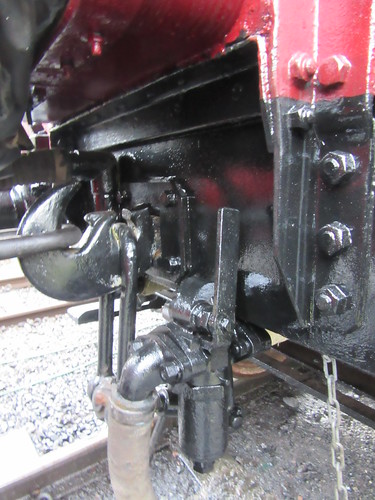
Restored coach 7828 at Rowsley: View showing coach drawhook, with unused coach 'D' link hanging down. The rest of the stowed coach screw coupling is obscured by the steam heating hose. The coach has been attached to 'Austerity' Tank 'Lord Phil' using the locomotive coupling.
Although screw couplings were effective, the results of accidents, particularly at higher speeds, showed the limitations of screw couplings. Part of the train could twist or even break free, increasing the chance of serious injuries.
Automatic Couplings
In other countries, various forms of 'Automatic' coupling had been developed to provide extra strength and simplify the business of coupling and uncoupling vehicles. In America, Eli Janney patented his design in 1873 and, in 1893, legislation made this the standard coupling in America. In 1915, John Willison of Derby patented his own automatic coupling which, with modifications, was adopted in 1935 by the Soviet Union as their standard coupler.
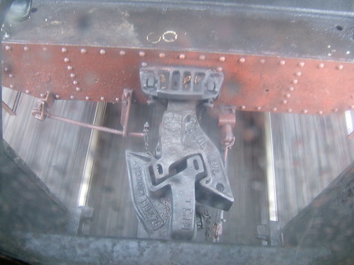
Ukraine Steam: Locomotive Em 735-72 at speed in the rain, showing Russian pattern autocoupler between tender & coach.
A variation of the Janney coupling with side release called the 'Buckeye' was adopted by the L.N.E.R. and the Southern in the 1930s, retaining side buffers. Since not all vehicles were fitted with 'Buckeye' couplings (and only one class of British steam locomotives was fitted - Gresley's 'A4'), the 'Buckeye' fitted to coaches was a 'drophead' pattern where the automatic coupler head could be lowered to reveal a conventional drawhook for use with a screw coupling. After the 1948 Nationalisation of British railways, a range of standard passenger coaches were built, similarly fitted with a conventional drawhook, 'drophead' 'Buckeye' coupler and adjustable side buffers (each with two positions - 'long' for use with a conventional screw coupling and 'short' when using the 'Buckeye').
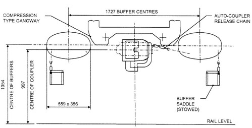
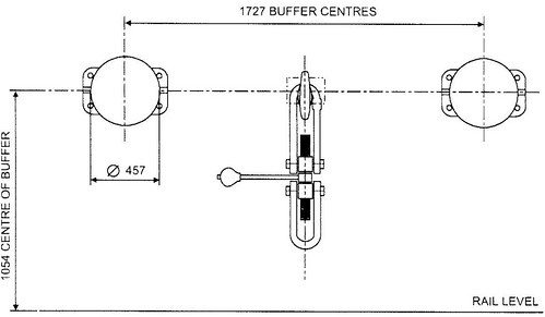
Buckeye Coupling as fitted to B.R. Mk 1 and Mk 2 gangwayed vehicles: End view (from a Railtrack document).
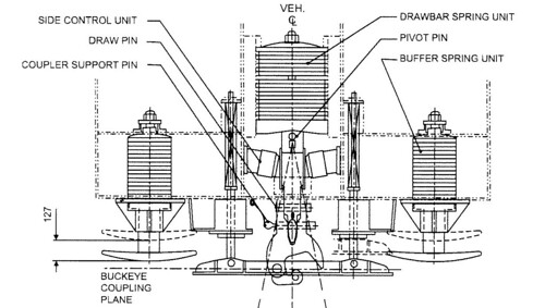
Buckeye Coupling as fitted to B.R. Mk 1 and Mk 2 gangwayed vehicles: Top view (from a Railtrack document).

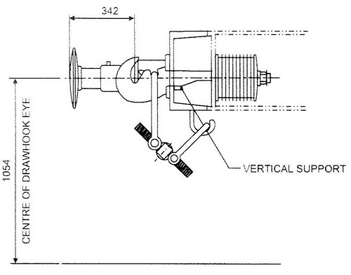
Buckeye Coupling as fitted to B.R. Mk 1 and Mk 2 gangwayed vehicles: Side view (from a Railtrack document).
The 'Buckeye' has a substantial hinging 'knuckle'. To couple, two vehicles are brought together with one of the knuckles in the 'open' position and the adjustable buffers set to the 'Short' position, as shown in the picture below.
BR Coaches being shunted together. Buffers in 'Short' position for use with Buckeye coupling. Unused 'saddles' are stowed on a bracket adjacent to each buffer.
As the two couplings contact, the open knuckle is forced closed and a mechanical latch drops, locking the knuckle closed. In addition to the shunter confirming visually that the 'pin' has dropped, a 'pull test' is conducted where the locomotive tries to separate the vehicles.
To uncouple, pulling a chain on either coupling head unlatches that knuckle, allowing the knuckle to swing open and the vehicles to be drawn apart.
When coupling or uncoupling the shunter stands alongside the vehicles and controls the movement by hand signals given to the driver of the locomotive performing the shunt. Unfortunately, to connect or disconnect the brake hoses and, when required, the steam heating hoses, the shunter still has to clamber underneath the vehicles, after coming to a clear understanding with the driver that it is safe to do so. The electrical jumpers between vehicles which allow the guard to control the carriage lighting also require connection/disdconnection.
Related posts on this website
The Role of the Shunter (Part 1).
On the Footplate (Part 2).
MIC - Brakes.
Mutual Improvement Classes (2) (List of MIC posts).
My photograph albums
Where necessary, clicking on an image above will display an 'uncropped' view or, alternately, pictures from may be selected, viewed or downloaded, in various sizes, from the albums listed:-
Passenger Rolling Stock.
['Related posts' amended 13-Apr-2020]
In 2013, the Brewood Village Garden Party annual event was restarted, re-located to the garden at Brewood Hall. Deemed a success, it has been held in 2014, 2015, 2016 and, as described below, on Saturday, 8th July 2017.
Preparations
Each year significant effort by volunteers, which starts months earlier with a series of planning meetings, is needed to ensure that people enjoy their visit to the event. In 2017, erection of the tents commenced two days before the Garden Party.
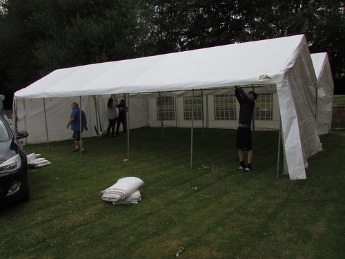
Brewood Garden Party 2017: The Refreshment Tent takes shape.
Preparations continued on the evening before the event. These included the erection of the large marquee which would serve as the 'Craft Tent'.
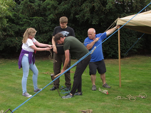
Brewood Garden Party 2017: Putting up the large Marquee.
The Event
Once again, the weather was kind on the day of the event and visitors started to arrive at the entrance gate a little before noon.

Brewood Garden Party 2017: The Admission table.
The Refreshment Tent was soon busy and remained busy. The combination of covered and open air tables, with the Pimm's Tent nearby, catered for all tastes.
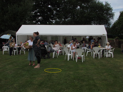
Brewood Garden Party 2017: The Refreshment Tent is always popular.
For the first time, food was also available from a 'Pizza Van' which used a traditional wood-fired oven. This was a very successful innovation and many people commented favourably on the quality of the pizza.
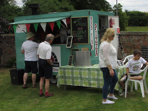
Brewood Garden Party 2017: A successful innovation in 2017 was the 'Pizza Van', using a traditional wood-fired oven.
Traditional entertainments included wet sponge throwing at a human target and the ever-popular coconut shy. There was also a catapult range and a supervised Under-5 Play Zone.
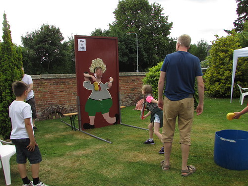
Brewood Garden Party 2017: Traditional entertainments included wet sponge throwing at a human target.
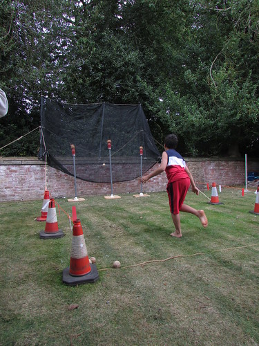
Brewood Garden Party 2017: The coconut shy is popular with all ages.
The Craft Tent featured the work of a number of local artists and crafters whilst the well-stocked Plants and Produce stall organised by the parish church provided shopping opportunities.
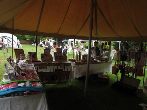
Brewood Garden Party 2017: The Craft Tent featured the work of a number of local artists and crafters.
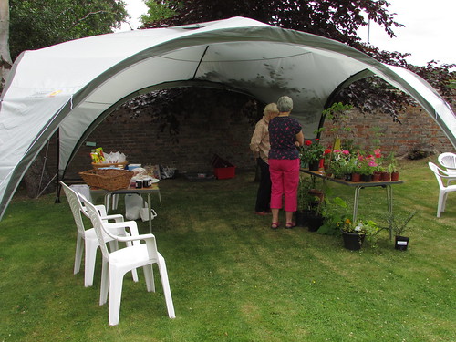
Brewood Garden Party 2017: The well-stocked Plants and Produce stall organised by the Parish Church provided shopping opportunities.
For the first time, Black Country Live Steamers displayed two marvellous live-steam scale models of traction engines, which created a lot of interest. You can read more about Black Country Live Steamers on their website here.

Brewood Garden Party 2017: Live-steam scale model of a Fowler traction engine, with a young admirer.
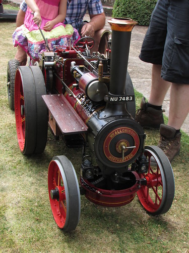
Brewood Garden Party 2017: Live-steam scale model of an Allchin traction engine.
An unexpected "visitor" was the preserved World War II Lancaster Bomber from the Battle of Britain Memorial Squadron, which overflew our event. You can read all about this historic arcraft on the website here.
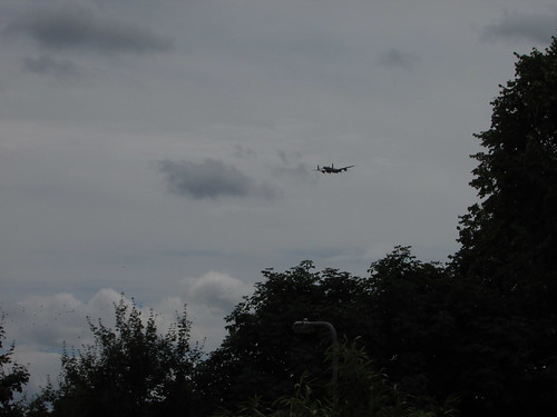
The preserved World War II Lancaster Bomber overflew the Garden Party.
As in previous years, live music was provided by the talented young musicians from the Cannock Wind Band and the Cannock Big Band who are based at the Cannock Performing Arts Centre.
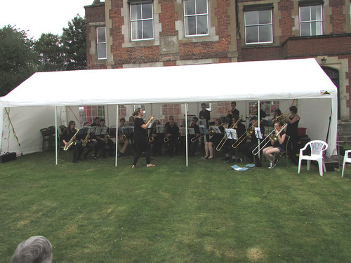
Brewood Garden Party 2017: Live music was provided by the Cannock Wind Band and the Cannock Big Band.
Later, a contingent from the Staffordshire Corps of Drums gave a demonstration. Captain Keates provided a virtuoso drum performance, accompanied by what I call a marching glockenspiel (but which I learn is also known as a Bell Lyre or a Lyra Glockenspiel - see Wikipedia here).
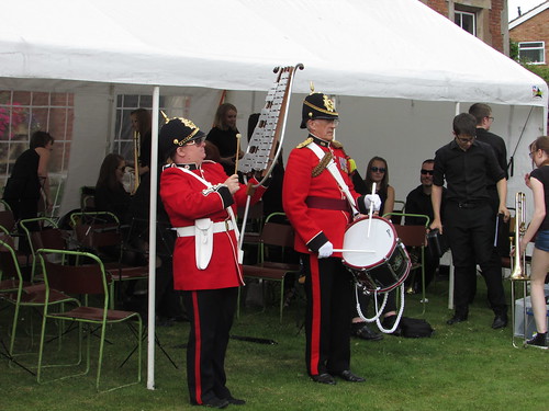
Brewood Garden Party 2017: A contingent from the Staffordshire Corps of Drums gave a performance.
As in previous years, a series of Sack Races and Egg and Spoon Races for children were held and, once again, proved popular. All the entrants were enthusiastically supported by the visitors. Each of the competitors was awarded a selection of confectionery,
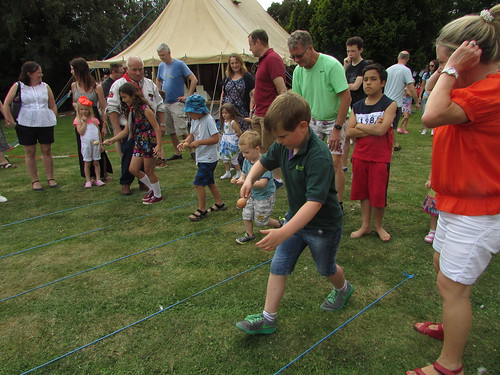
Brewood Garden Party 2017: The children entering the Sack Races and Egg and Spoon Races were enthusiastically supported by the visitors.
Everybody agreed that, once again, we'd had a very successful event (and the sun shone). This year, the organising committee made four awards - a special award to Compton Hospice and awards to Brewood Scouts, the Brewood Parish Church and the Jan Ford Foundation.
Reports on earlier garden parties at Brewood Hall
Brewood Vintage Garden Party 2013.
Brewood Vintage Garden Party 2014.
Brewood Garden Party 2015.
Brewood Garden Party 2016.
Related posts
More information on the charitable work supported by the Jan Ford Foundation in Myanmar (formerly Burma) can be found by following the links below:-
Education Support
Medical Support.
Pictures of the event
Where necessary, clicking on an image above will display an 'uncropped' view or, alternately, pictures from may be selected, viewed or downloaded, in various sizes, from the album below:-
Brewood Garden Party 2017.