skip to main |
skip to sidebar
Introduction
My first taste of the railways around Preston was on trips to Blackpool by excursion train. I've described one trip I made in 1957 in the post Halfex to Blackpool. I was impressed - multiple running lines, large LNWR-style signal boxes and signal gantries with many dolls, some still sporting LNWR lower quadrant arms. Once I started work, I didn't find the same opportunities to take this sort of trip, particularly after I started working for myself in 1966.
But in the late 1960s, following an initial visit to Preston area by light aircraft chartered by my client (described in the post My First Flight), we secured a contract to supply digital selective call equipment for Lancashire Constabulary. This involved making a number of trips to Preston by train.
Later, in connection with the West Coast Mail Line Electrification Project, a new Power Signal Box controlling the Preston area was commissioned in 1972/1973. My firm supplied certain telecommunications equipment for this project (there's a short post about the development phase here) so, once again, I made a number of trips to Preston by train.
Since then, I've made various trips to or through Preston by both road or rail.
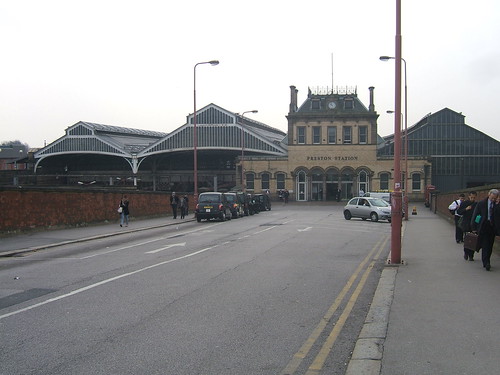 Preston station in 2011: View from the station approach looking south. Left train shed is over platforms 7/6, central train shed is over platforms 5/4 and right train shed (with the end heavily rebuilt) is over platforms 3/2.
 Preston: View from the footbridge looking south showing roof construction, with 'Pendolinos' in platforms 6 and 5.
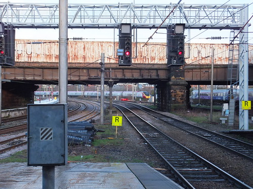 Preston: View looking north from platform 2 as an Up 'Pendolino' approaches.
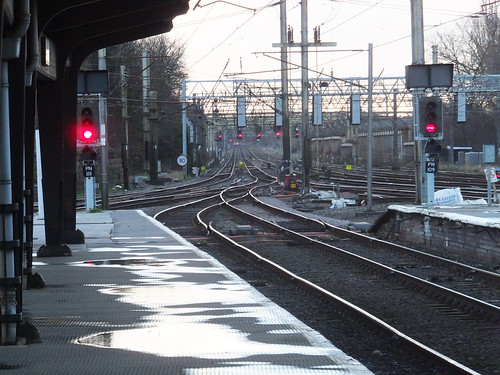 Preston Station looking south with Bay platforms 4c and 3c in the foreground.
History
Preston has a rather complex railway history. The notes below offer a simplified account.
The Preston & Wigan Railway received its Act in 1831 but, failing to attract sufficient financial support, it joined forces with the Wigan Branch Railway to form the North Union Railway. In 1838 its line was opened from Preston to Parkside, near Newton-le-Willows. This gave connections to the Liverpool and Manchester Railway (opened 1830) and the Grand Junction Railway (opened in 1837 and which, at the Birmingham end, linked to the London and Birmingham Railway). This was the start of Britain's railway network.
The next railway in Preston was a more modest affair. The Preston & Longridge Railway (opened 1840) was built mainly to ship stone from Longridge Fell for use in public buildings in Preston and for the construction of new docks in Liverpool. In the post Notes on Liverpool and its Docks I've written a little about the remarkable Jesse Hartley who was responsible for the high quality stonework provided in the expansion of Liverpool's Docks.
Extending north, the Lancaster and Preston Junction opened in 1840 but the North Union Railway initially made life very difficult by hampering through running. In the same year, the Preston & Wyre Railway, which sought to develop the Fylde area and complete a new port at the mouth of the River Wyre, opened its line. It, too, faced difficulties in through running to the North Union and both these lines opened their own, rather cramped, stations in Preston.
The Bolton and Preston Railway opened in 1843, sharing the North Union line for the 5.5 miles from Euxton Junction to Preston and offering a shorter journey from Preston to Manchester than via the North Union to Parkside and then via the Liverpool & Manchester. However, the high toll charged by the North Union for use of the shared line resulted in the North Union taking over the Bolton and Preston Railway the following year.
In 1844, both the Lancaster and Preston Junction and the Preston & Wyre trains were allowed to run into the North Union station. A direct line from Liverpool via Ormskirk to Preston was being promoted at the time, causing the North Union to feel threatened. It sought amalgamation with the Liverpool & Manchester and the Grand Junction, but these negotiations fell through. Instead, in 1846, it jointly leased its lines to the Manchester & Leeds and the Grand Junction, finally being absorbed in 1888 by the respective successors of the lessors the Lancashire & Yorkshire Railway and the London & North Western Railway.
In 1846, a joint North Union/Ribble Navigation Company branch was opened to Victoria Quay, involving a gradient of 1 in 29. The branch was extended to the new Preston Dock in 1892.
The Liverpool, Ormskirk & Preston Railway received assent in 1846 but was swiftly taken over by the East Lancashire Railway which had already absorbed the Blackburn & Preston. The East Lancashire Railway had problems with tolls charged for entering Preston from its long-gone connection at Farington particularly since, by this time, the lessors of the North Union were the London & North Western Railway and the Lancashire & Yorkshire Railway! The East Lancashire Railway promoted a Bill for its own route to Preston which was opposed by both the North Union and Preston Corporation. The final settlement involved landscaping near the Ribble and a difficult, curving approach to an expanded North Union station which opened in 1850. In 1859, the East Lancashire Railway amalgamated with the Lancashire & Yorkshire Railway which built new connections to Farington Curve Junction from the Liverpool Line (in 1891) and from Lostock Hall (in 1908).
By this time, congestion at the main station was causing many problems but it was not until 1880 that a new station was built, with further expansion in 1902.
Meanwhile, the West Lancashire Railway from Southport reached Preston in 1882 with its own terminus on Fishergate Hill. The railway's ambitious plans for the future were not fulfilled and in 1897 the Lancashire and Yorkshire Railway took over and constructed a new line to allow Southport trains to use the main station.

Click on image for larger view
1913 Railway Clearing House map of lines in the Preston area.
Signalling
Just before the second world war, two Westinghouse Style 'L' frames had been ordered, one to deal for the north end of the station, one for the south end. The war cancelled the project and most of the manual boxes struggled on until the present Preston Power Box took over in 1972/1973. One of the Style 'L' frames was used in the Euston resignalling but it was replaced quite soon by the Euston Power Box.
Of course, the manual signalling and the LNWR signal boxes which survived until the 1970s delighted me. I can remember standing on the Up main platform one evening waiting for a connection, just feet away from Preston No. 3 box. Every block bell could be heard clearly and I watched with interest every movement made by the signalman. Until Preston Power Signal Box was commissioned, these were the signal boxes on the main line approaching Preston from the south:-
Euxton Junction (84 lever)
Euxton Coal Sidings (20 lever) Closed in 1965
Leyland (30 lever)
Bashalls Sidings Closed in 1965
Farington Junction (90 lever tappet)
Farington Curve Junction (30 lever)
Skew Bridge (36 lever)
Ribble Sidings (50 lever)
Preston No. 1 (162 lever)
Preston No. 1A (30 lever)
Preston No. 2A (69 lever overhead)
Preston No. 3 (38 lever)
Preston No. 4 (184 lever tappet)
Preston No. 5 (126 lever)
These signal boxes are detailed in the John Swift plans (in [2] below):-
There were originally a number of other signal boxes on the various branches shown in the Railway Clearing House diagram above. The Southport - Preston lines were lost some time ago. I remember the sharply-curved East Lancashire line leaving Preston, but that too, was closed in 1972, freeing up valuable development land. Some of the signal boxes which dealt with East Lancashire line traffic are detailed in the John Swift plans (in [1] below):-
Lostock Hall Junction (40 lever)
Lostock Hall Carriage Sidings
Lostock Hall Station
Lostock Hall Engine Shed
Moss Lane Junction
Trains to the East Lancashire line are now routed via the main line to Farington Curve Junction, then crossing over the main lines to reach Bamber Bridge. From Farington Curve Junction, the Liverpool line survives as a 'long siding' as far as Ormskirk where a change to Merseyrail allows passengers to complete their journey to Liverpool.
 Preston Power Signal Box, commissioned in 1972/1973.
Related articles on other websites
There's a lot of useful information on the website Preston Station - Past & Present.
Preston station is now managed by Virgin Trains and there are some particulars here.
There are a number of articles on Wikipedia:-
Preston Railway Station.
London and North Western Railway
Preston and Wyre Joint Railway
Lancashire & Yorkshire Railway
East Lancashire Railway 1844–59
Track Diagrams
[1] ‘British Railways Layout Plans of the 1950’s - Volume 5: ex-Lancashire & Yorkshire Railway Lines in West Lancashire’ (ISBN: 1 873228 04 X).
[2] ‘British Railways Layout Plans of the 1950’s - Volume 6: West Coast Main Line (Euxton Junction to Mossband) and Branches’ (ISBN: 1 873228 00 7).
[3] ‘Railway Track Diagrams Book: 4 Midlands & North West’, published by TRACKmaps (ISBN 978-0-9549866-7-4).
Books
Not all of these books feature Preston itself, but they all have information regarding lines and traffic flows in the Preston area:-
‘A Regional History of the Railways of Great Britain: Volume 10 The North West’ by G. O. Holt, revised Gordon Biddle published by David & Charles (ISBN: 0946537 34 8).
‘The Railways around Preston – An Historical Review’ by Gordon Biddle (Foxline Publishing 1989) ISBN 1 870119-05-3.
‘Rails to the Lancashire Coast’ by Richard Kirkman and Peter van Zeller, published by Dalesman Books (ISBN: 1 85568 027 0).
‘Railway Stations in the North West’ by Gordon Biddle, published by Dalesman Publishing Co. Ltd. (ISBN: 0 85206 644 9).???
‘Railways of the Fylde’ by Barry McLoughlin, published by Carnegie Publishing,1992 (ISBN 0-948789-84-0).
‘Railways to the Coast’ by Michael H. C. Baker, published by Patrick Stephens (ISBN 1-85260-058-6).???
‘Railways in East Lancashire’ by Martin Bairstow (self-published 1988) ISBN 0 9510302 8 0.
‘Lost Railways of Lancashire’ by Gordon Suggitt, published by Countryside Books (ISBN: 9 781853 068010).
Related Posts in this Blog
Halfex to Blackpool (trip in 1957)
Railways around Blackpool (trip in 2014)
My Pictures
Railways around Preston
My mother was the born traveller. Whilst she managed a number of destinations in Europe, Poland (when part of the USSR: I accompanied her on this trip), Russia (when part of the USSR), the West Indies, Haiti, North America and Taiwan (accompanying me) she still wanted to see more but circumstances did not permit it. In contrast, at first I was much more timid.
In business, I had to travel and I made a number of trips to Europe, Hong Kong, Taiwan, Thailand and India. The trip to India in 1992 illustrated the problems of travel for business. Whilst I was in India for almost seven weeks, I only had two full days off. Of course, there were periods of free time of a few hours, but never enough to do more than see a little more of Delhi. I made good use of those two full days, travelling by train to Agra, with its Red Fort, Taj Mahal and nearby Fatepur Sikri on the one day and flying to Varanasi (formerly Benares) with the River Ganges on the other. There's an introduction to these early, mainly business, trips here.
After my partner, Daemon, passed away in 1999 I decided it was time I saw a little more of the world, before age, infirmity or poverty precluded such jaunts. With the limitations imposed by the earlier business trips in mind, I decided that, to give me the freedom to visit where I wanted, when I wanted, I would have to pay for my own travel. Let me say at once that I'm aware how fortunate I've been in being able to make these trips. There's an introduction to these more recent (and, I hope, continuing trips) here.
 The Potala Palace, Lhasa, Tibet.
With the advent of inexpensive digital photography, these more recent trips have given rise to quite a number of pictures (of rather variable quality) which you can find on my 'Flickr' site. There's an index of my travel pictures on my 'Flickr' site here or, alternately, you can choose a country from the list below and jump to a list of collections of pictures for that country.
Antarctic Peninsula: here (trips in 2007 and 2016)
Arctic: here
Argentina: here
Armenia: here
Australia (including Tasmania): here
Australia: (Thursday Island): here
Austria: here
Azerbaijan: here
Bali (Indonesia): here
Bhutan: here
Botswana: here
Brazil: here
Burma
2008 (1st trip): here
2008 (2nd trip): here
2009: here
2010: here
2011: here
2012: here
2013: here
2014: here
2015: here
2016: here
2017 (1st trip): here
2017 (2nd trip): here
2018: here
2019: here
Cambodia: here
Canada: here
Chile: here
China: here
Cuba: here
Dubai (U.A.E.): here
Equador (and Galapagos): here
Egypt: here
Falkland Islands: here
Georgia: here
Germany: here
Hong Kong and Macau: here
India: here
Japan: here
Java (Indonesia): here
Jordan: here
Laos:here
Malaysia (around KL): here
Malta: here
Mexico: here
Mongolia: here
Molucca Isles (Indonesia): here
Namibia: here
Nepal: here
New Zealand: here
Pacific Islands: here
Panama: here
Papua New Guinea: here
Peru: here
Qatar: here
Russia
2011: here
2012: here
Sabah (Malaysia):
2010: here
2015: here
Sarawak (Malaysia): here
Singapore: here
South Africa: here
Sulawesi (Indonesia): here
Taiwan: here
Thailand: here
Tibet (China): here
Turkey: here
Ukraine: here
United Kingdom: here
United Kingdom Overseas Territories:
(South Georgia) here
(St. Helena/Ascension Island) here
(Tristan da Cunha) here
United States of America: here
Vanuatu: here
Vietnam: here
West Papua (Indonesia):
here
Zambia: here
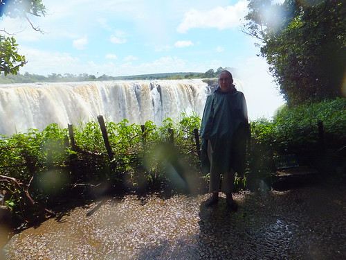 A rather damp Jan at Victoria Falls.
[Updated 16-Jan-2017: 28-Nov-2017: 19-Jun-2018: 9-Oct-2018: 28-Jun-2019: 30-Dec-2020]
The Danish physicist and chemist Oersted (1777-1851) is usually credited with the discovery that electric currents produce magnetic fields (there's a Wikipedia article here). In time, this simple observation led to the technological world of today.
Using an electric current to deflect a magnetised needle gave rise to the Electric Telegraph. Railways were one of the first users of the electric telegraph to allow communication over long distances.
The Single Needle Telegraph was based around two Polarised Galvanometers connected in series, one at the sending end, one at the receiving end. In a polarised galvanometer, an electric current flowing through a coil under the influence of a permanent magnet causes the movement of an armature carrying a pointer. Current in one direction deflects the pointer to the left, current in the opposite direction deflects the pointer to the right. The current is produced by two batteries, connected to the galvanometers by operating one of two switches. One wire is needed from the sending end to the receiving end, plus a return which can be the Earth (or, in the case of a railway, one of the rails).
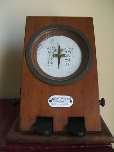
A Single Needle Telegraph Instrument from which Signalling Block Instruments were derived.
This idea was then adapted to give two adjacent signalmen an indication as to whether the line between them was occupied by a train or not. Provided the controlling signalman operated the switches correctly, the method worked well and the Block Signalling System remains in use today. There's an article describing one type of Block Signalling Instrument here.
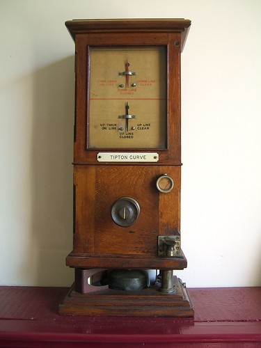
L&NWR type 'DN' Absolute Block Instrument.
Another application for Polarised Galvanometers was to confirm to a signalman the state of a semaphore signal which was out of sight, by fixing electric contacts to the signal arm to pass a current of one polarity if the arm was 'on', or opposite polarity if the arm was 'off'. Any position in between 'on' and 'off' passed no current, so that the signalman knew there was a problem. A similar technique was used to prove that the signal lamp was lit. There's an article here.
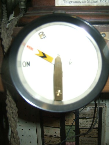
A polarised galvanometer arranged as a signal repeater for an upper quadrant semaphore distant signal.
The electro-mechanical Relay (often just called a 'Relay') is widely used in control systems in many forms. There's a useful introduction in Wikipedia here. A relay comprises a Coil and a pivoted Armature carrying one or more electrical Contacts. An electric current passed through the Coil produces an electromagnetic field which attracts the Armature. The movement of the Armature operates the Contacts which switch controlled circuits.
By using an electro-mechanical Relay to detect an electric current flowing through the rails, a method of detecting the presence of a train, called a Track Circuit, was developed and perfected in America. To provide the necessary safety, a d.c. current is circulated through the rails to operate a relay when there is no train present. When a train is present, the metal wheels and axle of a train 'shunt' part of this current, so that the relay releases and contacts on the relay can indicate that the track is occupied. Failure of the power supply or wiring cause the relay to release, indicating that the track is occupied, even if there is no train present. This type of design is called 'Fail Safe' and is a fundamental principle of railway signalling.
The relay itself must be highly reliable so that it cannot give a false 'Clear' indication, for instance, if contacts become 'welded'. Consequently, railway signalling relays tend to be more elaborate than relays used for less vital tasks. In this country, a common form of railway signalling relay was the 'Shelf Relay' with vertical Coils above a glass-sided chamber mounting the pivoted Armature and the Contacts, as shown in the picture below.
The picture shows a Shelf Relay for use in d.c. track circuits. It has a 9 ohm coil resistance and operates two 'Front' (normally open) and two 'Back' (normally closed) contacts. The rather odd terms used are because, on most designs, the terminals nearest the maintainer when mounted on a shelf (those at the front) connect to normally open contacts whilst those behind (at the back) connect to normally closed contacts. However, the design of the illustrated relay puts the 'Front' contacts at the back, but the terminals are clearly marked 'F' and 'B'.
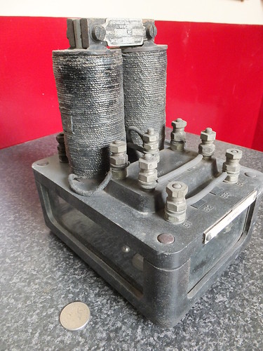
Neutral Track Relay ('Shelf' type).
Each relay carried a paper test label signed and dated by the tester recording the performance of the relay. Relays were usually 're-certified' every ten years. The two critical parameters for the above relay are recorded on the re-test label:-
Min P.U. 1.47 volts
Max D.A. 0.239 volts
The first (Minimum Pick Up) guarantees that the relay will not 'Pick Up' (operate) until at least 1.47 volts is applied to the coil, guaranteeing that spurious voltages will not operate the relay.
The second (Maximum Drop Away) guarantees that below 0.239 volts applied to the coil, the contacts will have 'Dropped Away' (released), proving that the contacts are not 'sticking'.
The introduction of track circuits gave rise to the need to mount relays in signal boxes or at the lineside and this was often done by providing a wooden cupboard with one or more shelves on which 'Shelf' relays sat.
The picture below shows a number of Shelf Relays wired as necessary.
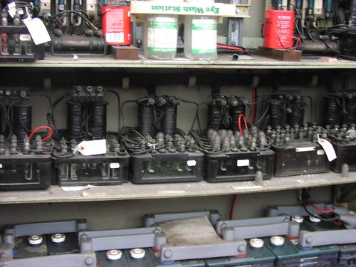 An elderly installation of shelf relays at Waterloo, prior to de-commissioning.
Simple relays, as described above, will operate the contacts whichever way the current flows through the coil. They were said to be 'neutral'. Some applications require a relay which is polarity-sensitive. This is achieved by incorporating a permanent magnet in the design so that the Armature only moves, operating the electric contacts, on one polarity of current. Current of the opposite polarity produces no movement. This type of relay has many applications in signalling control - for instance, 'proving' that a Block Instrument is displaying 'Line Clear' before allowing the signalman to release an electric lock on a signal lever.
 Style 'J' Polarised relay by Westinghouse Brake & Signal Co. Ltd.
This relay has two coils, each with 15,200 turns of insulated copper wire giving an electrical resistance of 500 ohms. The two coils are then wired in series, giving an overall coil resistance of 1000 ohms.
Everything is assembled onto the 'top plate' of bakelite (or similar). All external connections are made by connecting wires to the bolt-type terminals fixed to the 'top plate'.
The lower part of the case appears to be cast aluminium. In addition to the Westinghouse label screwed to the top plate, note the British Rail paper test label signed and dated by the tester recording the performance of the relay. The two critical parameters are recorded:-
Min P.U. .0055 Amps
Max D.A. .0033 Amps
The first (Minimum Pick Up) guarantees that the relay will not 'Pick Up' (operate) until 5.5 milliamps are flowing in the coil, guaranteeing that spurious currents will not operate the relay.
The second (Maximum Drop Away) guarantees that below 3.3 milliamps through the coil, the contacts will have 'Dropped Away' (released), proving that the contacts are not 'sticking'.
There are many other designs of relay for particular applications and many types of track circuit beyond the simple d.c. pattern.
In general, 'Shelf Relays' have been replaced by more modern designs but similar 'fail-safe' principles are incorporated. The 'BR930' is the generic reference for a range of more modern miniaturised plug-in relays still widely used on British and some overseas railways. These are widely known as 'Q' relays as this was the Westinghouse reference. A typical relay is illustrated below.
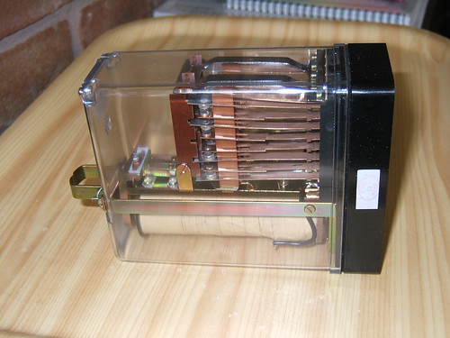 BR930 plug-in signalling relay made by Mors Smitt UK Ltd.
Even on modern relays, such as the 'BR930' plug-in relay, contacts are still referred to as 'Front' (or 'F') and 'Back' (or 'B'). The reduced relay size allows complex schemes to be assembled using large numbers of relays, as illustrated below.
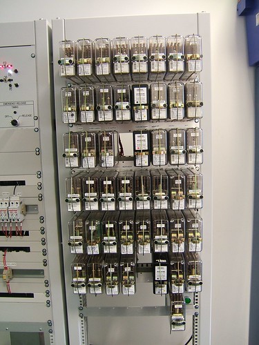
Relay control system on London Underground used for training purposes.
Overseas, different modern relay designs have emerged but intended to provide the same high integrity as British relays. As an example, the picture below shows an installation in Ukraine using Russian designed equipment.
 Signalling relay room, Mikulichin, Ukraine.
In the last few decades, railway signalling has undergone a revolution. The use of electronics is now widespread and Solid State Interlocking (SSI) is widely adopted and extensive areas are controlled from just a few signalling centres. This development has required the use of complex techniques to emulate the 'fail safe' properties of earlier systems. Except on lightly-used lines mechanical signalling is being eliminated.
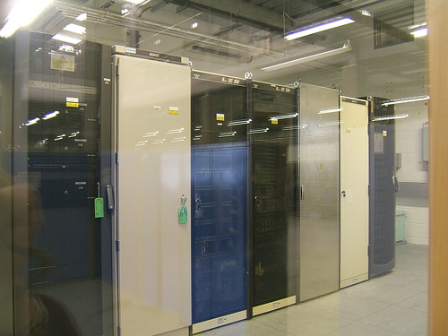 Solid State Interlocking equipment in a London Underground signalling training school.
Books
There are many, many books available on railway signalling. Here's a selection of some, generally older, books I've found interesting which include descriptions of the use of electricity in railway signalling:-
[ 1] ‘Power Railway Signalling’ by H. Raynar Wilson published 1908. (available from various sources as a reprint).
[ 2] ‘The Style L Power Frame’ written and published by J. D. Francis 1989 (ISBN 0 9514636 0 8).
[ 3] ‘Railway Signalling and Communications: Installation and Maintenance’ based on lectures to LNER staff in 1946. Reprinted Peter Kay ISBN 1 899890 24 6.
[ 4] ‘Fifty Years of Railway Signalling’ by O. S. Nock (Institution of Railway Signal Engineers) covering 1912-1962.
[ 5] ‘Two Centuries of Railway Signalling’ by Geoffrey Kitchenside/Alan Williams (Oxford Publishing Co.) ISBN 0 86093 541 8.
[ 6] ‘Railway Signalling: A treatise on the recent practice of British Railways’ edited by O. S. Nock (Adam & Charles Black, 1980) ISBN 0 7136 2067 6.
[ 7] ‘Railway Control Systems’ edited by Maurice Leach (A & C Black 1991) ISBN 0-7136-3420-0.
[ 8] ‘Single Line Control (British Practice’) by P. C. Doswell (Booklet 4, Institution of Railway Signal Engineers 1957).
[ 9] ‘Multiple Aspect Signalling (British Practice)’ by A. Cardani (Booklet 14, Institution of Railway Signal Engineers 1958).
[10] ‘Route Control Systems AEI-GRS’ by A. C. Wesley (Booklet 21, Institution of Railway Signal Engineers 1961).
[11] ‘Route Control Systems:- The S.G.E. 1958 Route Relay Interlocking System’ by J. V. Goldsbrough (Booklet 22, Institution of Railway Signal Engineers 1961).
[12] ‘Level Crossing Protection’ by P. A. Langley (Booklet 25, Institution of Railway Signal Engineers 1961).
Related posts on this website
There's an incomplete series of posts titled 'Railway Signalling in Britain', starting here, with links to subsequent posts.
There's an incomplete series of posts titled 'Spring Vale Electrical Controls', starting here, with links to subsequent posts.
There's yet another incomplete series of posts titled 'Princes End Electrical Controls', starting here, with links to subsequent posts.
There's a brief post here describing Russian-style all-electric signalling at Mikulichin, Ukraine.
Alternately, you can find all my posts on Railway Signalling (mechanical and electrical) here.
My pictures
British Railway Signalling Equipment.
Signalling at Mikulichin, Ukraine.
In my introductory post London Underground and Jan, I described how my interest in the Underground was sparked when my firm became involved in supplying tunnel telephone equipment.
One of the lines I've worked on is the Waterloo and City. At just under a mile and a half in length the Waterloo & City is the shortest of the London Underground railways now operated by Transport for London but it has a lot of interest.
In the post Waterloo Station, London (Part 2) I explained that the London & South Western Railway (L&SWR) which built the main line terminus at Waterloo had an ambition to extend their line eastwards. The Waterloo and City Railway Company was incorporated in 1893 by an Act of Parliament. Although independent from the L&SWR, no less than five of the eight directors of the new line were directors or employees of the L&SWR! Construction of the double-track Waterloo and City Line started in 1894 and it was opened, using electric traction, in 1898. It is 1 mile 46 chains long with two single-bore iron segment tunnels of varying diameter up to 12ft 9in.
The L&SWR operated the Waterloo and City railway from its opening, later purchasing the line outright. At the Grouping, the line passed to the Southern Railway and, upon Nationalisation, to British Railways, ending up part of London Underground in 2004. This history has produced a unique line.
Rolling stock has always been stabled and serviced at a cramped depot below ground level beyond Waterloo station. A siding just north of the Waterloo & City underground station was provided with a lift (built by Armstrong) to the main-line sidings, allowing underground vehicles to be transferred to and from the main lines. The railway generated its own electricity at a power station adjacent to the depot and the Armstrong Lift was also used to receive wagons of coal for the power station. The Armstrong Lift was removed to allow construction of the Waterloo International platforms to serve the Eurostar services, since when the Waterloo & City has been completely isolated from other railways.
The L&SWR started to electrify its suburban main line network from Waterloo in 1915, constructing a large, new power station at Wimbledon to supply the power. The sub-station at Waterloo main line station was arranged to also supply power to the Waterloo & City line.
As part of a comprehensive modernisation by the Southern Railway in 1940, the bare copper 'pinch-wires' which form part of the present tunnel telephone system were added. This system allowed the driver to communicate with the signalman at Waterloo (Waterloo & City) and the power supply operator in the main line substation at Waterloo. In 1972, control of the main line substation at Waterloo was transferred to Raynes Park. The original tunnel telephone control panels were left in Waterloo main line substation but the telephone circuits were extended to Raynes Park and a remote reset facility for the tunnel telephones was provided through the electro-mechanical telemetry system for power control.
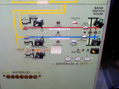 The Electric Control Room at Raynes Park presently controls traction power to the Waterloo & City. This view shows the small part of the large mimic diagram relating to the Waterloo & City.
At present, traction power is still provided from the Network Rail Main Line Traction Substation via d.c. track feeder cables. There are two tunnel traction sections, one for the Down or Westbound line (section 700), one for the Up or Eastbound line (section 701) line. The Waterloo Depot area, which is not provided with tunnel telephones, forms a third traction section (section 702). Traction sections are fed via high-speed d.c. circuit
breakers, similar to London Underground standard practice. At the remote end of the Up and Down lines, Bank, a Track Paralleling Hut was provided to minimise voltage drop. However, this feature was never commissioned and the railway operates as two single-end fed traction sections.
A new Traction Substation is being completed within Waterloo station near the Waterloo & City line and, once this is commissioned, the Network Rail Main Line Traction Substation will no longer be involved in the operation of the Waterloo & City line.
In 1989 Network South East, who were by then responsible for the line, ordered replacement rolling stock of the LUL Central Line pattern, providing five 4-car sets. Cranes were needed to remove the old rolling stock and deliver the new trains to the depot area, since the Armstrong Lift had been removed as mentioned above. Some civil works were needed to accommodate the new stock and the current collection system was changed from third rail to standard London Underground fourth rail pattern in 1992.

Present Waterloo & City vehicle.
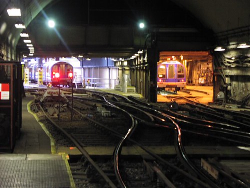 The depot at Waterloo, viewed from the Arrival platform, in 2004.
Westinghouse replaced the old signalling system in 1992 with a relay interlocking controlled from an 'NX' mosaic panel.
 The 'NX' signalling control panel at Waterloo in 2004.
Around 2007, a new Service Control Centre was constructed within Waterloo station. This was provided with a solid-state signalling interlocking system controlled from workstations. The 1992 Westinghouse signal box has been retained as an Emergency Service Control Centre.
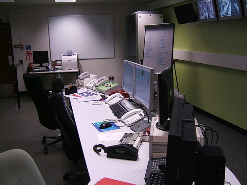 The present Service Control Centre at Waterloo.
Related information on other websites
Clive's UndergrounD Line Guides form an excellent reference to all of London Underground. The Guide for the Waterloo and City line is here.
There's a Wikipedia article here.
Related posts on this website
All my posts on London Underground can be found here.
Books
In my introductory post London Underground and Jan, there's a list of books about London Underground. From this list, these two are of particular relevance to the Waterloo and City Line:-
[ 1] 'The Waterloo & City Railway' (a very detailed history running to over 460 pages).
[ 2] ‘Railways of Waterloo’ (covers both the Waterloo & City and the main line station).
For a track diagram with other information, refer to another book included on the list in the introductory post here:-
[13] 'Railway Track Diagrams Book 5: Southern and TfL' Third Edition, published by TRACKmaps (ISBN 978-0-9549866-4-3).
Pictures
Waterloo & City.
[Flickr ref updated 3-May-2020]

(Click on map for larger view)
London Underground Map 2015 (Transport for London).
When I was quite young, I was introduced to the London Underground on a visit to London with my parents. I think I was terrified and fascinated in equal parts. Terrified by the speed, the noise and descending into the bowels of the earth to board the trains - fascinated by the frequency of trains and the relative ease of moving underground around London. As an adult, I was happy to utilise the tube but it never had the attraction of steam railways. Even after my firm started supplying special-purpose telephone equipment for railways in various countries, I saw the London Underground network merely as a means of transport, not a potential source of work.
That changed in, I think, 1995 when one of our major customers, who was bidding for a large telecommunications package in connection with the Jubilee Line Extension Project, asked us to quote for the design and supply of Tunnel Telephone equipment. Well, I had a vague idea of what was involved - most people travelling on the Tube notice the pair of bare wires carried on the tunnel wall forming part of the tunnel telephone system. These wires allow the driver to attach a portable telephone in case of emergency. None of the telephone systems we'd produced seemed adaptable to this tunnel telephone application and I thought that the costs of developing suitable equipment from scratch would make any offer we made unattractive. So we declined to quote, explaining our reason to our customer.
However, a few months later the customer came back to us, saying they'd really like us to quote, and this time we produced a quotation. Some time later (these things always seem to take an inordinate time to come to fruition - a large quotation we did for Brazil only produced an order after seven years!) we agreed a contract to design and supply the necessary tunnel telephone equipment for the Jubilee Line Extension. I then embarked on a fairly steep learning curve to better understand both the traction supply system on London Underground and the requirements for tunnel telephone systems. As we produced the necessary equipment, I became far more interested in the history and development of the London Underground system. Over the years since, I've worked on tunnel telephone systems for a number of the London Underground lines and, as time permits, I'll add more posts on this unique mass transit system.
Brief Introduction
The London Underground employs a fairly unusual fourth-rail system of electrification. I've written a little about how traction current is distributed in the post London Underground - Traction Power Distribution and there's a short background in the post Fourth Rail Electrification.
Tunnel Telephone systems used on London Underground have two functions - to discharge traction current in an emergency and allow the driver to talk to the Line Control Centre (now generally called the 'Service Control Centre'). The tunnel wires allow a driver to open the cab window and simply 'pinch' the two bare wires together (the bare tunnel wires are sometimes referred to as 'pinch wires'). This action automatically discharges the local traction section. Connecting a portable telephone to the exposed wires similarly discharges the traction section, after which a conversation with the control centre is possible. Fixed telephones with a similar function are provided at strategic locations (such as the Headwalls at stations). London Underground now call the Tunnel Telephone system the Emergency Traction Current Discharge System (ETCDS) to better-reflect its principal function. Providing speech with the control centre, in this age of Secure Cab Communication by radio, is the secondary role.
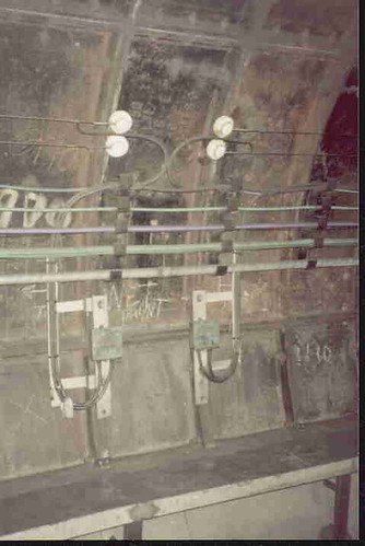
Jubilee Line: Tunnel wires mounted on cast iron tunnel lining at the junction of two adjacent Tunnel Telephone sections.
Clive's UndergrounD Line Guides form an excellent reference to all of London Underground.
For track diagrams of London Underground, refer to 'Railway Track Diagrams Book 5: Southern and TfL' Third Edition, published by TRACKmaps (ISBN 978-0-9549866-4-3).
Books
Here's a list of some of the books I've acquired dealing with London Underground:-
[ 1] 'The Waterloo & City Railway' by John C. Gillham (The Oakwood Press) ISBN 0 85361 544 6.
[ 2] ‘Railways of Waterloo’ by J. N. Faulkner (Ian Allen Publishing) ISBN 0 7110 2237 2.
[ 3] ‘London’s Local Railways’ by Alan A Jackson (David and Charles) ISBN 0-7153-7479-6.
[ 4] ‘Steam to Silver – An illustrated history of London Transport railway surface rolling stock’ by J. Graeme Bruce (London Transport) published 1970.
[ 5] ‘Inside Underground Railways’ by Alan A. Jackson (Ian Allen Ltd.) published 1964.
[ 6] ‘The London Underground – A diagrammatic history’ by Douglas Rose (Douglas Rose) 3rd edition ISBN 0 9507101 5 6.
[ 7] ‘Underground Train Overhaul – The Story of Acton Works’ by J. Graeme Bruce/Piers Connor (Capital Transport Publishing) ISBN 1 85414 134 1.
[ 8] ‘The Northern Line – An illustrated history’ by Mike Horne/Bob Bayman (Capital Transport Publishing) 2nd edition 1999 ISBN 1 85414 208 9.
[ 9] ‘The Story of London’s Underground’ (London Transport) revised edition 1966.
[10] ‘British Electric Trains’ by H. W. A. Linecar (Ian Allen) 2nd edition 1949.
[11] ‘Handling London’s Underground Traffic’ by J. P. Thomas (London Underground) published 1928.
[12] ‘The London Underground Tube Stock’ by J. Graeme Bruce (Ian Allen Ltd.) ISBN 0 7110 1707 7.
[13] 'Railway Track Diagrams Book 5: Southern and TfL' Third Edition, published by TRACKmaps (ISBN 978-0-9549866-4-3).
[14] ‘London Underground Guide 2015’ by Jason Cross (Train Crazy Publishing 2015) ISBN 978-1-907648-10-6.
Related posts on this website
All my posts on London Underground can be found here.
My pictures
My coverage of London Underground lines is very patchy and quality is generally rather poor, I'm afraid. All these albums are shown here.
[Book {14} added to book list 11-Apr-2021]
Jerome K. Jerome, best known as a humourist and writer, was born in Walsall in 1859. His most famous work 'Three Men in a Boat' was published in 1889.

Jerome K. Jerome in the 1890s (Photo: National
Media Museum @ Flickr Commons).
Jerome (whose middle name was Klapka) was given the Freedom of Walsall in 1926 (there's black-and-white film of the event here) and died the following year. Wikipedia has a useful biography here. For more information, go to the website of the The Jerome K Jerome Society.
Although I've known 'Three Men in a Boat' since childhood, I was only recently reminded that the book includes a description of taking the train from Waterloo during the period when the haphazard growth of the station had made it a laughing stock. Jerome's description is below:-
We got to Waterloo at eleven, and asked where the eleven-five started from. Of course nobody knew; nobody at Waterloo ever does know where a train is going to start from, or where a train when is does start is going to, or anything about it. The porter who took our things thought it would go from number two platform, while another porter, with whom he discussed the question, had heard a rumour that it would go from number one. The stationmaster, on the other hand, was convinced it would start from the local.
To put an end to the matter we went upstairs and asked the traffic superintendent, and he told us that he had just met a man who said he had seen it at number three platform, but the authorities thre said that they rather thought that train was the Southampton express, or else the Windsor loop. But they were sure it wasn't the Kingston train, though why they were so sure it wasn't they couldn't say.
Then our porter said the thought it must be on the high-level platform; said he thought he knew the train. So we went to the high-level platform and saw the engine-driver, and asked him if he was going to Kingston. He said he couldn't say for certain of course, but that he rather thought that it was. Anyhow, if he wasn't the 11.5 for Kingston, he said he was pretty confident he was the 9.32 for Virginia Water, or the 10 A.M. express for the Isle of Wight, or somewhere in that direction, and we should all know when we got there. We slipped half-a-crown into his hand, and begged him to be the 11.5 for Kingston.
'Nobody will ever know, on this line,' we said 'what you are and where you're going. You know the way, you slip off quietly and go to Kingston.'
'Well, I don't know, gents,' replied the noble fellow, 'but I suppose some train's got to go to Kingston; and I'll do it. Gimme the half-crown.'
Thus we got to Kingston by the London and South-Western Railway.
We learnt afterwards that the train we had come by was really the Exeter mail, and that they had spent hours at Waterloo looking for it, and nobody knew what had become of it.
In 1899 the London and South-Western Railway finally decided to rebuild the station (perhaps the gentle ribbing in 'Three Men and a Boat' played a part), although the work was not completed until 1922. There's a short description of the rebuilding of Waterloo Station here.
In 1956 'Three Men in a Boat' was made into a film which is described here. In 1975 the book was turned into a film for television, briefly described here. The television version can be watched on You Tube here.
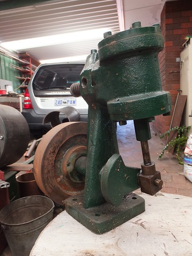
Over the years, the reciprocating steam engine has appeared in many forms. None is more unusual than the Oscillating Cylinder Engine. As the name suggests, the cylinder is arranged so as to pivot on the mounting frame. The piston rod connects directly to the crank, causing the whole cylinder to swing to and fro. The abutting mounting faces of the cylinder and mounting frame are provided with ports so that the movement of the cylinder opens and closes the appropriate ports to admit and exhaust steam at the correct time without the necessity for valve motion. Wikipedia has an article here which outlines some early industrial applications for this design.
Many people were introduced to oscillating cylinder engines through their use in live-steam toys made by 'Mamod'. Although I never had one of the models, I was fascinated by the simplicity of construction. I didn't realise how extensive the 'Mamod' range was until I read the Wikipedia article here.
In May 2011, my Friend Keith visited the U.K. and, on a visit to Peak Rail, we studied the 'vacuum motor'. This is powered by an Oscillating Cylinder Engine operating on vacuum from the locomotive’s braking system and, through suitable reduction gearing, can effortlessly turn the largest locomotive. There's a collection of pictures here.
On 13th February 2013 I visited Keith at his home in Perth, Western Australia. Keith had always been impressed with the simplicity of the ‘Oscillating Cylinder’ engine and he ran (on compressed air) an ‘Oscillating Cylinder’ engine he built many years ago to demonstrate how powerful this type of engine can be when properly engineered. There's a description of this part of my visit here.

Keith's demonstration 'Oscillating Cylinder' engine.
It wasn't until September 2015, when I was preparing the post Railway Turntables that I found that Messrs. Cowans, Sheldon & Co. Ltd. of Carlisle held a patent for this method of driving turntables by either vacuum or air from the braking system of the locomotive being turned.
Introduction
In 1971, I acquired Brewood Hall. It was in a fairly sorry state but, having done what repairs and redecorations could be afforded at the time, it became my family home. Over the years, more extensive conservation and redecoration work has been carried out as possible.
I started to research the history of the Hall and produced a small pamphlet summarising my findings (printed using an obsolete type of stencil duplicator called a 'Gestetner'). Early in 2008, this information was transposed into the internet posting here. As time permitted, I've carried out more historical research, assisted by friends.
This post is a collection of more recent findings. Historical information frequently contains errors, for a variety of reasons. Transcription errors may occur - particularly with old documents. Many books 'borrow' from other sources, with or without acknowledgement, sometimes allowing errors to perpetuate. Writers should cite the sources for information quoted, so that readers can form a view as to its likely accuracy. I'm afraid this rigour has not (yet) been applied to these notes, in the interests of assembling the information I've come across in one place, but there is an informal Bibliography at the end. Brewood Hall was always a rather minor estate so not too much information is recorded. Little is known with complete certainty.
The Victoria County History (often referred to simply as 'VCH') was founded in 1899, dedicated to Queen Victoria, and intended as "an encyclopaedic record of England's places and people from earliest times to the present day". Since 1933, it has been based at the Institute of Historical Research, University of London, modestly claiming to be "without doubt the greatest publishing project in English local history." The VCH covers most of England and is organised on a county basis. Staffordshire (in which Brewood is located) is covered in 14 volumes! Brewood appears in Volume 5, covering the East Cuttlestone hundred (the 'hundred' is an archaic county division, described in Wikipedia here). Fortunately, a digital version of this information is available at British History Online which was founded in 2003 by the Institute of Historical Research and the History of Parliament Trust, to provide "a digital library of key printed primary and secondary sources for the history of Britain and Ireland, with a primary focus on the period between 1300 and 1800".
The index for the digital version of the 'A History of the County of Stafford: Volume 5, East Cuttlestone Hundred' is here. The two sections most relevant to Brewood are:-
Brewood: Introduction, manors and agriculture
Brewood: Churches, schools and charities
Some information is held at the Staffordshire Record Office and the William Salt Library, both located in Stafford.
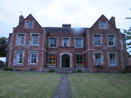 A summer evening at Brewood Hall in 2015.
Miscellaneous Notes
Hearth Tax
In the Hearth Tax Assessment of 1666, Brewood Hall was assessed at 10 hearths. There's an explanation of Hearth Tax here. Roehampton University, London runs the Centre for Hearth Tax Research and they maintain an on-line database at Hearth Tax Online covering some parts of England (but not Staffordshire).
Gardens and Orchards
Brewood Hall was a 'manor peculiar' without extensive land. Until the 1960s, there were about six acres of gardens and orchards. Following the sale to a property development company, around 5 acres were developed for housing, leaving about one acre with the Hall. Dr. Plot visited Brewood Hall, writing in 1686 that "In the whitethorn hedge, between the garden and the court before the house, were the figures of several animals, castles, etc., formed in topiary, and that in the orchard there was the whitethorn figure of a wren's nest, big enough to hold a man. In the garden was a yew tree, which formed an arbor, measuring five yards square outside and three and a half inside, cut on the top with loop and crest, like the battlements of a town, adorn'd at each corner with a pinnacle, over which is wrought a canopy two yards in diameter, which is carried up gradually to a small pinnacle". Near the pale of the orchard was a "fine yew tree, cut up gradually from greater to lesser rounds, to the number of twenty".
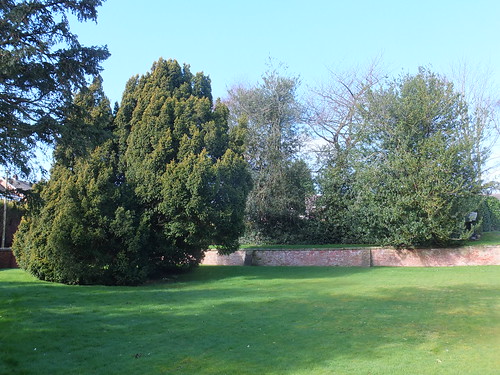 The Victorians swept away the topiary, but a massive, old yew tree still stands in remaining garden.
"The garden walls and gate pillars date from the late seventeenth century, as do some of the outbuildings. Stone fleurs-de-lis, about two feet high, which formerly surmounted each of the gate piers, are said to have been the origin of the mark used by John Turner, the famous Staffordshire potter, whose father once lived at the Hall. During the nineteenth century restoration, the fleurs-de-lis were removed to the back garden, and replaced by two large stone balls. On the north-east side of the Hall is a large early eighteenth century red brick farm building with king-post roof and exposed first floor beams. The building seems to have been used as a malthouse in the last century. The sandstone gateposts and steps of the former path to the rear of Brewood Hall still stand in Vicarage Road, a short distance from Sandy Lane. The house of Hall Farm Close stand on the site of a large pond which was filled in about 1960. The pond may have marked the site of Brewood Hall quarry, said to have been very deep, which was full of water before 1869." [reference 3].
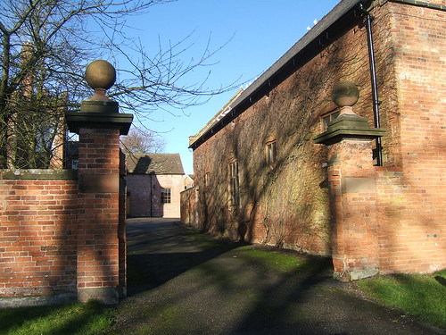 The main gate showing renovated gate piers with ball finials (prior to hanging of gates).
Period 1200 - 1786
Deer hunting was popular and King John is thought to have had a ‘Camera Regis’ (a temporary residence) on the site of Brewood Hall around 1204. The Fowke family became bailiffs of the Episcopal Manor of Brewood and Brewood Hall remained in this family for a number of generations. Brewood Hall was technically a 'Manor Peculiar' without extensive manorial lands. The Hall, gardens and orchards occupied only about six acres of land. "Brewood Hall is traditionally the site of King John's hunting lodge, and before the fourteenth century the semi-official residence of the bailiff of the Bishop's manor." [reference 3].
The pedigree of the Fowkes shows William Fowke living at Brewood Hall during the reign of Edward IV (1461-1483, with a brief interruption). During this period the ‘Leet’ (a Great Court) was held here.
Period 1786 - 1929
The Hall was owned by the Monckton's between 1786 and 1929 and the Turner family and others were tenants. In those times, landowners would often allow successive generations to be tenants, as long as the rent was paid.
Period 1929 - 1960
In 1929, Major R.P.F. Monckton sold Brewood Hall to Colonel C. O. Langley and it was the Langley family home for around 30 years. C.O. Langley was a partner in a solicitors practice (Fellows, Langley and Wright) in the town of Wolverhampton, about 8 miles from Brewood. He was also Borough Coroner and Stipendiary Magistrate in Wolverhampton. A son and daughter were brought up at Brewood Hall. Tragically, the son lost his life during the Second World War, whilst serving as a sub-mariner. His mother was unable to come to terms with the loss and became very reclusive. After the War, there were at least two part-time household staff. A housekeeper was accommodated in a modern cottage in Vicarage Road, about 5 minutes walk across the orchards which then lay at the rear of Brewood Hall. A gardner, handyman and chauffeur lived at Rambler Cottage, Sparrows End Lane, about two minutes walk from the Hall. Up until the 1960s, there was a substantial range of farm buildings next to Brewood Hall. Records indicate that Moncktons had an 'Estates Office' there in the 1950s, because they cite a fire at this office as the reason for not having the Title Deeds to a tract of disputed land in Coven.
Period 1960 - 1971
Following the death of his wife, C.O. Langley eventually decided to move to a smaller house in Wolverhampton. He disposed of Brewood Hall, with various outbuildings and the orchard, to Avion Properties in the 1960s. This company developed about five acres of the site for housing, resulting in the loss of some interesting buildings and all of the orchard, apart from one apple tree.
Until 1968, there was a large timber-framed barn with long straight braces to the lower panels. By the 1960s, it was in a very poor state of repair and, although there was an initiative to preserve the barn, it was not successful.
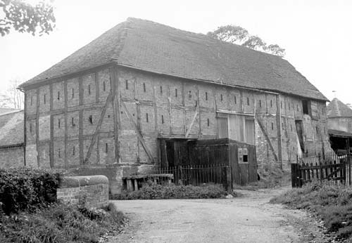 Large timber-framed barn at Brewood Hall, now demolished (Staffordshire Past Track).
The photograph below is taken from 'The Turners of Lane End' [reference 5] and shows the setting of Brewood Hall as it was prior to the development in the 1960s. The Hall itself, on the left, is little changed in appearance today but the remaining buildings are either swept away or altered. The large Barn on the right of the drive remains, but the twin gabled building in the foreground was demolished, along with the part 2-storey/part 1-storey barn extending to the right. Tragically, the large timber-framed barn on the right was also demolished. The gable roof of another, long barn runs across the rear of the picture. Only the left end of this barn survives.
 Brewood Hall circa 1960 (from 'The Turners of Lane End').
The photograph below, circa 1966 shows site as the changes were being made. The twin gabled building has been demolished, revealing the interior rear wall abutting the large barn. On the right, the part 2-storey and part 1-storey barn has gone. In the background, the long barn can been seen, but this was subsequently truncated.
 Brewood Hall circa 1966 during partial demolition of the outbuildings (Staffordshire Past Track).
This delightful hexagonal dovecote was also lost.
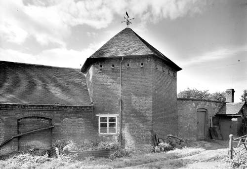 Dovecote at Brewood Hall, now demolished (Staffordshire Past Track).
Brewood Hall, the 'Big Barn', the truncated barn (now dubbed the 'Little Barn' and the brick garden walls had all been designated as 'Listed Buildings, Grade II' and the developers were thereby prevented from carrying out further demolition. However, the property remained empty for some time and significant vandalism had occurred. I have no doubt that, before long, the buildings would have mysteriously 'gone on fire', had not the property been purchased.
Period 1971 - Present
The Hall and remaining Big and Small Barns, with around an acre of gardens, were acquired by J. C. Ford in 1971. We didn't get the original deeds on purchase as C.O. Langley's Abstract of Title was sufficient. The Hall was in part-vandalised condition, so the priority was to preserve the fabric and try to get at least part of the building habitable. My mother, a close family friend and I lived here and did the initial redecorations ourselves. In 1979 my partner joined us so there were four of us here. Over the next ten years my mother and family friend died and a difficult financial period allowed the house to become rather run-down but then my fortunes revived. I nursed my partner through a long illness until he died in 1999. I then set about conserving and redecorating the house with professional help and my hope is that this very special place can be kept in its present reasonable condition.
The Monckton family are still major landowners in the area. Stretton Hall is now the 'family seat' but they still own Horsebrook Hall and Somerford Hall.
The Giffard family have been in continuous occupation of Chillington Hall (but not the same building) since the de Giffards settled after the Norman Conquest.
Photograph References
For my pictures around Brewood, including pictures of some of the tombs in the churchyard, click here.
Pictures of the interior of the Parish Church and some of its memorials are here.
To give an idea of the extent of the village, there is also a series of pictures taken from the tower of the church. These are here. A further set of pictures was taken from the roof of Brewood Hall and these are here.
For Historic Pictures of Brewood Village, click here.
For Historic Pictures of Brewood Hall, click here.
Links
Brewood (Wikipedia).
Brewood: A Short History by David Horowitz).
Fooks and Fowke Family Trees.
GENUKO Brewood Parish Register - 1834.
Brewood Genealogical Records (Forebears).
Free British Ancestry.
Dustydocs.com (Australia).
Staffordshire, England Genealogy (UKIsearch.com).
Staffordshire Past Track.
References
[1] 'A History of the County of Stafford: Volume 5: East Cuttlestone hundred' (1959), Victoria County History
[2] 'Brewood' by Mary E. Wakefield, published in 1972 by Praill (Cannock) Limited.
[3] 'Brewood' by David Horovitz, (ISBN 1 85421 175 7).
[4] 'History and Antiquities of Staffordshire' by Stebbing-Shaw'.
[5] 'Master Potters of the Industrial Revolution - The Turners of Lane End' by Bevis Hillier.
In the post Waterloo Station, London I gave a brief introduction to this important London terminus. The later post Visiting former 'Southern' stations in London describes the adjacent station of Waterloo East and its footbridge connection to the main station.
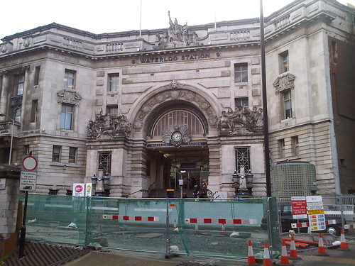 Waterloo: the imposing 'Victory Arch' is the main entrance for foot passengers, rather spoilt in this 2010 picture by the temporary works in the foreground. Three years later, there were still works going on in this area!
The entrance shown above leads to the main concourse through a passage lined with four dignified panels forming a 'Roll of Honour' in memory of London and South Western Railway employees who were killed in World War I.
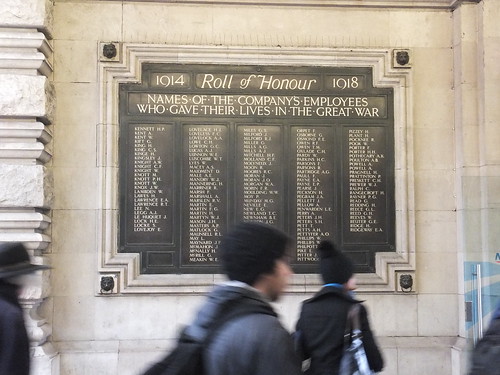 One of the four panels forming the WWI memorial.
The World War II memorial is a more modest affair.
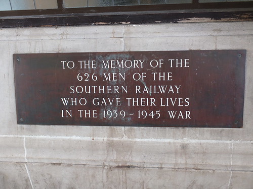 The WWII memorial.
There is also a memorial commemorating the 50th anniversary of 'D-Day', placed by Railtrack South East in 1994.
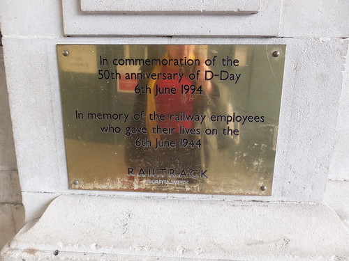 The 'D-Day' memorial.
My recent visit was on 13th September 2015 when I was involved in some alterations to the Tunnel Telephone system on the Waterloo and City Line. This time, I recorded the appearance of the 'Victory Arch' entrance from the concourse.

The main pedestrian entrance viewed from the concourse side.
The concourse side of the 'Victory Arch' is flanked by two imposing entrances leading to offices. The left hand entrance now leads to Network Rail offices but when I made a number of visits a few years ago it was the head office for 'Eurostar' and the words 'Eurostar House' can still be made out on the blue panel above the door.
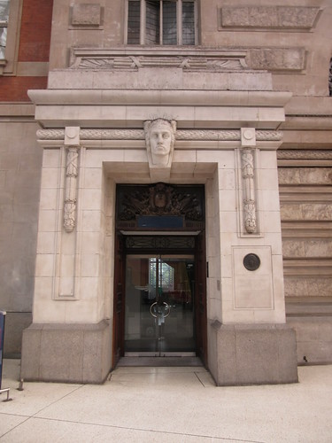
Entrance to what is now Network Rail offices, incorporating a memorial to Herbert Walker. The bust above the door now sprouts plastic spikes to discourage pigeons. The words 'Eurostar House' can just be made out on the blue panel above the door.

Detail of the memorial to Herbert Walker incorporating a stone cameo.
The memorial reads:-
HERBERT ASHCOMBE WALKER K.C.B.
LONDON & SOUTH WESTERN RAILWAY
GENERAL MANAGER 1911-1923.
SOUTHERN RAILWAY
GENERAL MANAGER 1923-1937.
DIRECTOR 1937-1947.
THIS STATION, THE DEVELOPMENT
OF THE DOCKS AT SOUTHAMPTON
& THE ELECTRIFICATION OF THE
SOUTHERN RAILWAY,
TO WHICH HE GAVE HIS GENIUS &
LEADERSHIP, ARE HIS MEMORIAL
This tribute gives a hint of this towering figure, who led first the L&SWR and then the Southern Railway from 1911-1937. There's a Wikipedia article here. The memorial lists Waterloo, Southampton Docks and electrification as his major achievements.
Regarding the first of these achievements, Waterloo: The L&SWR didn't intend the line to end here. The destination for many of their commuters was the City of London and the railway's ambition was to extend the line eastwards. But the best they could achieve was to operate the one and a half mile long Waterloo and City underground electric railway from 1898. They later purchased the railway (which subsequently passed to the Southern Railway and then British Railways, transferring to London Underground in 2004). Unwilling to accept that the station would remain a terminus, the L&SWR allowed the site to develop in a rather haphazard way which resulted in, effectively, three stations side-by-side - North, Central and South, as shown in the 1888 plan below.

Plan of Waterloo station in 1888 (Flickr Commons by the British Library).
Click on image above for larger view.
By the end of the 19th century the inadequacies of Waterloo had made it a laughing stock. A light-hearted description of the trials of catching the train at Waterloo appeared in the book 'Three Men in a Boat (written by Jerome K. Jerome and published in 1889)and is included in my post on Jerome here. In 1899, finally accepting that Waterloo would remain a terminus, the L&SWR obtained permission for a total rebuilding of the station. J W Jacomb-Hood (L&SWR Chief Engineer) was responsible for the structure and planning. After his death in 1914 A W Szlumper continued the work. James Robb Scott (L&SWR Chief Architectural Assistant) produced the architectural designs. The rebuilding was finally completed in 1922 with the erection of 'The Victory Arch'. This arch is the only part of the station buildings which are Listed (Grade II in 2002). The English Heritage description reads:-
The Victory or Memorial Arch was built 1919-22. It was designed as the main foot entrance to the station at the head of an impressive flight of steps, most of which is within the building. it is in the form of a triumphal arch some three storeys and attic in height, on the butterfly plan; the main arch being flanked by side bays and with one bay canted wings. It Was joined to the existing building on the left by a three bay section with recessed centre and giant order, this is not repeated to the right. Balustraded parapet with attic hidden behind. Stonework with heavy rustication in the centre. Sculpture - Bronze plaques under the arch bear the names of 585 LSWR employees who lost their lives in WWI, but the chief features are two sculptural groups, one dedicated to Bellona and dated 1914 and the other, dated 1918, to Peace, under the names of the greatest fields of battle set around a glazed arch set with a clock in a sunburst, and surmounted on the roof by Britannia. Prominent on the concourse side of the arch is the name of the company. The sculptor was the other wise little known Charles Whiffen. The special significance of the monument within the post-First World War genre is that the LSWR staff themselves were, uniquely, consulted on its design. Pylons with iron lamps flank the staircase.
The rest of the station is not of special architectural or historic interest.
The dismissal of the rest of the station as without interest is an unkind opinion shared by Nikolaus Pevsner who, in his 'Buildings of England: London' called the steelwork “sadly timid” and the facade “spoiled by a hopeless position”. Stuart Durant on The Victorian Web is more even in his judgement, writing "Waterloo, despite its architectural failings — in particular its vainglorious attempt at monumentality — is a pleasant and efficient station. For all the lack of bravura of the scheme, the glazed roofs of Jacomb-Hood and Szlumper give Waterloo some of the best natural lighting of any station." Personally, I consider Waterloo to be one of the more delightful survivals of London's railway terminals together with the rather more heavily modified candidates of King's Cross and St. Pancras. I certainly agree regarding the success of the glazed roofing.
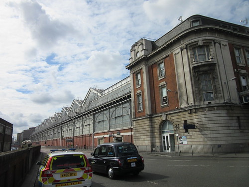 Station Approach looking south-west showing the curtain wall adjacent to platform 1 (left) and the east end of the main station building (right).
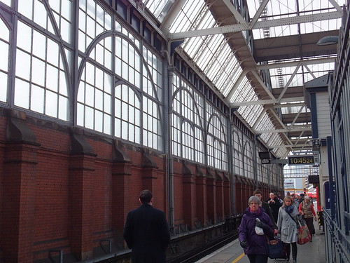 The curtain wall adjacent to platform 1.
I found one further war memorial: a simple tribute to the fourteen men of Nine Elms locomotive depot who "died by enemy action 1939-1945". I suspect that this memorial was originally located within the buildings of the Motive Power Depot and was re-sited at Waterloo when the Depot was abolished. It is now positioned on the wall adjacent to Starbuck's.
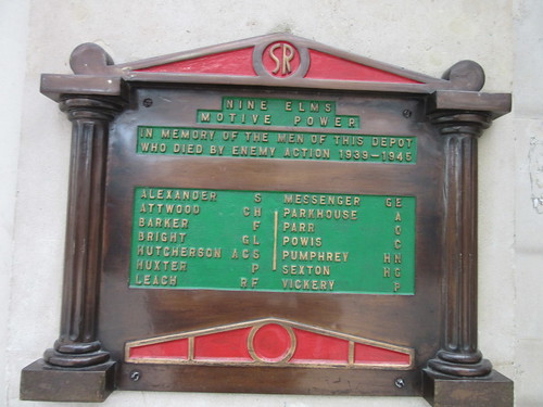 Nine Elms Motive Power memorial.
Before the rebuilding of the station, there was one little-used through line at the Central station which crossed Waterloo Road on a bridge and connected with the SE&CR line at what is now Waterloo East. The arrangement can be seen in the 1888 plan below.
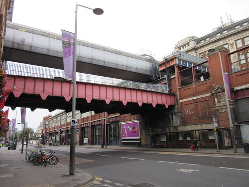 Waterloo Station, viewed from Waterloo Road. The overbridge originally carried a single line to Waterloo East and a footpath and now appears to be in use for cable drum storage. The more modern pedestrian bridge at a higher level now links Waterloo and Waterloo East.
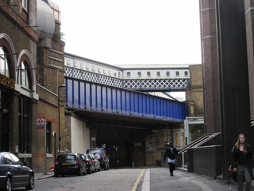 Sandell Street viewed from Waterloo Road. The blue bridge presumably carried the former connecting line to Waterloo East. The roof over the high level footbridge changes to the inelegant form shown, once clear of Waterloo Road!
There's a Wikipedia article on Waterloo Station here.
Network Rail are planning significant further expenditure to bring the rest of the International station back into use and extend platforms 1 to 4. The rather nice aerial view below accompanies their write-up here
 Waterloo Station from the air (Photo: Network Rail).
Click on image above for larger view.
My pictures
London: Waterloo Station
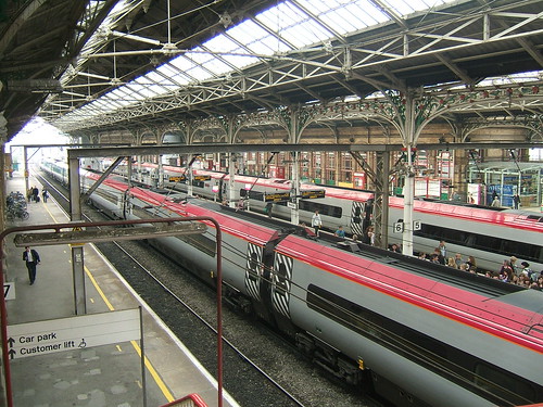 Preston: View from the footbridge looking south showing roof construction, with 'Pendolinos' in platforms 6 and 5.