skip to main |
skip to sidebar
In the post Waterloo Station, London I gave a brief introduction to this important London terminus. The later post Visiting former 'Southern' stations in London describes the adjacent station of Waterloo East and its footbridge connection to the main station.
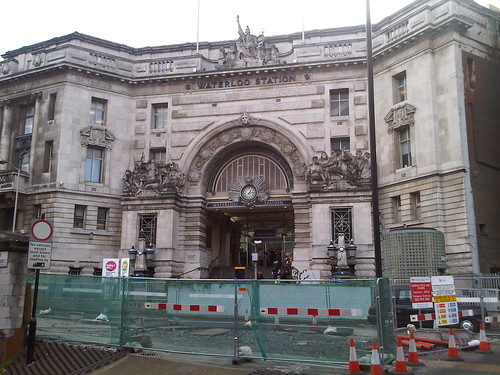 Waterloo: the imposing 'Victory Arch' is the main entrance for foot passengers, rather spoilt in this 2010 picture by the temporary works in the foreground. Three years later, there were still works going on in this area!
The entrance shown above leads to the main concourse through a passage lined with four dignified panels forming a 'Roll of Honour' in memory of London and South Western Railway employees who were killed in World War I.
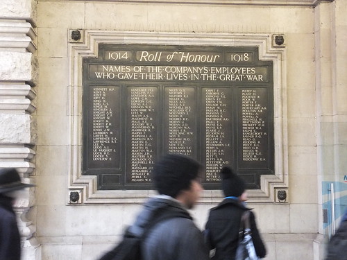 One of the four panels forming the WWI memorial.
The World War II memorial is a more modest affair.
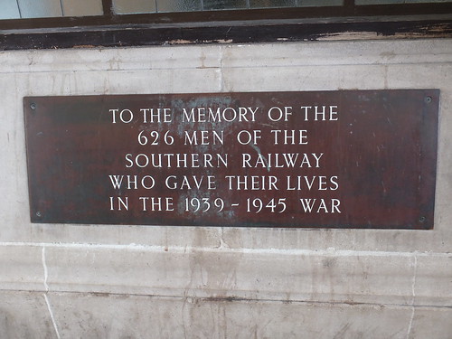 The WWII memorial.
There is also a memorial commemorating the 50th anniversary of 'D-Day', placed by Railtrack South East in 1994.
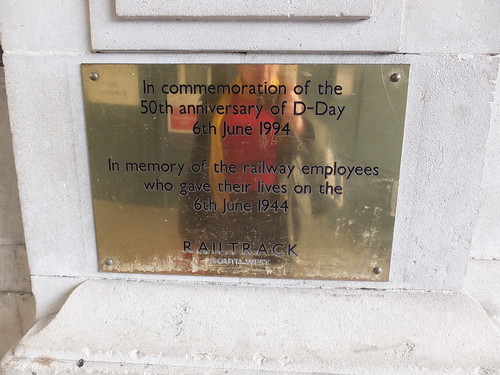 The 'D-Day' memorial.
My recent visit was on 13th September 2015 when I was involved in some alterations to the Tunnel Telephone system on the Waterloo and City Line. This time, I recorded the appearance of the 'Victory Arch' entrance from the concourse.

The main pedestrian entrance viewed from the concourse side.
The concourse side of the 'Victory Arch' is flanked by two imposing entrances leading to offices. The left hand entrance now leads to Network Rail offices but when I made a number of visits a few years ago it was the head office for 'Eurostar' and the words 'Eurostar House' can still be made out on the blue panel above the door.
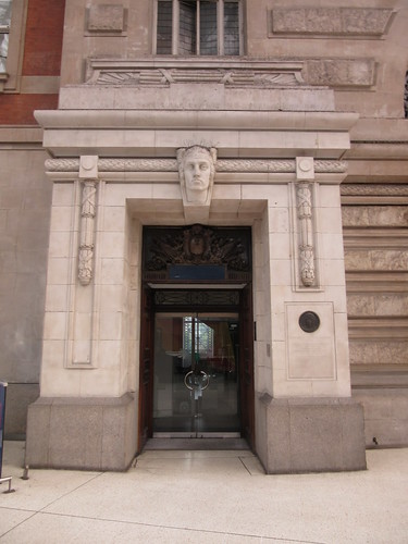
Entrance to what is now Network Rail offices, incorporating a memorial to Herbert Walker. The bust above the door now sprouts plastic spikes to discourage pigeons. The words 'Eurostar House' can just be made out on the blue panel above the door.

Detail of the memorial to Herbert Walker incorporating a stone cameo.
The memorial reads:-
HERBERT ASHCOMBE WALKER K.C.B.
LONDON & SOUTH WESTERN RAILWAY
GENERAL MANAGER 1911-1923.
SOUTHERN RAILWAY
GENERAL MANAGER 1923-1937.
DIRECTOR 1937-1947.
THIS STATION, THE DEVELOPMENT
OF THE DOCKS AT SOUTHAMPTON
& THE ELECTRIFICATION OF THE
SOUTHERN RAILWAY,
TO WHICH HE GAVE HIS GENIUS &
LEADERSHIP, ARE HIS MEMORIAL
This tribute gives a hint of this towering figure, who led first the L&SWR and then the Southern Railway from 1911-1937. There's a Wikipedia article here. The memorial lists Waterloo, Southampton Docks and electrification as his major achievements.
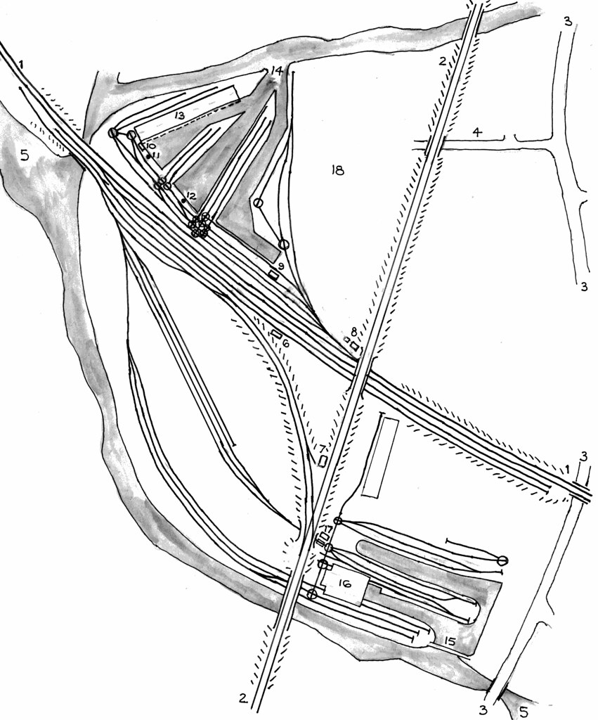
Regarding the first of these achievements, Waterloo: The L&SWR didn't intend the line to end here. The destination for many of their commuters was the City of London and the railway's ambition was to extend the line eastwards. But the best they could achieve was to operate the one and a half mile long Waterloo and City underground electric railway from 1898. They later purchased the railway (which subsequently passed to the Southern Railway and then British Railways, transferring to London Underground in 2004). Unwilling to accept that the station would remain a terminus, the L&SWR allowed the site to develop in a rather haphazard way which resulted in, effectively, three stations side-by-side - North, Central and South, as shown in the 1888 plan below.

Plan of Waterloo station in 1888 (Flickr Commons by the British Library).
Click on image above for larger view.
By the end of the 19th century the inadequacies of Waterloo had made it a laughing stock. A light-hearted description of the trials of catching the train at Waterloo appeared in the book 'Three Men in a Boat (written by Jerome K. Jerome and published in 1889)and is included in my post on Jerome here. In 1899, finally accepting that Waterloo would remain a terminus, the L&SWR obtained permission for a total rebuilding of the station. J W Jacomb-Hood (L&SWR Chief Engineer) was responsible for the structure and planning. After his death in 1914 A W Szlumper continued the work. James Robb Scott (L&SWR Chief Architectural Assistant) produced the architectural designs. The rebuilding was finally completed in 1922 with the erection of 'The Victory Arch'. This arch is the only part of the station buildings which are Listed (Grade II in 2002). The English Heritage description reads:-
The Victory or Memorial Arch was built 1919-22. It was designed as the main foot entrance to the station at the head of an impressive flight of steps, most of which is within the building. it is in the form of a triumphal arch some three storeys and attic in height, on the butterfly plan; the main arch being flanked by side bays and with one bay canted wings. It Was joined to the existing building on the left by a three bay section with recessed centre and giant order, this is not repeated to the right. Balustraded parapet with attic hidden behind. Stonework with heavy rustication in the centre. Sculpture - Bronze plaques under the arch bear the names of 585 LSWR employees who lost their lives in WWI, but the chief features are two sculptural groups, one dedicated to Bellona and dated 1914 and the other, dated 1918, to Peace, under the names of the greatest fields of battle set around a glazed arch set with a clock in a sunburst, and surmounted on the roof by Britannia. Prominent on the concourse side of the arch is the name of the company. The sculptor was the other wise little known Charles Whiffen. The special significance of the monument within the post-First World War genre is that the LSWR staff themselves were, uniquely, consulted on its design. Pylons with iron lamps flank the staircase.
The rest of the station is not of special architectural or historic interest.
The dismissal of the rest of the station as without interest is an unkind opinion shared by Nikolaus Pevsner who, in his 'Buildings of England: London' called the steelwork “sadly timid” and the facade “spoiled by a hopeless position”. Stuart Durant on The Victorian Web is more even in his judgement, writing "Waterloo, despite its architectural failings — in particular its vainglorious attempt at monumentality — is a pleasant and efficient station. For all the lack of bravura of the scheme, the glazed roofs of Jacomb-Hood and Szlumper give Waterloo some of the best natural lighting of any station." Personally, I consider Waterloo to be one of the more delightful survivals of London's railway terminals together with the rather more heavily modified candidates of King's Cross and St. Pancras. I certainly agree regarding the success of the glazed roofing.
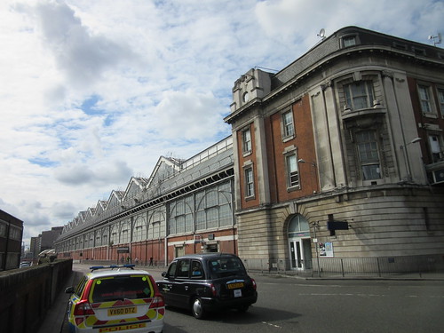 Station Approach looking south-west showing the curtain wall adjacent to platform 1 (left) and the east end of the main station building (right).
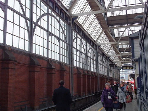 The curtain wall adjacent to platform 1.
I found one further war memorial: a simple tribute to the fourteen men of Nine Elms locomotive depot who "died by enemy action 1939-1945". I suspect that this memorial was originally located within the buildings of the Motive Power Depot and was re-sited at Waterloo when the Depot was abolished. It is now positioned on the wall adjacent to Starbuck's.
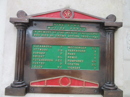 Nine Elms Motive Power memorial.
Before the rebuilding of the station, there was one little-used through line at the Central station which crossed Waterloo Road on a bridge and connected with the SE&CR line at what is now Waterloo East. The arrangement can be seen in the 1888 plan below.
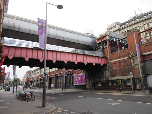 Waterloo Station, viewed from Waterloo Road. The overbridge originally carried a single line to Waterloo East and a footpath and now appears to be in use for cable drum storage. The more modern pedestrian bridge at a higher level now links Waterloo and Waterloo East.
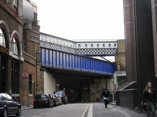 Sandell Street viewed from Waterloo Road. The blue bridge presumably carried the former connecting line to Waterloo East. The roof over the high level footbridge changes to the inelegant form shown, once clear of Waterloo Road!
There's a Wikipedia article on Waterloo Station here.
Network Rail are planning significant further expenditure to bring the rest of the International station back into use and extend platforms 1 to 4. The rather nice aerial view below accompanies their write-up here
 Waterloo Station from the air (Photo: Network Rail).
Click on image above for larger view.
My pictures
London: Waterloo Station
TURNTABLE ORIGINS
The turntable (or 'turnplate') appeared early in the development of railways, initially as a means of routing single wagons from one line to another at coal mines and similar installations and often narrow-gauge.
 A cast narrow-gauge wagon turntable preserved at Black Country Living Museum (without the approach tracks).
When the first steam railways were built, the size of turntables was increased to allow shunting of passenger coaches and turning of the small locomotives then in use. No passenger station lacked a battery of turntables to assist in marshalling each train. The 'Roundhouse' design of locomotive shed using a turntable to access a number of radiating stabling roads was used as early as 1846 by the London and Birmingham Railway (there's a very brief description of that line here). The building of the roundhouse locomotive shed built at Camden survives as a Grade II* listed building and is now used as a performing arts and concert centre called Roundhouse. There are brief details of the building on Jack Whitehead's Local History website here.
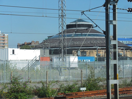 Camden, showing the London and Birmingham locomotive roundhouse of 1846 (now the Roundhouse Theatre).
Eventually, small turntables became confined to goods yards and canal interchanges. They were often provided in large numbers, sometimes associated with capstans so that haulage ropes could be arranged allowing horses to move the wagons. The sketch map below shows the sidings and wagon turntables at the canal interchange basins at Bloomfield in the West Midland area of England in the early years of the 20th century.
 A larger version of this sketch can be found here.
There's a brief write-up about the canals and sidings at Bloomfield in the post Rail and Canal at Bloomfield.
The picture below shows a typical standard-gauge wagon turntable, this one preserved in Birkenhead Docks.
 Birkenhead: Wagon Turntable adjacent to Duke Street Lifting Bridge.
There's a write-up of my exploration of Birkenhead's Docks in the post Birkenhead and New Brighton by train (Part 2).
LOCOMOTIVE TURNTABLES
Developments in locomotive design produced larger engines which required longer turntables. In Britain, turntables up to 70 feet in length were made. There's a Wikipedia article here.
The following description is based on an article published in The Locomotive Magazine and Railway Carriage and Wagon Review, dated 15th February 1937. This article, in turn, was 'a brief abstract of the main points mentioned' in a paper on Locomotive Turntables read to a meeting of the Institution of Mechanical Engineers on 27th January 1937 by Associate Member Mr. J. H. A. Wilkins.
Modern locomotive turntables conform to one of three types:-
1. The cantilever, or centre balanced type: either 'through' or 'deck' pattern.
2. Articulated or centre hinged type.
3. Continuous girder type supported at three points (Mundt type).
Of more than 900 turntables in use in 1936, most were centre-balanced type with only around 20 ar and 20 of the continuous girder (Mundt) pattern. In the U.K, the largest turntable in use is 70 ft. diameter.
1. Cantilever or centre balanced type supported on the centre pivot
The turntable is balanced in the centre, the main girders acting as cantilevers. Two strong wrought iron or steel plate main girders are braced together by stretchers and securely attached to a middle framework which rests on and revolves around a centre pin fixed to a solid foundation. Large carrying wheels which travel on a rail laid round the circumference of the pit are attached to both ends of the main girders.
In use, the locomotive to be turned is centred or 'set' so that the majority of the weight is taken by the centre pivot, and a small force applied to the ends of the main girders is able to turn the table. To assist in achieving the necessary balance, the length of the table should be several feet longer than the wheel base of the locomotive.
During erection, the large carrying wheels are given a slight clearance from the circumferential rail and carry that part of the weight not supported by the centre pivot.
If a locomotive is perfectly balanced, all the weight is carried by the centre pivot, otherwise part of the weight is supported by the large carrying wheels at one end of the turntable.
The centre pivot comprises a cap or yoke cast in steel which supports the main girders by large suspension bolts. The cap rests on a pivot bearing, typically made of 'UBAS' case hardening steel supporting a bronze, gun-metal, or steel cup ('UBAS' was a trade mark used by W. T. Flather who manufactured special steels). If an anti-friction thrust bearing is incorporated, this is enclosed in a steel housing resting on, and positioned on, the stump or centre pivot. The centre pivot takes the full load of the turntable and locomotive when in use and is usually cast iron, secured by rag bolts or similar to a solid, normally concrete, foundation.
Because of the clearance given to the large carrying wheels, 'blocking pads' are provided to take the weight of the locomotive when running on or off the turntable. In some cases the hand lever for operating these blocking pads also operates the locking bolts for holding the table in position opposite the various roads radiating from the pit. In its horizontal position this lever is sometimes used for turning the table manually.
In some designs, levers to operate the blocking pads and locking bolts are replaced by hand wheels at each end of a shaft running the whole length of the turntable girder, so that turning the hand wheel at either end operates the blocking pads and locking bolts at both ends. The locking bolts also serve as blocking pads in some designs, engaging in a cast iron locking rest fixed in the pit wall where each track radiates.
The centre-balanced main girder may be of 'deck' (under girder) or 'through' (over girder) design.
In the 'deck' type, the rails are laid upon the top of the main girders, simplifiying construction but requiring a deep pit to accommodate the height of the main girders.
In the 'through' type, the rails are laid between the main girders, carried on cross members. This allows the use of a shallower pit. The G.W.R. normally use the 'through' type in outside locations (a 65 ft. turntable on the GWR at Oswestry was cited as an example) where a notice visible to the engineman reads "All engines must stop before going on to the turntable." so as to avoid shock as the locomotive runs on to the table, due to the clearance on the large carrying wheels). The 'through' type, although possessing the advantage of requiring only a shallow pit, weighs considerably more itself due to the heavier construction and greater width, and costs more than the 'deck' type.
2. Articulated or centre hinged type supported at three points
This design is credited to a Chief Inspector of Locomotives on a German railway called Herr Klensch who sold his patent to Messrs. Julius Vogele in Mannheim. They, in turn, granted licences to manufacturers in Germany and elsewhere.
The articulated turntable is divided into two beams, supporting the load over the centre pivot and the large carrying wheels at each end of the turntable which are always in contact with the circumferential rail. The large carrying wheels take at least half of the load on the turntable and it can be driven from either end.
Because the large carrying wheels remain in contact with the rail, the ends of the table are not violently depressed when a locomotive runs on to it, reducing the shocks which occur with the cantilever or centre balanced type descried above in which, when correctly balanced, the large carrying wheels remain clear of the rail.
One advantage of dividing the main girders in this design is that girder height can be reduced, allowing the use of a shallower pit.
The articulated or centre hinged design found favour in the U.S.A. where lattice girders were often used. Elsewhere riveted plate girders or rolled girders were generally used.
With an evenly-distributed load, the thrust bearing of the centre support carries half the total load the balance being carried by the large carrying wheels. The centre joint must be sufficiently robust to prevent slackness occurring which allows the large carrying wheels to skew, increasing the resistance to turning when the table is driven from one end only. A number of designs of centre joint using flexible hinge plates and laminated spring joints were evolved.
3. Continuous girder type supported at three points (Mundt type)
Mundt was an engineer with the Dutch State Railways and his improvement of the centre-hinged type eliminated the centre hinge by allowing a continuous girder to deform under load. The continuous girders are not of uniform section throughout, but are reinforced from each end to a certain distance short of the centre pivot. This allows of sufficient flexibility to prevent the rising of the unloaded end of the table with a unbalanced load (for instance, a short locomotive at one end).
The turntable may be driven from either end and no balancing is required - the locomotive can be turned immediately the last wheels of the engine or tender run on to it a no blocking up of the table is required.
Again, the design allows the use of reduced girder height, shallower pits and a centre support required to carry only half the total load.
A variation of the Mundt pattern, widely used in the U.S.A., uses unreinforced girders where bending throughout the length is provided. To ensure proper adhesion, these types are normally driven at both ends by electric motors.
TESTING LOCOMOTIVE TURNTABLES
Testing of locomotive turntables is usually carried out at the manufacturer's own works using a temporary track. The table is manufactured in sections (as in steel bridge construction) assembled with bolts in place of rivets to allow the structure to be taken apart for despatch to the customer. The test load is usually made up iron castings of known weight which are built up to the total weight required. The test load is stipulated on the contract, and is usually 25% above the weight of the heaviest locomotive which the table is designed to carry. The individual Loads are arranged to represent the axle loading of the heaviest class of locomotive which will use the turntable. Deflection tests of the main girders are made at the ends and between the ends and the centre. After the test load is removed, observations are made for any permanent set which may have taken place. The locking gear is carefully tested. This testing is usually witnessed by representatives of the customer.
When the turntable has been re-erected on its permanent site, it is then tested again by running the heaviest locomotive which will use the table on to it, and any final adjustments are made.
TURNTABLE OPERATION
Early forms of turntable (before the use of anti-friction pivot bearings and carrying wheels became general) were operated by a winch driving gearing either fixed to the end carrier or directly to a toothed ring forming part of the wheel path. In some cases, the winch was driven by a small steam engine or hydraulic power.
Modern turntables may be operated:-
1. Manually
2. Electric motor
3. Vacuum motor
4. Compressed air motor.
1. Manual operation
The turntable is operated by a two-handled winch mounted at one end of the turntable deck. The crew of the engine to be turned provide the turning power. Extending beams are sometimes fitted to allow extra people to assist in pushing the turntable deck. In the 1930s, the majority of turntables in the UK were manually operated.
2. Electric operation
World-wide, this is the most common method of operation, particularly on larger turntables and almost universal in the U.S.A. At busy locations, the time saved by electric operation is significant. A control cabin is often mounted on the turntable deck and a man stationed in this cabin allows the engine crew to remain on the footplate during turning. In the U.K., both the GWR and LMS installed electrically-operated turntables but in 1935 there were under 30 in this country, compared with over 900 in the U.S.A. divided over 58 railway companies.
The electric motor is usually a totally-enclosed traction type. A tramway type controller with magnetic blowout, electric brake, current reverser and associated resistors is provided, often mounted within the control cabin. The controller usually has one handle for forward running and braking and another for reversing. A foot brake is provided working on a pulley keyed to the main or intermediate driving shaft.
Current collection to the rotating deck is either by electrical contacts in the pit or via an overhead cable to a gantry mounted at the centre of the deck provided with electrical slip-rings.
3. Vacuum operation
This method of driving is patented and manufactured by Messrs. Cowans, Sheldon & Co. Ltd. The apparatus consists briefly of a central valve chest mounting two double acting oscillating cylinders, each 4in. diameter by 6in. stroke, running at 350 rpm. and driving a crank shaft on which a pinion meshes with gearing which drives the large carrying wheels. All that is necessary when the locomotive is driven on to the table is for the vacuum brake pipe, either at the front or rear of the locomotive, to be connected to the flexible coupling of the tractor. The vacuum ejector on the engine is then opened and one of the engine men works the controls to operate the vacuum motor. There's a brief description of the 'Oscillating Cylinder Engine' here.
4. Compressed air operation
In the steam locomotive era, most British railway administrations used vacuum brakes but overseas air brakes were common. To cater for this market, the Cowans, Sheldon vacuum motor was adaptable to operate from the compressed air supply on an air braked locomotive.
BRITISH TURNTABLE MANUFACTURERS
There were two principal British manufacturers:-
Cowans, Sheldon and Company of Carlisle, perhaps better known as crane makers.
Ransomes and Rapier Limited of Norwich, also crane and machinery manufacturers.
Cowans, Sheldon and Company

A drawing of a Cowans, Shelton turntable in the collections of Tullie House Museum and Art Gallery, Carlisle. Click on the image for a larger view.
See also Grace's Guide.
Ransomes and Rapier Limited

A 1921 advert for 'Traversers and Turntables' (Grace's Guide).
See also Grace's Guide
Brief details of Ransomes and Rapier documents held by Ipswich Transport Museum on behalf of the National Archives are here.
EXAMPLES OF TURNTABLES IN USE
Birmingham Railway Museum, Tyseley
Tyseley retains its turntable with radiating stabling roads from its former life as a Briitish Rail Motive Power Depot, although the building which originally covered both turntable and stabling roads had gone (along with a second building, turntable and stabling roads). For years, we operated this turntable by hand, although it had originally been electrically operated. Eventually, electric operation was restored. The turntable, a 'Mundt' type, had been supplied by Ransomes and Rapier Ltd.
and the worksplate was marked:-
Rapier
146 tons Mundt Turntable
Made For B.R. Contract No.1114-M&E
Ransomes and Rapier Ltd.
OR.G.J.4985 Ipswich England 1957.
There's a picture (by Stuart Axe) of this worksplate here.
Peak Rail, Rowsley
The original turntable here had been removed and the pit filled in. In a major restoration, the pit was dug out, re-bricked and a 60-foot turntable originally supplied to Mold Junction M.P.D. was installed. This is a Cowans and Sheldon turntable, operated by the original 2-cylinder vacuum motor.
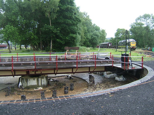 The 60-foot turntable at Rowsley during installation. This Cowans Sheldon Co. Ltd turntable (O/N 6181 5-Mar-1937) was originally supplied to Mold Junction M.P.D.
There's a little more information on the Peak Rail website here.
The re-commissioned turntable at Peak Rail was inaugurated by Pete Waterman on 1st May 2010, as described here.
 With Pete Waterman at the regulator, 8624 slowly reverses off the turntable (Photo: Sheila Rayson).
There is a collection of my pictures showing the Rowsley turntable in detail here.
Wolsztyn, Poland
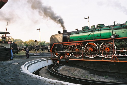 'Piekna Helena' on the turntable at Wolsztyn.
There's a brief description of my visit here and my pictures are here.
Kolomia, Ukraine
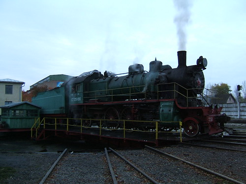 Su 251-86 on the turntable at Kolomiya.
There's an introduction to my trip to Ukraine, with links to other posts and pictures here.
Kiev, Ukraine
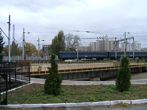 A large turntable in Kiev serving an 8-stall roundhouse and the works. Note the overhead catenary.
There's an introduction to my trip to Ukraine, with links to other posts and pictures here.
Mahlwagon, Yangon, Myanmar
 Mahlwagon Diesel Shed Turntable: 120 ton capacity metre gauge Mundt turntable built by Ransomes and Rapier in 1946.
There's a description of my visit to Mahlwagon Diesel Locomotive Shed here and my pictures showing the turntable at Mahlwagon are here.
A Model Turntable
 A model turntable in 4mm/foot scale.
There are more details of this model railway here.
There's an article on Wikipedia about railway turntables here.
[Link to 'The Oscillating Cylinder Engine' added 25-Oct-2015]
In the post 'Planet' at MOSI - The First 21 Years, I celebrated the 21st Birthday of the 'Planet' replica in October 2013.
When I was driving the 'Planet' replica, people sometimes asked if it was different from driving 'modern' steam locomotives. The answer is "not very, apart from the the fact she's a 'single wheeler', has a rather special braking system and an unusual method of reversing" ('Planet', like its immediate predecessor 'Rocket' has Slip Eccentric reversing). The basic principles of the steam locomotive haven't changed very much since the early days, although the appearance of the 'Planet' replica is very different from modern steam locomotives.

The 'Planet' replica being prepared for service with MOSI volunteer
Bev on the right.
I've already written about driving another early locomotive design in the post Driving 'Lion'. 'Lion' was built just eight years after the original 'Planet' and so there are many similarities, although 'Lion' incorporates Gab motion for reversing.
Adhesion
'Planet' has just one pair of driving wheels, which share the total weight of the locomotive with the leading pair of carrying wheels. Using Whyte's Notation, the arrangement is said to be a '2-2-0'. The total weight on the driving wheels is the 'adhesive weight'. With a single driving axle, not all of the locomotive weight can be adhesive. In the case of the original 'Planet' there was about 5 tons on the driving wheels, with about 3 tons on the carrying wheels. When the driver wants to get the train in motion, steam is used to generate sufficient torque at the driving wheels to move the load. But, if the torque applied to the driven wheels exceeds a critical value (related to the coefficient of friction between the wheels and the rails), the driving wheels slip on the rails and the train does not move.
This was more of a problem with goods trains, which tended to be heavier, so it was desirable to make all the locomotive weight adhesive to reduce the risk of slipping. On goods engines (then called 'luggage engines') the torque generated on the two driving wheels was shared with a similar pair of wheels linked to the driving wheels with coupling rods, giving a wheel arrangement of '0-4-0'. As the size and weight of locomotives increased, further coupled wheels were often used, although 'single-wheelers' weren't eliminated for some years as they could be free-running and, with large driving wheels, fast.
Because the 'Planet' replica only has one pair of driving wheels, it can be 'light on its feet' and prone to slipping so the driver has to take care when starting not to open the regulator too far.
Braking
In the early days of steam locomotives, effort was concentrated on making machines powerful enough to pull a useful load and braking technology was rather neglected. On both the original 'Planet' and the replica, there are two hand brakes, one on each side of the tender, and these are applied by 'screwing down' the handles which project from the top of the tender. Wooden brake blocks are provided which rub against the tyres of the tender wheels to provide braking. On the original 'Planet' that was it! This arrangement wasn't terribly effective in 1830 (severe braking could set the brake blocks on fire!) and, in the replica, the hand brakes are normally used only as a 'parking brake'.
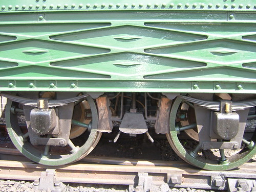
 Left side of replica tender showing the cast decorated panel and wooden brake blocks which are pulled against the tyres of the tender wheels by the screw handbrake to provide braking. Brake discs and calipers for the modern air brakes are visible between the wheel spokes.
To be acceptable for hauling passenger trains today, the 'Planet' replica also has an Air Brake system. This operates a disc brake on the leading axle of the locomotive, disc brakes on both tender axles and the train brakes. The regulator should always be closed before attempting to brake. I talk a bit about braking and the use of the automatic Vacuum Brake here. Air Brakes form another type of automatic braking (which I've not, to date, described). With the withdrawal of steam traction in the U.K., British Railways started to change over from vacuum braking to air braking and the 'Planet' replica has a version of what became the standard British Railways Two-Pipe Air Braking system.
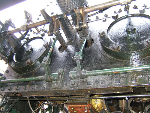
Converting steam into rotary motion
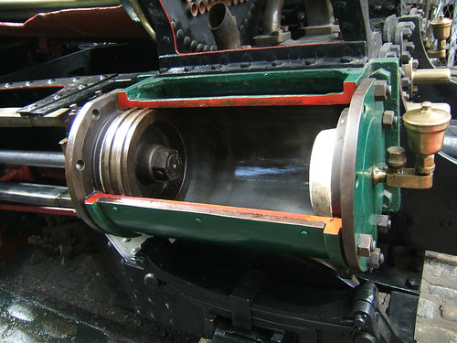
This part of the locomotive has changed little since the early days. The 'Planet' had two horizontal cylinders at the front between the frames. When the regulator is at least partly open, steam flows through the main steam pipe to feed the two cylinders. The principle is simple - the steam under pressure is used to push a piston to the far end of a steam-tight cylinder. The picture below shows a deliberately 'sectioned' cylinder making the construction clearer. The piston is attached to a Piston Rod which sticks out of one end of the cylinder (through a steam-tight piston gland) and it's the motion of the piston rod which allows the cylinder to do useful work.
 'Sectioned' cylinder on Beyer Peacock locomotive 'Pender' on display at MOSI. The piston is shown in its rearmost position in the cylinder and the Piston Rod extends to the left.
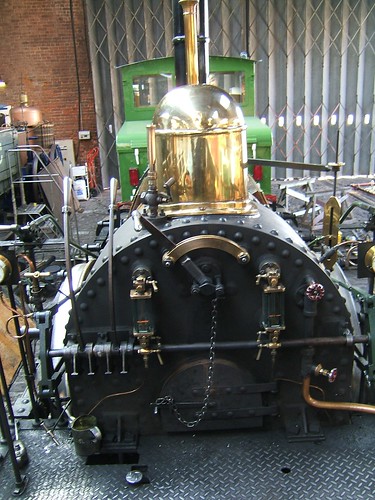
As the piston approaches the end of the cylinder, it's necessary to cut off the supply of steam and divert the steam to the other end of the cylinder so as to push the piston back again. This requires a valve in between the steam supply and the cylinder called (logically enough) the Steam Valve. The opening and closing of this valve must be synchronised with the movement of the piston. The two pictures below of the 'Planet' replica give an idea this was engineered in 1830, using complicated iron castings which were at the limit of what was technically possible.
The first picture below is taken inside the smokebox of the 'Planet' replica looking down onto the top of the left hand cylinder with the steam chest removed from the threaded mounting studs so as to show the flat port face area with two rectangular steam ports (connected to each end of the cylinder) and the larger rectangular exhaust port (connected through a passage to the blast pipe).

Top view of cylinder showing the cylinder ports (2 steam, 1 exhaust).
The second picture shows the underside of the steam chest which has been removed in the first picture. The steam chest is complete with the cast rectangular steam valve attached to the valve rod which sticks out of one end of the steam chest (through a steam-tight valve gland). The flat face of the valve bears slides to and fro against the flat port face so this type of valve is called a Slide Valve.
 Steam chest complete with slide valve and valve rod.
The reciprocating motion of the two piston rods is converted to rotary motion of the driving axle by connecting rods linking the end of the pistons which pull and push a double-crank driving axle, as shown in the picture below. Practical locomotives have at least two cylinders and, on a 2-cylinder design, the cranks are set 90 degrees apart so that both cylinders cannot be on dead centre. This means that a locomotive can always be started (using the effort from at least one cylinder), whatever the position of the cranks.
More than a century after the building of the original 'Planet', similar arrangements remained in use. An increasingly common variation was to move the cylinders outside the frames where the connecting rods drove onto crankpins fitted to the driving wheels, but both inside cylinder and outside cylinder designs lasted until the end of steam. Some designs had additional cylinders and a locomotive might have both inside and outside cylinders. As locomotives became larger, slide valves were replaced by balanced slide valves and then piston valves. A variety of other valves (poppet, sleeve) were tried but piston valves emerged as the most practical form of valve. A few attempts were made using quite different techniques, like steam turbines, but double-acting reciprocating cylinder designs remained virtually unchallenged.
Valve Gear
As remarked above, the opening and closing of the steam valve to admit steam from the boiler to either end of the cylinder must be synchronised with the movement of the piston. Since the piston is used to turn the driving axle, if the motion of the steam valve is derived from the turning of the driving axle, the necessary synchronisation is obtained. The motion of the steam valve is derived from the rotation of the driving axle on this design by a special eccentric. A simple eccentric is a type of crank with a small 'throw' - see Wikipedia here. A simple eccentric is fixed to the axle which turns it so as to produce the correct valve events to rotate the driving axle in one direction.
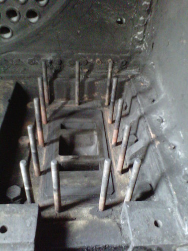
But a locomotive must be able to move in both directions and this was achieved in 'Planet' and other early locomotives by the use of a Slip Eccentric for each cylinder mounted in the middle of the crank axle, as shown in the picture below. A Slip Eccentric is an eccentric which can engage with the crankshaft in two positions where one provides the correct movements of the eccentric rod and the valve rod for clockwise rotation of the driving axle whilst the other position produces anticlockwise rotation of the driving axle. This is achieved by providing lugs or 'dogs' which can engage with one of two mating recesses or pits. A transverse shaft operated from a foot pedal on the footplate is used slide each eccentric across the axle so as to disengage one lug and allow the other lug to engage when the axle has turned so as to bring the other recess in line.
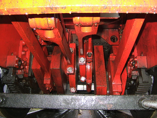
 "Planet's" driving axle and eccentrics viewed from below. L-R: RH driving wheel, intermediate axlebox, RH crank driven by (black) connecting rod, inside axlebox, RH eccentric and rod, LH eccentric and rod, inside axlebox, LH crank driven by (black) connecting rod.
Click here for a larger view
So, reversing the locomotive involves disengaging one lug in the slip eccentrics and turning the driving axle until the other lug engages. Achieving this probably provides the biggest challenge to the driver. There are two ways of achieving this changeover:-
1. Turn the driving axle by controlling the valves manually.
2. Perform a 'flying reverse'.
Reversing by controlling the valves manually involves operating the foot pedal to the other position, disengaging both valves from the eccentric rods (by operating the two small valve locking levers mounted on top of the left and right footplate railing) and operating the valves appropriately by hand (using the two curved levers mounted on the boiler backhead facing the driver) so as to move the locomotive. When the eccentrics have re-engaged, the two small valve locking levers are used to re-connect the eccentric rods with the valves, allowing the locomotive to be driven normally.
The 'flying reverse' is potentially simpler but requires careful judgment. This can be used if the locomotive is already in motion in one direction and requires to stop and then re-start in the opposite direction. The driver closes the regulator and uses the brakes so as to stop in the correct position. Before actually stopping, the foot pedal is operated to the other position. If judged correctly, the slip eccentrics will engage for the opposite direction before the locomotive comes to a stand. The 'flying reverse' can also be used if the locomotive is stationary but on a sufficient gradient so that it will roll when the brakes are released.
The view below of the footplate of the 'Planet' replica, shows the location of the controls used by the driver when reversing.

The 'Planet' replica in the Power Hall at MOSI. L-R: Steam chest pressure gauge, valve locking lever (on top of railing), two long curved levers (for manual operation of valves), foot pedal (for reversing), water gauge, regulator, water gauge, blower valve with injector steam cock below, boiler pressure gauge, valve locking lever (on top of railing).
Click here for a larger view
The two valve locking levers and the two long curved levers for the manual operation of the valves connect to the front of the locomotive via a series of rods. The picture below shows the two rocking shafts (top of picture) which operate the valve spindles controlling the valves in the steam chests described above. When the small valve locking levers are engaged, each rocking shaft is driven by the associated eccentric rod. To allow manual operation of the valves, the small valve locking levers disengage the eccentric rods from the rocking shafts by two shafts operating lifting links (near the bottom of the picture, painted green) which disengage each eccentric rod from its valve spindle.
 Looking at the front of the cylinders from underneath the locomotive showing the method of disengaging the valves from the eccentric rods. The cylinder front covers are dummy, made to the diameter of the original 'Planet'. The replica 'Planet' has smaller cylinders because of the increased working pressure (100 p.s.i. compared with 50 p.s.i. in the original).
Click here for a larger view
Development of Valve Gear
Slip eccentric reversing of locomotives did not survive. By providing four fixed eccentrics and eccentric rods, rather than two, the correct valve movements for both directions of movements on two cylinders could be provided. Initially, a mechanism connected to a simple reversing lever on the footplate connected two of the four eccentric rods to the valve spindles. For instance, 'Lion' of 1838 features Gab motion.
But, by 1842, Stephenson's link motion appeared in the U.K. offering not only reversing but variable cut-off allowing steam to be used expansively for greater efficiency. This became the predominant valve gear in the U.K. for many years. Don Ashton's authoritative review of Stephenson Link Motion can be found here,
For comparison with the picture above showing "Planet's" driving axle and eccentrics, the picture below shows "Sapper's" driving axle and eccentrics. "Sapper" is an 0-6-0 'Austerity' tank built more than a century after the original "Planet". Stephenson Link Motion had replaced slip eccentric reversing but otherwise the layout is similar.
 "Sapper's" driving axle and eccentrics viewed from below. L-R: RH axlebox and underhung laminated spring, RH crank driven by (red) connecting rod, RH fore eccentric and rod, RH back eccentric and rod, LH back eccentric and rod, LH fore eccentric and rod, LH crank driven by (red) connecting rod, LH axlebox and underhung laminated spring.
Click here for a larger view
Design issues
In general, materials and manufacturing techniques now are far superior to anything available in 1830. Steel was not available then - wrought iron was the best material but quality was very variable and only limited size sheets were available which required joining by riveting. Cast iron in the complex forms required for cylinders and valve chests was pushing at the limits of the technology available at the time.
The 'Planet' replica incorporates a number of features which were not possible in 1830 (for instance, air brakes, blower, injector, whistle, water gauges, pressure gauges) but that discussion I'll defer to a later article.
Related posts on this website
Early Locomotive Design.
The Planet Replica.
If your interest is broader than just the 'Planet' replica, there's a series of articles describing working on preserved railways and driving various steam locomotives. Most of these articles can be found here
My Pictures of the 'Planet' replica
'Planet'.
Arriving in Euston rather early for a meeting near London Bridge on Friday 21st August 2015, I decided on a quick 'whizz' looking at former Southern Railway stations. I descended into Euston Underground station and took the London Underground Northern Line (Charing Cross Branch) to Charing Cross.
At Charing Cross Station the impressive building facing the road provided by the South Eastern & Chatham Railway (SE&CR) has been retained and still has its hotel (now called the AMBA HOTEL CHARING CROSS). The original, fairly modest, concourse enjoying good natural lighting also remains but redevelopment has made the platforms themselves subterranean in appearance, illuminated by elaborate but rather dated looking lighting.
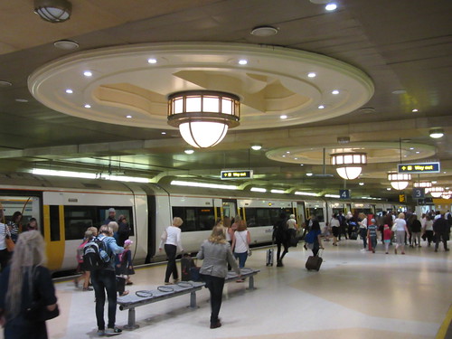 Platforms 3 and 4 at Charing Cross.
I realised that Southeastern trains do not currently stop at London Bridge, which is currently the focus of major works under the title Thameslink Programme, so I boarded the first departure and travelled just one stop to Waterloo East to see what's there now.
Immediately before arriving at Waterloo East, there's a good view of Waterloo terminal station next door. The elegant facade of the station contrasts oddly with the extended graffiti on the viaduct carrying the Charing Cross route.
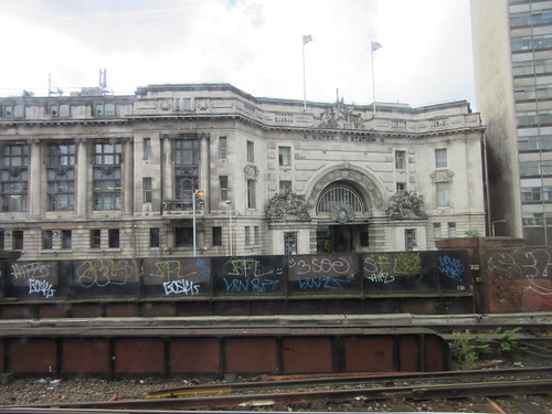 Waterloo station: The elegant facade of the station contrasts oddly with the extended graffiti on the viaduct carrying the Charing Cross route.
Waterloo East is a quite attractive station on the quadruple track route (paired by use) from Charing Cross to London Bridge. There is one island platform and two flanking platforms, all identified alphabetically as A - D, presumably to avoid confusion with its rather larger sister, Waterloo, to which it is connected by a footbridge at the Charing Cross end of the platforms. The early platform awnings and buildings survive, in a good state of restoration. I found the multi-coloured brickwork, simple detailing and cast iron, decorated columns quite pleasing.
Of course, many of the modern features jar. At some stage, the footbridge has been enclosed with the top pierced by a series of rather mean-sized windows. To accommodate all the electrical, signalling and communication requirements of today's railway, the buildings have been adorned with surface-mounted cable trunking. At the London Bridge end of the station, a subway interconnects the platforms and gives access to Southwark Underground station on the Jubilee Line. Needless to say, the interconnection to the Jubilee Line is in 'modernist' style, indifferent to the earlier station features with which it is juxtaposed. Modern platform awnings have been provided to cover what was formerly the exposed ends of the platforms - a useful feature but materials, treatment and even the roof height differ from the original.
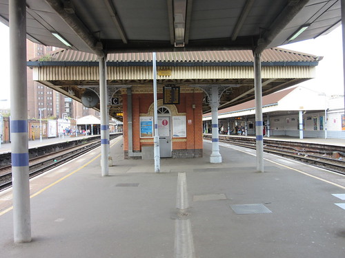 Waterloo East station: looking towards Charing Cross.
I took the footbridge to Waterloo main station where the pedestrian route emerges at the Waterloo Balcony Level. Escalators connect the Balcony with the concourse level and the platforms. I've written a little about the terminus at Waterloo in the post Waterloo Station, London. I took the opportunity to take a picture of the famous 4-sided clock.
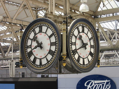 Waterloo station: Detail of the famous clock suspended above the concourse.
The short-lived and expensive platforms of Waterloo International (which were used by 'Eurostar' trains before HS1 and St. Pancras International were opened) have been brought into use again for domestic services, but I hadn't time to check out this area, instead descending the escalator to Waterloo underground station and catching a Jubilee Line service to London Bridge.
I walked to my meeting at a building near the moored H.M.S. Belfast, which I visited in 2012 as described here. With business concluded, I returned to London Bridge station. In order to have a closer look at the rebuilding in progress, I decided to catch a train from London Bridge to Cannon Street.
Until the Thameslink Programme started, London Bridge had six through platforms serving the SE&CR lines from the termini at Charing Cross and Cannon Street. The remainder of the platforms used by the Lodon Brighton & South Coast Railway (LB&SCR) were terminal, covered by an airy, glazed all-over roof comprising a central arched roof flanked by a series of glazed bays on either side.
 London Bridge in 2010 showing the terminal platforms with their all-over roof. The egregious 'Shard' starts its inexorable rise in the background.
All this has changed. On my visit, there were three through platforms serving the Cannon Street lines. The other through platforms have gone, replaced by two temporary through lines allowing Charing Cross services to run through without stopping. Six terminal platforms remain in use, connected to a large, new concourse area abutting the base of the Shard (the European Union's tallest building according to the Wikipedia article here. Later, at the beginning of 2017, I made a visit to 'The View from the Shard', described here, which gives excellent views of the railways around London Bridge).
It was only after my visit that I found the Network Rail description of the London Bridge project here and a Station Guide showing what's currently in use here.
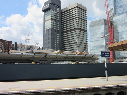 London Bridge in August 2015. View from platform 2 showing the grey hoarding dividing off the worksite, where two men can be seen working on new platform roofing. Red construction crane on the right and the base of the Shard.
I boarded a Cannon Street service but we'd only moved a short distance before suffering a signal check. Then, we slowly crossed the River Thames and arrived at Cannon Street station. The station retains its elegant twin towers but they are made to look faintly ridiculous by the appearance of the commercial development which has replaced the all-over roof, condemning yet another set of station platforms to a twilight existence.
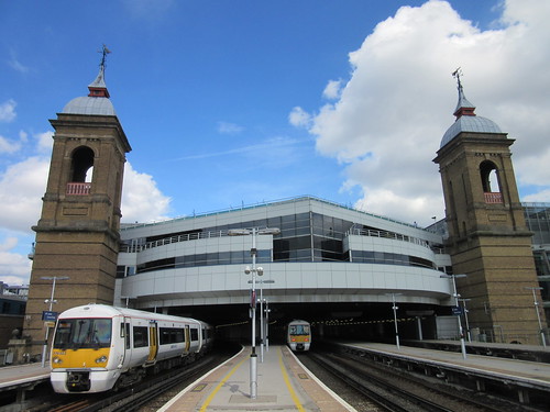 London Cannon Street Station.
I descended to the Underground at Cannon Street - this time to the District and Circle Line forming part of the 'Sub-Surface Line' network built using cut-and-cover techniques. The westbound train I caught was one of the fairly new 'S stock' sets built by Bombardier. They have similarities with the Bombardier sets for the London Overground featuring wide, walk-through access from coach to coach. I think they appear in seven- and eight-coach variants, with different seating plans. The set I travelled in had seating set against the sides allowing more space for standing passengers.
 District & Circle Line: Bombardier 'S' stock.
I changed trains at Embankment, catching a Northern Line train back to Euston where I boarded a Virgin service to Birmingham. Another train and a bus concluded my travelling for the day.
My pictures
London Charing Cross Station.
London: Waterloo Station.
London Bridge Station.
London Cannon Street Station.
[Link to post about visiting the Shard added 10-Apr-2017]
 Click here for larger view.
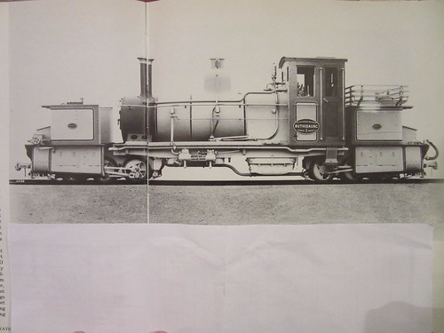
0-6-0+0-6-0 Garratt locomotive 'Buthidaung' No. 1 of the Buthidaw-Maungdaw Tramway Company Ltd. built Beyer Peacock, maker's number 5702 of 1913 (Photo: Beyer Peacock).
In Part 3 of Hugh Hughes invaluable guide to railway locomotives in India (introduced here), there is a brief description of the long-gone Arakan Light Railway in Burma (Myanmar), from which this account is derived.
The Arakan Flotilla Company founded the Buthidaung - Maungdaw Tramway Company in March 1913, to construct a 2ft 6in (762 mm) narrow gauge railway between these towns to improve communications in the remote area near Burma's border with what is now Bangladesh.
The consultant was Everard Richard Calthrop (1857-1927) who had worked for Robert Stephenson, the L&NWR, the GWR and the Great India Peninsula Railway before ill health forced his return to England in 1892 where he established a consulting practice.
In 1895 he was Consulting Engineer to the Barsi Light Railway in India (see the Wikipedia article here) where he was able to implement his ideas for effective narrow gauge railways - a combination of 2ft 6in gauge laid with 30 pounds per yard rail and an axleload of 5 Imperial tons on all axles. This proved very successful and his formula was adopted widely, including on the Arakan Light Railway and on the Leek and Manifold Light Railway in the U.K.
There's more information about the man in Grace's Guide here and Wikipedia here.

According to an illustrated booklet published in 1914:-
"The chief object of the tramway is to cater for the enormous inflow of coolies who yearly emigrate from Chittagong into Arakan for the rice harvest and work in connection with the rice mills, and also for the ploughing of the fields and the sowing an transporting of the crop. Many of these coolies travel on foot by overland tracks which converge near Maungdaw and diverge again at Buthidaung, and the Arakan Flotilla's launches bring a large number from Ucha Ghat at the head of the Naaf river down to Maungdaw. When the tramway is built, through tickets will be available right down to Akyab, by tramway and launch. As soon as the present line is in working order, further extensions towards the crowded districts of Chittagong and the roadless tracks of Arakan will be undertaken."
This enthusiasm was not shared by the public and in October 1916 Martin & Company of Calcutta registered the Arakan Light Railway Company in order to purchase and complete the line, with support from the Governments of India and Burma and the Arakan Flotilla Company. To cross the Mayu Range, two tunnels and gradients as severe as 1 in 33 were required. The line was just over 18 miles long.
The railway opened on 15th February 1919 but receipts were disappointing and covered only half the expenses, resulting in liquidation and sale to the Indian Government for dismantling.
The line had three locomotives whose fate is not known:-
0-6-0 saddle tank with 21.5 in. dia. coupled wheels and cylinders 7 in. x 12 in. built by W. G. Bagnall, maker's number 1900 of 1912 'Muriel' (no running number).
0-6-0+0-6-0 Garratt with 24 in. dia. coupled wheels and cylinders (4) 8.5 in. x 12 in. built by Beyer Peacock, maker's number 5702 of 1913 'Buthidaung' (running number 1).
0-6-0+0-6-0 Garratt with 24 in. dia. coupled wheels and cylinders (4) 8.5 in. x 12 in. built by Beyer Peacock, maker's number 5703 of 1913 'Maungdaw' (running number 2).
To meet the requirements of a tramway, the four sets of motion were enclosed - possibly the only Garratts so enclosed. They were arranged for left-hand drive and were provided with a vacuum ejector for train braking.There were three water tanks:-
280 gallons (smokebox end)
110 gallons (firebox end)
160 gallons (under boiler).
These two Garratts were the smallest ever built by Beyer Peacock.
Every year, the Old Locomotive Committee (OLCO) organises a get-together, called 'Lionsmeet' for modellers of the 'Lion' locomotive (and similar models of designs from the early days of railways). On Saturday 8th August 2015, 'Lionsmeet' returned to the home of Guildford Model Engineering Society (GMES) at Stoke Park, Guildford.
Getting there
I travelled by train to Guildford and there's a brief write-up at By Rail to Guildford.
The Event
My train took me to 'London Road (Guildford)' station, from where I walked along London Road to Stoke Park and signed in as a visitor at the GMES entrance. For more details of GMES, go to their website here.
The Steaming Bays are always the centre of activities and I found a number of our members there, together with John Brandrick (Chairman), Jon Swindlehurst (Treasurer & Membership Secretary), John Hawley (Magazine Editor) and Andrew Neish (Lionsmeet Organiser).
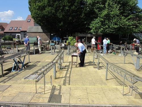 The Steaming Bays at Guildford M.E.S., with John Brandrick and Andrew Neish talking at the table in the centre of the picture. The lifting trusses in the foreground allow models to be conveniently transferred directly to and from parked vehicles.
Guildford is the 'home club' for both Andrew and his father David and together they were steaming David's reliable 'Lion' model. Jon Swindlehurst steamed his very successful 'Lion' and other 'Lion' models were also being prepared for service.
John Hawley kindly took me to the Clubhouse for a welcome cup of tea. The Clubhouse detained me for a while, because an interesting display of models had been arranged. My eye was taken by a handsome 0-4-0 tank locomotive named 'Cynthia'. Published as a 5 inch gauge design, "Gemma" was serialised in "Engineering in Miniature" magazine as a model of the Great Eastern Railway 0-4-0 built by Neilson & Company in 1874 (incidentally, there's a little about Neilson's in my post North British Locomotive Company Limited).
 The label on this striking model read: "Gemma built as the drawings came out in Engineering in Miniature c1983. She has had a hard life and can pull 3 adults with the blower full on. Living in the Gunnislake area in Cornwall at the time she is in the East Cornwall Minerals Railway livery. Our garden railway reflecting the full size a mile away. David and Lily Scott Reading."
There was a live-steam model of 'Invicta' from the Canterbury and Whitstable Railway. Mention of the Canterbury and Whitstable always reminds me of my favourite dialogue from the film 'The Titfield Thunderbolt' which I quote in my eponymous post here.
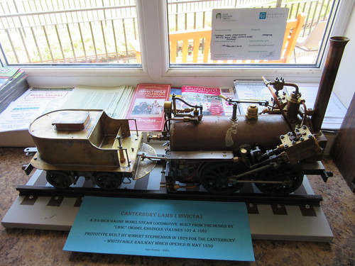 "Canterbury Lamb (Invicta) a 3.5 inch steam locomotive built from the design by 'LBSC' (Model Engineer Volumes 107 & 108). Prototype built by Robert Stephenson in 1829 for the Canterbury-Whitstable Railway which opened in May 1830. Peter Christmas - GMES."
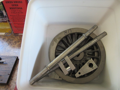
 Work in progress: Wheels and (far left) chassis: "Will be 'Royal George' by Timothy Hackworth 1827. No 'real' plans survive - so half the battle is to produce the 'engineering drawings'".
 Work in progress: Foreground: "5 in Gauge Lion under construction. Owner - John Hawley. Built to this stage by Michael Lee, loco and tender chassis completed. Running gear started. Boiler by Blackgates. All to LBSC design." Background: "Boiler for 7.25 in gauge Lion. Designed: John Hawley (OLCO). Built: Peter Carr (Kingswood Boilers)."
It was good to see that John Hawley is producing what he calls "Lionswarf" and is modelling, as well as editing.
 "A few of the components required to construct the leading and crank axle/wheel assemblies. I'm experimenting with round keys and semi circular keyways." - John Hawley.
In addition, one end of the Clubhouse housed a large well-detailed 4mm scale layout based on the long-gone G.W.R. terminus 'Cheltenham Spa St. James'.
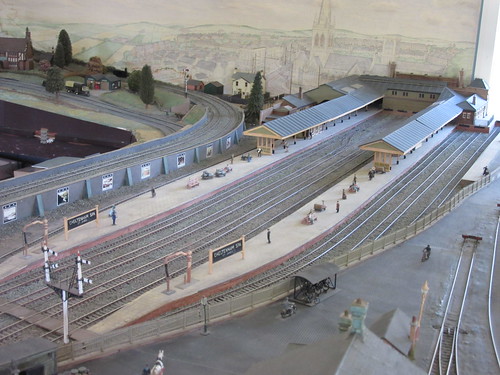 A view of part of the 4mm scale layout.
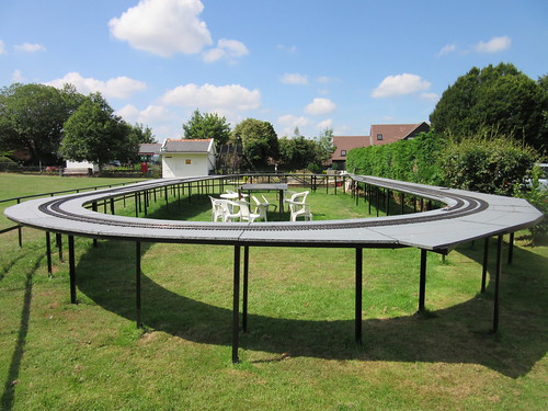
Fortified by a cup of tea, I found the Safety Officer, was kitted out with a High-Visibility jacket and then allowed to survey the running lines on foot. There are two 'deformed oval' running lines.
The inner circuit is an elevated dual-gauge track which features clockwise running. Colour light signals are provided. These operate automatically from short track-circuited sections in appropriate positions. The outer circuit is ground level 7.25" gauge with anti-clockwise running. This circuit also has signalling but the signal heads (which are removed after a running day for security) were not needed for 'Lionsmeet'. Part of this circuit is dual-gauge 5"/7.25", giving rise to some impressive dual-gauge pointwork. The ground level track has an attractive brick-built carriage and locomotive shed. A spur, complete with a number of semaphore ground disc signals built in 'Southern Railway' style leads to a turntable. This is a mature site and the extensive steaming bays with the large traverser are substantial and well-engineered.
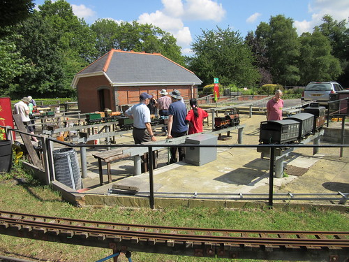 Lionsmeet 2015: Looking across the steaming bays towards the Carriage Shed.
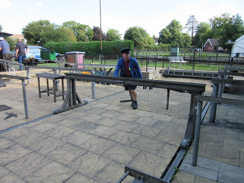 Andrew Neish moving the impressive Traverser in the Steaming Bays.
The steaming bays featured a 'Locomotion' model, lifted clear of the rails, operating on compressed air. A fascinating sight! There's a video clip on YouTube here. When you've watched the video, use the 'Back Button' to return to this post.
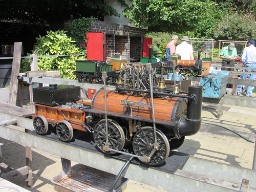 'Locomotion', lifted off the rails, was running on compressed air.
There are two other layouts offering live-steam running. The first is a well-established 32mm gauge fully landscaped layout intended for narrow gauge models.
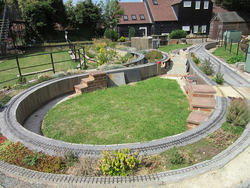 The 32mm gauge landscaped 'narrow gauge' circuit.
The second is a more-recent Gauge 1 layout featuring a double-track oval with sidings. This is built on a raised baseboard.
 Gauge 1 elevated layout under construction.
Various models of 'Lion' were steamed during the day. Sometimes the driver would be alone, sometimes one or more passengers would be taken - informality is the style of 'Lionsmeet'. Occasionally, OLCO members without a 'Lion' model would be given the opportunity to drive. David Neish kindly allowed me to take a turn on his 'Lion'.
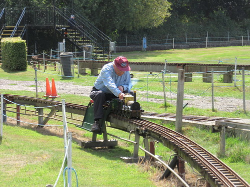 David Neish passing over the Sector Table which gives access to and from the Steaming Bays.
 'Lion' with a rather smart driving trailer passing over the Two-leaf Swing Bridge.
One performer was in the striking red and green livery from the film and carried 'Thunderbolt' nameplates.
 'Thunderbolt', in the striking livery from the film.
The host society had provided a splendid buffet lunch in the Clubhouse, so most railway activities ceased for a while, before resuming with added gusto. Later in the day, both John Brandrick and John Hawley had a drive.
 John Brandrick driving David Neish's 'Lion'.
 John Hawley at speed with Jon Swindlehurst's 'Lion'.
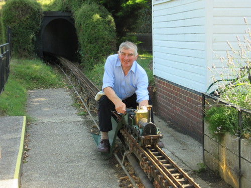
John Dalton from Chelmsford M.E.S. had brought his 7.25in gauge 'Lion'. I'd first seen this model at Kinver during 'Lionsmeet 2010 (there's a brief description here) but at Guildford, I managed to get a ride behind this engine.

John Dalton's 7.25in 'Lion' performed on the ground level circuit.
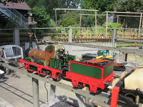
David Neish was determined to steam his Gauge 1 Aster 'Lion'. It was set up on the Gauge 1 layout and, with assistance from Roger Hayward, was successfully steamed. I found the management of these Methylated Spirits powered models most strange - no water gauge, no pressure gauge (but there is a safety valve). Although water can be added, this is done from a dispensing bottle against boiler pressure. Apparently, when it runs out of water, the absence of steam to the blower means that the boiler remains safe! After a bit of experimenting, 'Lion' successfully completed a lap and honour was satisfied. An OLCO member had brought his own Aster 'Lion' which he had never steamed and, with suitable ministrations from Roger Hayward, this, too, operated to the owner's delight.
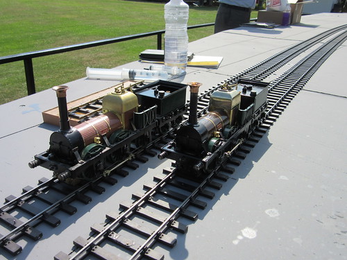 Two Gauge 1 Aster 'Lion' models.
At 'Lionsmeet' 2014, a new member surprised us by displaying an early 'Lion' model he'd acquired. Well, no, he didn't bring his locomotive and run it at Guildford. Instead, he surprised us by arriving in his veteran 'Alvis'.
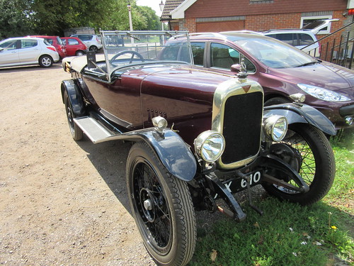 One OLCO member arrived in this veteran 'Alvis'.
We enjoyed wonderful weather and the Guildford Club had made us most welcome, so it was another successful 'Lionsmeet' and thanks are due to all concerned. As a tailpiece, I couldn't resist this picture of Roger Hayward's unusual live steam narrow gauge locomotive 'Nanny Bubbles' which he ran on the 32mm gauge track.
 Lionsmeet 2015: Roger Hayward's narrow gauge 0-4-4T 'single-ended Fairlie' 'Nanny Bubbles' on the 32mm gauge layout.
Lionsmeet pictures
Lionsmeet 2015.
[Video clip of 'Locomotion' model added 22-Aug-2015]

 Waterloo Station from the air (Photo: Network Rail).


