Thursday, 10 January 2013

Crewe North Junction (1940) Signal Box

A modern view of Crewe North Junction Signal Box, still in situ but now forming part of Crewe Heritage Centre and overshadowed by the overhead electrification structures.

Crewe North Junction Signal Box controlled movements at the North end of Crewe Station from 1940 to 1985. The signal box has been preserved in situ and now forms a major exhibit at Crewe Heritage Centre. This 'ARP' box, with two large Westinghouse Style 'L' Power Frames, is the last-but-one in a series of signal boxes which have controlled the important junctions at the north end of Crewe Station. There's a very brief history of these signal boxes here.

In 1938, with the threat of war and aerial attack looming, it was decided that certain strategic signal boxes should be replaced by an 'ARP' ('Air Raid Precautions') design, better able to withstand blast damage. Accordingly, Crewe North Junction signal box was rebuilt, replacing the earlier 1907 signal box which used the 'Crewe' All Electric System with electric operation of points and semaphore signals.

Westinghouse Brake and Signal Company had been supplying the Style 'L' miniature lever frame since 1929 so it was a 'safe' choice. The L.M.S. order for Crewe North Junction (together with a second for Crewe South Junction and a third 'Standby' frame) was placed in March 1939. The following month, further orders were placed for two more Style 'L' frames for the resignalling of Preston. The Preston project never went ahead and the equipment ended up being used at Euston after the Second World War! Finally, a further frame was ordered for Liverpool Lime Street in January 1940.

The Crewe North Junction lever frame order called for 214 levers made up of 65 point levers, 120 signal levers, 7 'special' levers, 12 spare levers and 10 spare spaces. These levers were divided between two lever frames mounted back-to-back, with a walkway in between to allow maintenance, on the first floor of of the building (the 'operating floor'). A series of windows allowed the signalmen to actually observe the trains they were controlling.
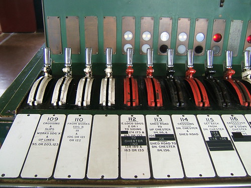
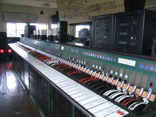
Detail showing miniature levers. White are spare, Red are signals, Black are points. The lamps on the almost vertical panel behind the levers are repeaters.

Movement of each lever drives a vertical shaft via bevel gears. The vertical shaft carries the electrical contacts used for control and interlocking.
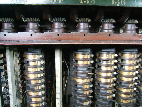
With covers removed, the bevel gears which drive the vertical 'drum' of contacts can be seen.

The associated relays which provide the electrical interlocking are mounted on steel shelves in a large Relay Room on the ground floor. 'Shelf' relays are used, interwired on site.
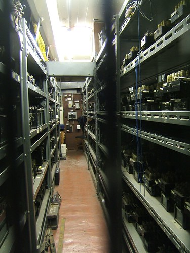
One aisle in the large Relay Room. Shelf-type relays (inter-wired on site) fill the metal shelving.

Looking at Crewe North Junction box from the platforms when I was young, I thought it looked mysterious, with its unfamilar architecture sitting out-of-reach across the maze of trackwork. Finally, I got to visit the box in the 1970s two or three times when my firm had started supplying telecommunication equipment to the railways.

In 1985 control of the Crewe area was transferred to an industrial building painted red and white looking more like a fugitive 'B&Q' than a Signalling Centre. I feared for the future of the redundant 1940 Crewe North Junction signal box but, remarkably, it has survived as part of Crewe Heritage Centre.

In December 2008, I returned to Crewe North Junction box, which is looked after by a group of ex-railwaymen and enthusiasts and I was invited to 'signal' a few moves on the Style 'L' Power Frame.

References

'The Style L Power Frame' written and published by J. D. Francis 1989 (ISBN 0 9514636 0 8).

External Links

Crewe North Junction signal Box (Wikipedia).
Crewe North Junction by Mark Adlington.

My Pictures

Crewe North Junction Signal Box.
Crewe Area.

Tuesday, 8 January 2013

Preparation of Locomotive 'Sapper'

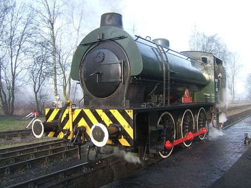
'Sapper' on the outside pit at Rowsley being prepared for the day's running.

In this post, I concentrate on the Driver's duties in oiling and examining the locomotive. Preparation of 'Sapper' is generally similar to preparation of other 'Austerity' tank locomotives, such as Peak Rail's 'Royal Pioneer' (currently posing as '68013') described a few years ago in the post here. The most noticeable difference in 'Sapper' is the use of two 'Wakefield' Mechanical Lubricators to ensure a reliable supply of oil to important parts of the locomotive.

The person oiling the locomotive should always carry a clean rag or woven 'Wiper' to remove any spilt or excess oil. Oil where it shouldn't be will become transferred to the next person to visit that area. In places like the foot framing, spilt oil is likely to be hazardous as it can cause slips. Any dust or ash around will tend to mix with the oil and produce an unsightly and hard to remove coating.

Mechanical Lubricator for Cylinder Oil
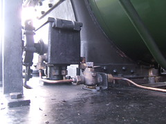
A 'Wakefield' Mechanical Lubricator for Compound Cylinder Oil ('Steam Oil') is mounted on the left foot-framing just behind the smokebox. The box-like casting (which is filled with the appropriate grade of clean oil daily or as necessary) has a hinged lid clamped shut to exclude dust and ash. Immersed in the oil are small oil pumps driven from a shaft which passes through a gland to the circular ratchet mechanism marked 'WAKEFIELD' visible in the picture above.
The ratchet mechanism is oscillated back and forth by suitable connections to a reciprocating or rotating part of the motion. In the case of 'Sapper', the Mechanical Lubricators are operated from small eccentric cranks mounted on the crankpins of the leading axle. As the mechanism is oscillated, an internal pawl rotates the shaft through a small angle on each oscillation. Thus, whenever the locomotive is in motion, the pumps are delivering oil through the elbows and copper oil lines visible on the left of the Lubricator. To make sure that the oil lines are 'primed' with oil before leaving the shed, the 'U' shaped bar connected to the shaft is manually rotated a number of times.

This view shows the 'Wakefield' Mechanical Lubricator viewed from the rear of the locomotive. Cylinder oil has quite a high viscosity (usually at least SAE 680) and it can become very viscous in cold weather. The copper pipe on the right is a steam feed to the cock mounted on the foot-framing just behind the lubricator. When the square-headed cock is unscrewed, steam is passed through a heating pipe to warm the oil.

Sight-Feed Lubricator for Cylinder Oil
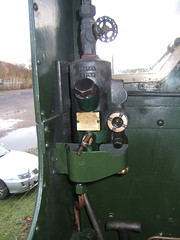
As built, 'Sapper' will have been provided with just a Sight Feed Lubricator. Where a Sight-Feed, or similar, lubricator is fitted, this is usually mounted on the fireman's side so that makes it more logical for the fireman to look after the 'steam' oil. 'Sapper' has a 'Eureka' Type 'G' single-feed sight-feed lubricator on the Fireman's side of the cab. As I've commented elsewhere, the Great Western Railway regarded sight-feed lubricators as so vital to the running of the engine that the lubricator was always fitted in front of the driver and was the drivers responsibility. To find out more about the G.W.R. approach see the post Summer Saturday with a '2884' and, in particular, the last section titled 'Sight Feed Lubricator'. Normally, once a mechanical lubricator is fitted to a locomotive, no sight feed lubricator would be provided but 'Sapper' has both types and both types are used.

Mechanical Lubricator for Axlebox Oil
A second 'Wakefield' Mechanical Lubricator for Axlebox Oil (often called 'Motion Oil') is mounted on the right foot-framing just behind the smokebox. Construction is similar to the Mechanical Lubricator for Cylinder Oil but the casting is larger to accommodate additional oil lines (in this case six, one per axlebox. In this case, the window showing the oil level faces outwards and can easily be checked during preparation (there is a check window on the Mechanical Lubricator for Cylinder Oil but it faces the centreline of the engine).

Oiling Round

Of course, checking the oil level in the Mechanical Lubricators and priming them is only one task. There are six oil cups on the coupling rods to be filled and two holes to place oil on the Gradient Pins.
There is an oil box on the framing either side behind the smokebox delivering oil to each piston gland and each valve gland. There are two oil boxes (left and right) on the frame stretcher which serves as a motion plate. Each oil box has four oil lines delivering oil to the front and rear of the upper slide bars associated with each cylinder. There are oil cups closed with corks on the two little ends and two more on the valve rods where they pass through the motion plate. I find I can best reach these last points by lying on the foot framing and reaching into the motion but each person has to find a method which suits their build, reach and fitness. On 'Sapper' there are also two oil boxes (left and right) fitted further back just above the frames. Each has three oil lines feeding oil to the hornguides. The right hand one is best reached from outside, but the left one I tend to defer until I'm between the frames, described next.

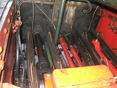
The next bit I find the hardest. Starting on the foot framing on the fireman's (left) side, I lower myself in between the frames behind the weighshaft and ahead of the crank axle, standing on the brake rigging facing the rear of the engine. How easy this is depends on the 'angle' that the motion is sitting at. In the picture, the right crank is near front dead centre and the left crank is near the top. With luck, the oil cups closed with corks on the two big ends and the four eccentrics can be dealt with, hopefully without dropping a cork into the pit.

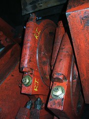
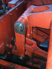
Then, I try to turn round so as to face the front of the engine. If the left hand crank is anywhere near the top, I usually end up sitting on the connecting rod. The picture shows the four lifting links suspended from the 'arms' on the weighshaft. Pairs of lifting links are attached to the left and right curved, slotted expansion links. The top of the each expansion link is connected to the associated foward eccentric rod, the bottom of each expansion link is attached to the associated reverse eccentric rod. The picture gives a fair idea of the rather poor access. There are a number of oil holes to be dealt with - at the top and bottom of the lifting links, at the top and bottom of the expansion links and on each dieblock (to provide lubrication to the machined faces of the curved slot in the expansion link). Those are the major oiling points but, as described in the earlier post, there are other points which may benefit from the judicious application of oil.

On locomotives fitted with a steam brake, there is usually a small oiler near the boiler backhead, positioned in the steam line to the steam brake cylinder. 'Sapper' has a cylindrical oiler, normally dealt with by the Fireman by filling it with Cylinder Oil during preparation. This oil is allowed to find its way to the brake cylinder, with the aim of avoiding a 'stuck piston'.

Examination
As important as careful attention to oiling is the 'Daily Exam'. Every part of the construction should be studied during preparation, looking for anything unexpected - something becoming detached, unusual wear, missing split pins or nuts, anything broken, loose or showing signs of cracking (particularly on the springing), anything out of alignment. Time spent in examination at this stage reduces the chance of embarrassment later due to a failure. A pit greatly assists a proper examination, allowing wheels, axleboxes, springs and spring hangers to be closely examined. The picture shows the view forward from just in front of the firebox. The connecting rods are left and right and the two reverse eccentric rods are in the middle, closest to the camera with the expansion links behind. The motion plate is in the background.

Photographs

Larger versions of all the pictures in this article (plus other pictures of the locomotive) can be found in the set below:-

'Sapper' Austerity Tank Locomotive

Thursday, 3 January 2013

A. F. Bound

A. F. Bound (Photo from 'A Pictorial Record of L.M.S. Signals, see reference 1 below).

Arthur Frank Bound was a pupil of Billington on the L.B.S.C. before working with the British Pneumatic Railway Signal Company. This led to an interest in modern signalling methods (and membership of the signal section of the American Railroad Association). In 1906 he was appointed Assistant Signal Superintendent and later Signal Superintendent of the Great Central Railway at Guide Bridge, Manchester.

An advert for the British Pneumatic Railway Signal Company which appeared in 'Power Railway Signalling' published 1908 (reference 2).

He became a Member of the fledgling Institution of Railway Signal Engineers in 1913. In 1915 he read his Paper 'A Review of the Art of Signalling, and some Suggestions' at the A.G.M. in February. This gave rise to Discussions firstly on the day, later in March and April with Bound's Reply in June. The initial paper, the Discussions and the Reply are available online here). By 1916 Bound had become a Member of the Council of the Institution.

In 1924, he was the LNER Signal Engineer (Southern Area) based at Liverpool street Station, London and he became Vice-President of the Institution of Railway Signal Engineers the same year. The following year, he served as President of the Institution.

The combination of progressive, incisive thinking with consideration towards his staff earned him great respect.

In 1929 he joined the LMS as Chief Signal & Telegraph Engineer. He embarked on a long-term program of risk reduction by converting semaphore Distants to colour light signals to reduce the chances of a 'missed distant'. Bound also prioritised the introduction of track circuits and block controls, dealing with the biggest risks and the more important lines first.

In 1932, he was responsible for the 'Speed Signalling' experimental installation at Mirfield. This is described on the splendid site called 'The Signal Box' site in an article here.

Bound introduced a number of power signalling schemes, associated with more conventional colour-light signals such as the 1940 renewals at Crewe. This is mentioned in my post Crewe North Junction History and there's a set of pictures of the now-preserved Crewe North Junction Box here.

One of the two miniature lever frames in the preserved Crewe North Junction box.

But Bound's influence extended to the more mundane, such as signal box nameboards. Bound had been impressed by the Great Central practice of fixing a nameboard at each end of the box rather than on the side facing the track - much easier to sight from a train. After some experimentation, the standard L.M.S. signal box nameboard appeared in 1935, using six inch cast letters fixed to a 9-inch high wooden board with a three-quarter inch rounded bead. For more details, see the reference below.

L.M.S. pattern nameboard applied to an L.N.W.R. signal box photographed at Brereton Sidings in 2007.

Over the years, A F. Bound left an indelible stamp on the signalling infrastructure of the L.M.S which survived long after he was succeeded by W. Wood in 1944.

Reference:

1. 'A Pictorial Record of L.M.S. Signals' by L. G. Warburton, published by Oxford Publishing Company in 1972 (available, for a price, on the second-hand market).
2. 'Power Railway Signalling' by H. Raynar Wilson published 1908. Reprinted in 3 parts by Peter Kay.

[Revised 4-Jan-2013]

Tuesday, 1 January 2013

Loco-profile No. 5: The Russian 'E' class 0-10-0

Lugansk works built the first 'E' class 0-10-0 locomotive in 1912 and, including later sub-classes, this became perhaps the most prolific design in the world. Despite numerous initiatives to move on from this design, the 'E' class remained remarkably resilient and I was able to drive two examples of the E' class (the 'Em' and 'Er') in 2005 when I went on a steam driving holiday which is briefly described here.

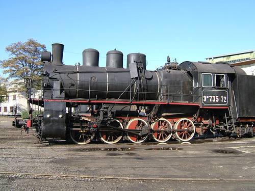
Em 735-72 at Kolomiya Depot, Ukraine.

Front view of Em 735-72 at Kolomiya Depot.

Note that the complete smokebox front is hinged on the right and, once unbolted, can be swung open for re-tubing and access to the tubeplate. There is a smaller door in the smokebox front used for char removal. This door is hinged on the right and secured by 14 'dogs' or clamps which, when tightened, ensure that the smokebox door is airtight.

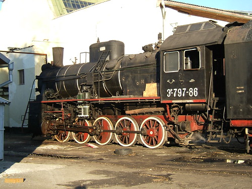
Er 797-86 at Kolomiya Depot, Ukraine.

For technical specifications, refer to Reference 1.

References:

Reference 1: 'Soviet Locomotive Types - The Union Legacy' by A J Heywood & I D C Button (Frank Stenvalls Forlag) ISBN 0-9525202-0-6.

Photographs:

Locomotive Profile: Russian 'E' class 0-10-0

Review of the Year - 2012

I find it hard to believe this is the seventh 'Annual Review' I've posted. Once again, I've been extremely lucky. Despite reaching "Three score years and Ten" (when the Manufacturer's Guarantee expires) I'm still fit enough to enjoy new experiences. Not being sure how long this situation will prevail, I managed to cram four overseas trips into the year and a fair bit of time on the footplate.

OVERSEAS TRAVEL

Safari

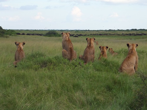
Seven lions watching a large herd of buffalo at Duba Plains, Botswana.

I thought I ought to 'go on safari' at least once in my life. I ended up visiting Zambia and the Victoria Falls, Namibia and a few days river cruising followed by a very luxurious trip with Wilderness Safaris in Botswana. Of course, I feel a little guilty that I didn't 'rough it' but it was exceptionally enjoyable. There are 28 posts describing the trip and these posts include links to my pictures.

Mongolia and the Trans-Siberian

The Circum-Baikal Railway winds along the edge of the huge Lake Baikal in Russia.

My planned trip to Tibet was cancelled at short notice because the Chinese stopped issuing tourist visas. Instead, I flew to Ulaan Bataar, witnessed the Mongolian annual National Games and then joined the 'Golden Eagle' private train back to Moscow. This adventure is described in 17 posts which include links to pictures.

Burma

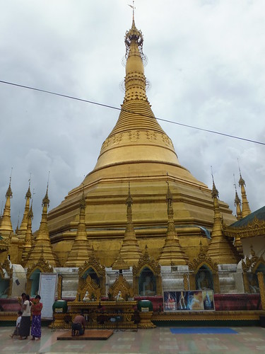
Kyaikthanian Paya Pagoda, Mawlamyine.

Once again, I returned to Myanmar which is now slowly starting to "come in from the cold" following visits from both the British Prime Minister and the American President. This time, I went south to Mawlamyine before taking the 'Road to Mandalay' river cruise to Bhamo. I also made visits to a number of schools and the medical clinic supported by the 'Road to Mandalay' Social Contribution. 21 posts describe the trip and give links to my pictures.

Malta

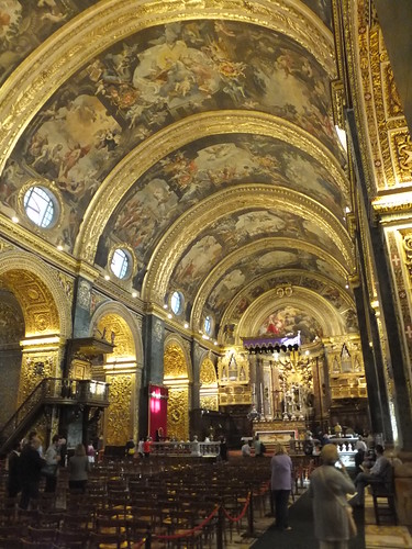
Saint John's Co-Cathedral, Valetta.

I accompanied Ann and Dean for a week in Malta. It had been many years (I'm not sure how many) since my previous trip and I was surprised at how much had changed. There are 8 posts which describe the trip and include links to my photographs.

RAILWAYS

Railways, General

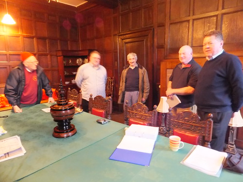
John, Phil, Mick, Ian and Mike at Brewood Hall.

A small group of enthusiasts met again at Brewood at the end of January 2012 (details). During the year, the group has exchanged information and queries during by e-mail.

Railways in the West Midlands are a particular group interest and that encouraged me to add a number of articles during the year including:-
Sedgeley Junction, Deepfields, Tipton, Tipton (again), Tipton Station Shunting Frame, Rail & Canal at Bloomfield, 'Breakdown' at Bloomfield, Albion, West Midland Railways.

Railways, U.K. Modern Image

I still use what remains of our national railway network for getting around but without much pleasure, I'm afraid. Occasionally, that provokes a post (usually some rant about the Train Operating Companies or the dreadful Network Rail), such as:- Liverpool by Train and London and Birmingham in 2012.

Railways in Zambia

During my safari holiday, I discovered that there's a railway museum in Livingstone which, of course, I visited giving rise to an article here with a link to a set of pictures.

Quite by chance, I was in Livingstone on one of the days when the steam-hauled Royal Livingstone Express dining train operated. I managed a footplate ride described here (with a link to my pictures). I also made a short post on Zambesi Sawmills Railways. Since many of the locomotives I'd seen in Zambia were North British Locomotive Company products, on my return to the U.K. I added the article North British Locomotive Company.

Railways in Mongolia and Russia

There was obviously a strong railway theme to my Mongolia and Trans-Siberian holiday and the 17 posts in the series Trans-Siberian include a fair bit of 'technical' content together with links to my railway pictures. In addition, there are a number of 'specialist' articles including:-
Russian Railways, Russian 'YeA' class, Mongolian Railways, Russian 'FDp20' class 2-8-4, Russian 'FD20' class 2-10-2, Numbering of Russian Locomotives and Rolling Stock.

Railways in Burma

During my trip to Burma described above, I used the railway from Yangon to Kyaikto, Katha to Naba and made another trip on Yangon's Circle Line. In addition, I made various brief visits to stations by road. There are a few new posts including:- Yangon to Kyaikto by Train, By Train to Naba, Bago to Kyaikto by Train, The Circle Line Revisited and the start of a series on 'Railway Signalling in Burma'.

PRESERVED RAILWAYS

I am currently Secretary of the Old Locomotive Committee and an active volunteer at MOSI, The Battlefield Line and Peak Rail.

The Old Locomotive Committee

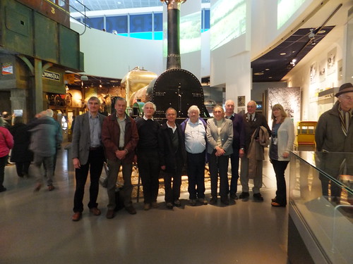
Members and Officials of OLCO in front of "Lion" after the 2012 A.G.M.

My first involvement in preservation was with the locomotive 'Lion' and the Old Locomotive Committee. Now 'Lion' is on display in Liverpool Museum, that chapter is closed, but I'm still Secretary of the Old Locomotive Committee which, in addition to its study role, encourages live-steam modellers of 'Lion', holding an annual competition for 'Lion' models called 'Lionsmeet'. I've added a few posts during the year including:- The Titfield Thunderbolt, Driving 'Lion', OLCO AGM 2012 and Lionsmeet 2012.

MOSI

MOSI (the Museum Of Science and Industry at Manchester) has now become part of the Science Museum Group. Steam train rides continue on the Museum's Demonstration Line using the 'Planet' replica and restored four-coupled saddletank 'Agecroft No. 1'. I've always loved the site, as the 1830 Goods Warehouse, Station Buildings, Irwell Bridge and other constructions comprise (albeit somewhat altered) the First Passenger Railway Station in the World. This is a marvellous legacy and to be able to take a steam train ride on the site, even today, represents a triumph of preservation. Of course, Network Rail have decided that a new line - the Ordsall Chord - is required to improve rail communication between Manchester's various stations so the steam operation at the Museum is currently threatened. Posts during the year include:- Agecroft at MOSI, MOSI Mini Maker Faire, Day out with Thomas at MOSI and Santa Specials - 2012.

The Battlefield Line

I did a number of 'turns' in the year, often on the diesel railcar (including a 'Midweek' on Wednesday 22nd August and 'DMU Shuttle' on Saturday 20th October 2012 as part of the 'Friendly Engines' weekend). Unfortunately, I was overseas for the Steam Gala. The railway had originally planned to hold more 'Day out with Thomas' days in October but these were cancelled. New posts during 2012 include:- 'Thomas' at the Battlefield Line, Battlefield Line Modellers' Weekend 2012, A Day on the Footplate (1), Battlefield Line 1940s Weekend (June 2012), A Busy Few Days and The Bear's Story. On 31st December 2012, I drove the diesel railcar on a 'Mince Pie Special' day. The weather was pretty foul for most of the day but the trains were fairly well patronised and everybody remained in good spirits.

Peak Rail

During 2012, the service has normally been top-and-tailed to Matlock Town, with a steam locomotive at the south end and and a diesel at the north end. We started and finished the year with 'Sapper' as the steam locomotive leaving '68013' to perform the balance of the running. The first main-line steam charter to Peak Rail for some years provided a milestone, as the train engine 'Oliver Cromwell' was turned for the return journey on the turntable at Rowsley. Once again, the 1940s Weekend proved very popular. A number of posts have been added during the year including:- Peak Rail in Winter, Steam Charter to Peak Rail, A Day on the Footplate (2), Peak Rail 1940s Weekend 2012, A Busy Few Days and Santa Specials - 2012.

BREWOOD HALL

I understand that rainfall in the area during 2012 was the heaviest since records began (about 100 years ago). It certainly seemed damp and clammy for much of the year. There were no major events in 2012 but a few posts have been added during the year including:- Railway Friends at Brewood (also referred to in 'Railways, General' above), The Brewood Buddha Statue, Oak Tree Pruning at Brewood Hall.

PREVIOUS ANNUAL REVIEWS

2011
2010
2009
2008
2007
2006

Saturday, 29 December 2012

Railway Signalling in Burma - Part 2: Colour Light Signals & Motor Points

The British built the extensive metre gauge railway network in Burma. I've not travelled widely on the railways in Burma, but I try to keep a look-out when in the country.

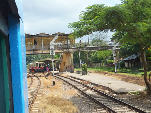
Colour light signals and power-operation of points are in use at Yangon Central Station and around Yangon's Circle Line. I've also seen colour light signals on a brief visit to Mandalay station.

Colour Light Running Signals

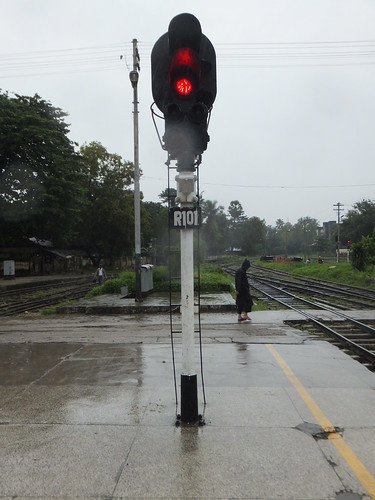
Signal 'R101' on Platform 3 at Yangon Central Station. A multi-LED lamp has replaced the original filament lamp.

Running signals are 2-aspect or 3-aspect, with some 'searchlight' types within Yangon Central Station. Position light subsidiary aspects are provided where necessary. In places, multi-LED lamps have replaced the original filamentary lamps.

Route Indicators

Following British practice, Route Signalling (rather than Speed Signalling) is in use. In general, routes are indicated by a 'Line of Lights' but there are a few Theatre-Type route indicators.

Rear view of two 3-aspect signals with 'Line of Lights' route indicators at Pazundaung.

2-aspect colour light signal with theatre route indicator on the Down platform at Pha Yar Lan. Note the two side lenses (sometimes called 'pigs ears' in the U.K.) for the benefit of a driver stopped at the signal.

Ground Signals

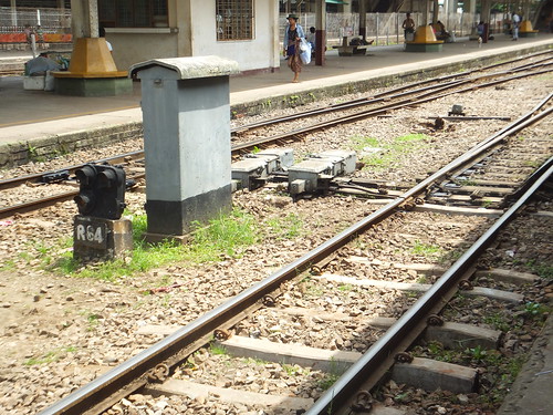
To control shunting movements, position light ground signals are provided.

Position light shunting signal R64, location case and two point machines in Yangon Central Station.

Point Operation

In colour-light areas, points are electrically-operated using point machines. One type of machine is shown in the picture above. The picture below shows another type of point machine at Pa Ywet Seit Gone.

Point machine at Pa Ywet Seit Gone.

Photographs

  Burma: Colour Light Signals & Motor Points.

The above set of pictures is part of a Collection Railways in Burma.

[Remarks on theatre-type route indicators clarified: 18-May-2016]

Friday, 28 December 2012

Railway Signalling in Burma - Part 1: Semaphore Signals

In the 19th century, Myanmar, then known as Burma, was administered as part of 'British India'. The British built the extensive metre gauge railway network so it’s not surprising that the signalling installed largely followed British practice.

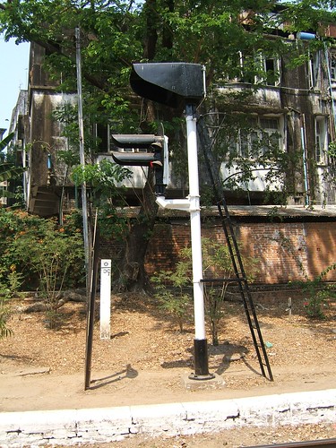
But the surviving semaphore signals are a very odd collection. I imagine that this is at least partly the result of Burma being cut-off from the West during the 50 years of military rule. What's visible now gives the strong impression of being cobbled-together on a 'make-do-and-mend' basis from whatever was available.

The British Legacy

I've not travelled widely on the railways in Burma, but I try to keep a look-out when in the country. The best example of a 'typically British' signal I've seen so far is at Bago.

A 'typically British' lattice-post bracket signal at Bago.

Although the stop signal arms are red with a white band on the front, a further embellishment is provided in Burma. There are two circular 'spots' in white, one on the left, the other on the right of the white stripe. A small square in the 'spots' reveals the red arm colour. It's hard to resist the conclusion that this elegant bracket signal was built in the U.K. and shipped out to Burma (although the mixture of upper-quadrant main arms and lower-quadrant subsidiary arms is puzzling).

Made in Burma

Elsewhere, signals show little standardisation as if each application was built from scratch with whatever was to hand.

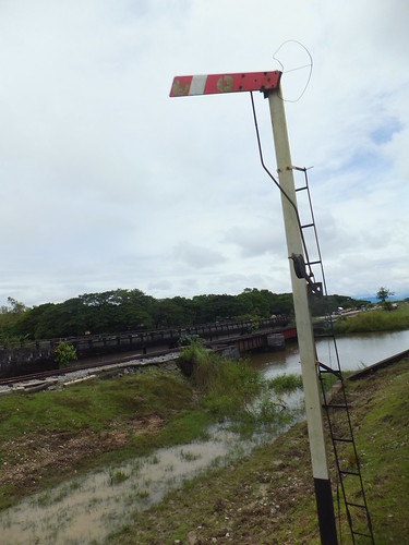
A curious stop signal in between Bago and Kyaikto.

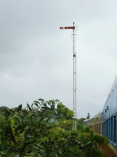
A fairly extreme example is shown above. First, the signal post appears to be a rolled section, probably 'T' profile. A pivot for the signal arm has been fitted right at the top of the post and there is no finial. The signal arm looks 'second-hand' and it carries the two 'spots' described above. It appears to be bolted to a casting which would normally include the 'spectacle' carrying coloured glasses allowing the signal to display a coloured indication at night. In this case, the casting has no spectacle but the shape of a typical lower-quadrant 2-aspect spectacle frame has been made out of steel rod. I can't see the function of this frame - the 'spectacle frame' is too thin to improve the signal sighting, no signal lighting is provided so there are no coloured glasses and it's certainly not aesthetically satisfying. A lower-quadrant signal arm mounted like this just looks 'wrong' (and this arm-and-spectacle combination is a mirror-image of a British lower-quadrant). The signal in the picture is displaying a (very poor) upper-quadrant 'Off' indication. The signal is controlled by a conventional wire and pulley system from an associated single-lever ground frame. Pulling on the wire lifts the balance weight and the balance weight bar moves the push rod so as to lift the arm. A signal ladder has been provided, but it's of rather lightweight construction.

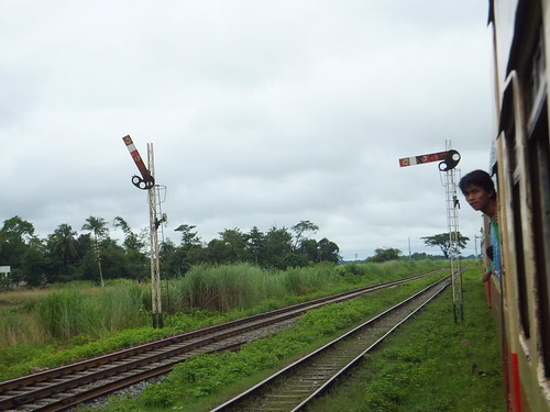
There seem to be endless variations on this theme. Some signal arms are tapered towards the pivot (as in typical American practice). The two white discs with the square 'hole' are still provided but, particularly on tapered signal arms, one 'spot' is sometimes deformed into an oval. Sometimes, a spectacle frame is provided, cut from steel sheet. Although all the signals I've seen are apparently 2-aspect, these cut-out spectacles appear with both two- and three- holes. No lighting is provided and there are no coloured spectacle glasses.

Upper quadrant signals at Bago with 'lower quadrant' arms.

At Bago, there are two signals of this pattern side-by-side, one with a 2-hole cut-out spectacle, the other with 3-holes. Both these arm-and-spectacle combinations are as in British practice (not mirror image) so, when arranged as an upper quadrant, look very odd when 'Off' (and couldn't easily provide the normal feature of the spectacle by changing the colour of the signal indication at night).

These two signals (like many others) are lattice-post - the remains of earlier signals, I suspect. Lattice posts look odd without a finial but most of them have disappeared. Other variations on signal posts include steel tube and, particularly for taller posts, two rolled sections (or rails) connected to form a built-up post. The example below has a built-up post surmounted by a tubular section and a finial. The arm of this signal has a nicely-proportioned spectacle made out of rod. As far as I can see, the push rod from the balance weight bar mounted fairly high would actually operate the arm as a lower-quadrant but the arm remained stubbornly 'On' as we rolled past! I'm not sure I'd be happy to use the rather lightweight signal ladder provided on this tall signal.

Tall signal with built-up post and tubular section.

Motor operation

Between Yangon and Bago, there a pair of motor operated semaphore signals - a down distant followed by a down outer home. Both signals had tapered (American-style) arms with 3-aspect spectacles and the rear of the arms was black with the chevron or bar white!

The Bracket Signal

Most of the network remains single track with passing loops, although around Yangon and on main lines there's double track which is still being extended.

At passing loops, there's normally a splitting home signal at each end of the station, situated at the toe of the points, allowing movements onto either Main or Loop line.

Typical 2-doll bracket at a passing loop between Bago and Kyaikto.

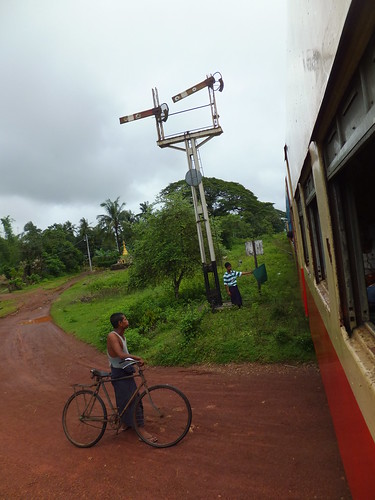
The picture above shows a typical 2-doll equal bracket. The main post and platform is fabricated from rolled sections but the dolls are lattice construction. The signal arms and pivots appear second-hand but the 'spectacles' are fabricated from rod - that on the left appears to be covered with gauze. Back blinders (which, on a signal with lighting, obscure a white 'back light' when the arm is 'Off') have been fabricated from sheet and rod, but there is no lighting. The arms are arranged as lower-quadrant and the right-hand arm is (sort of) 'Off'. The arms are operated by push rods from rocking shafts on the signal platform. The rocking shafts are operated by push rods from the ground, interlocked with the loop points. Normally, a single lever operates the signal with the appropriate arm 'selected' by the points interlock. The disc on the main post was once a speed restriction sign. The 'pointsman' is displaying a steady green flag.

Upper-quadrant 2-doll bracket signal at entrance to loop from the south at Naba.

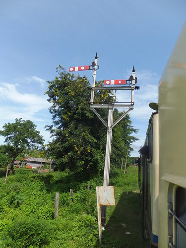
Elsewhere, similar 2-doll brackets are provided as splitting home signals at the entry to loops but with the signal arms arranged as upper-quadrant, as the example shown above.

Photographs

Burma: Semaphore Railway Signals.

The above set of pictures is part of a Collection Railways in Burma.

Road Repairs

The Wirtgen W250 Cold Milling Machine.

A stretch of road near me in Brewood had been 'patched' many times over recent years. Apart from the remarkable number of private cars the village seems home to, this road carries our bus service, the delivery vehicles servicing our local shops and a terrifying variety of agricultural machines, often with large trailers. As a result, 'patching' gave only brief improvement before the surface started breaking up again.

At the beginning of November, a circular was put out by the Council saying that the road in question was being closed for 8 days for essential work. So I was not surprised when I got up on 8th November to hear the muffled roar of a large diesel engine. I was quite impressed by the sight of the large yellow machine parked outside which was producing the sound. I recognised it as a 'Road Plane' and had a vague idea of its function in removing an old road surface but realised I knew little more and had not seen one operating. I had a closer look and spoke briefly to the machine operator as he filled the machine's water tank from a Fire Hydrant. The sheer size of the machine, carried on four tracked 'bogies', was notable as was the proliferation of colour computer screens provided to control the vehicle.

The machine was labelled as a Wirtgen product but it was being operated by Power Plane Limited. The machine was labelled as a 'W250' and the Power Plane website has brief details here, with links allowing download of two Wirtgen Documents in PDF format - the Technical Specification for the machine and a description of its use.

Before long, the machine in Brewood was demonstrating its ability to remove the old road surface by Cold Milling. I found the speed and accuracy of the process impressive.

The W250 at work.

In 1961 Reinhard Wirtgen, then aged 20, set up a haulage firm with one lorry. He developed the business into a construction firm, developing hydraulic shears for demolishing concrete structures and producing his own machines for road repairs. In 1970 he introduced 'Hot Milling' as a method for removing worn road surfaces and later 'Hot Recycling' as a method of repairing roads. 'Cold Milling' was introduced in 1979 and the business gave up contracting to concentrate on building machines at Windhagen, Germany. The Wirtgen Group now supplies machines worldwide and, in addition to Cold Milling machines, produces machines for Soil Stabilisation, Cold Recycling, Hot Recycling, Slipform Paving and Surface Mining. I'm afraid my ignorance of these techniques is almost total but the Wirtgen Site is a useful primer.

The W250 made short work of removing the old road surface, allowing other machines to lay the replacement surface. It was the massive yet sophisticated W250 which captured my imagination, but I should perhaps mention the Bomag BF600P Asphalt Finisher. Links on the Bomag webpage allow download of a leaflet and datasheet for this machine.

The Bomag BF600P Asphalt Finisher.

Bomag is a German company started in 1957 but it is now part of the much larger French group Fayat.

Photographs

Cold Milling Machine for Roads.

Thursday, 27 December 2012

H.M.S. Belfast

This is the view upstream from the bridge of H.M.S. Belfast, with the twin towers of Cannon Street station visible in the distance.

H.M.S. Belfast is a Light Cruiser of the 'Town' class ordered from Harland and Woolf in 1936 and commissioned in 1939. She served during World War II, including at the Battle of North Cape. After the War, she spent a number of years in the Far East. Following action during the Korean War, she was placed in reserve in 1952. In 1955, it was decided to modernise the ship which was re-commissioned in 1959. She was placed in reserve again in 1963 and, with the threat of scrapping, a trust was set up to preserve her. Wikipedia has an article about H.M.S. Belfast here.

Subsequently, she became 'the largest accessioned object' in the collection of the Imperial War Museums (there's a little about Museum Collections and 'accessioning' here).

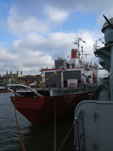
H.M.S. Belfast arrived in the Pool of London in 1971, to become a floating museum. It wasn't until 5th December 2012 I actually made a visit! I was surprised to find a large vessel moored alongside the museum ship - the S. A. Agulas. I later found out a little more about this ship (see below).

The Quarterdeck of H.M.S. Belfast, showing the Silver Bell.

The tour of H.M.S. Belfast is 'self-guided', but a helpful 'audio guide' is included in the admission price. I found the tour absorbing but tiring. If you do the full tour, there's a lot of stair-climbing. I was surprised how much of the ship is open to visitors. You can descend to boiler rooms and engine rooms, ascend to the Admiral's Bridge and the Ship's Bridge, see how the large armaments were fed with shells from the bowels of the ship and understand a little of how people ate, slept and worked on board. The ship is populated with quite life-like dummies illustrating all aspects of seamens' lives. To my surprise, I am able to strongly recommend a visit.

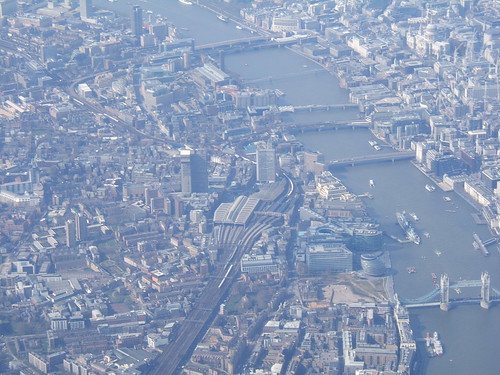
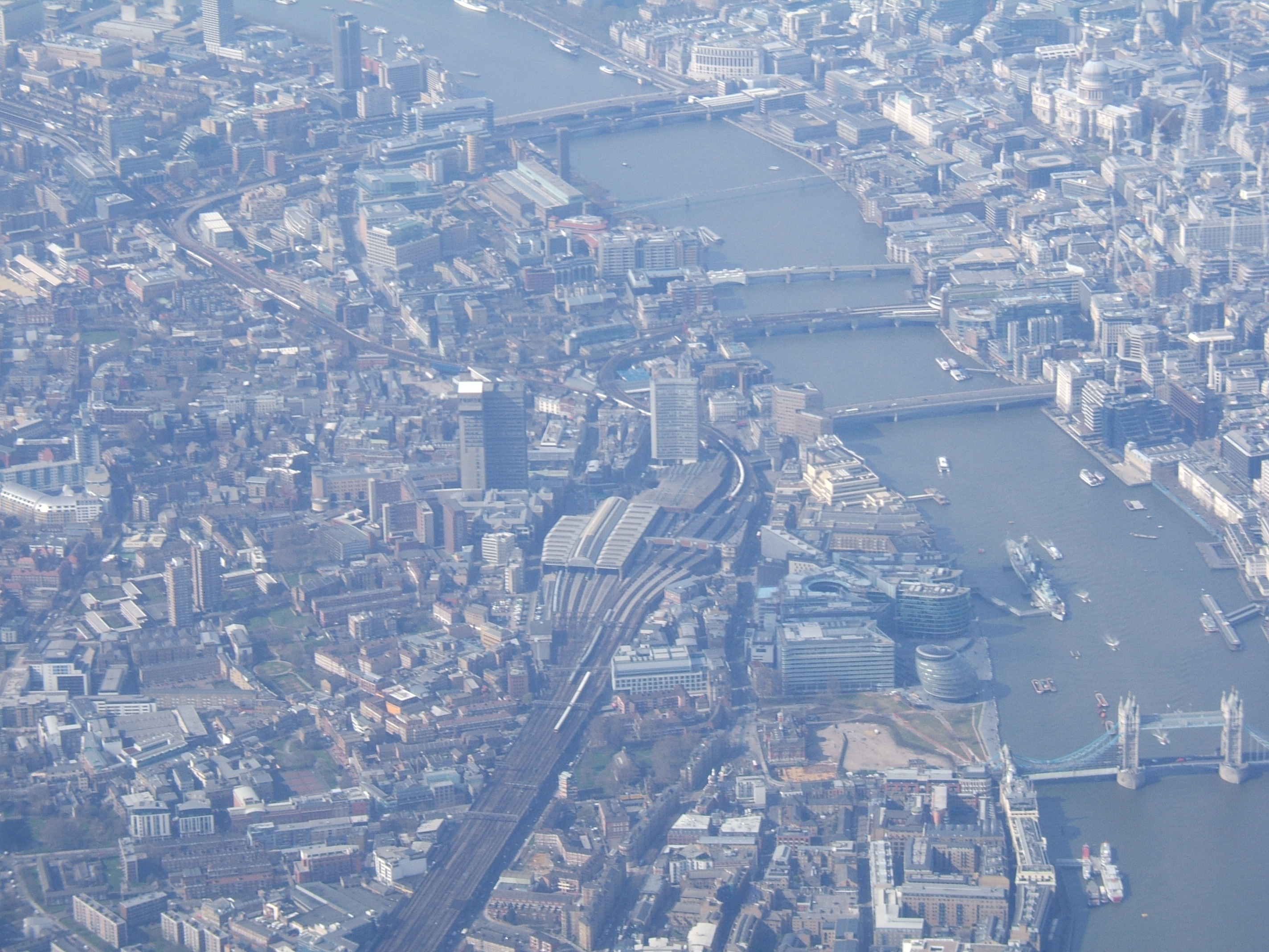
Aerial view looking upstream from Tower Bridge showing H.M.S. Belfast. London Bridge Station is in the centre with H.M.S. Belfast moored in the Thames to the right of the station. Picture taken 25-Mar-2009. Click here for high-resolution version of this picture. This is one of a set of pictures 'London from the Air'.

S. A. Agulas

View taken from H.M.S. Belfast showing the stern of S. A. Agulas and helicopter deck. The Tower of London is in the left background.

On my return home, I was able to find out a little more about the ship and its visit to London.

She is a South African ice-strengthened ship built in Japan, completed in 1978. It was a polar research vessel until the S. A. Agulas II was commissioned in March 2012 to take over this role, since when it has become a training ship. See the Wikipedia article. I traced the ship's recent movements from the useful site MarineTraffic.com (live information on the S. A. Agulas is here). She'd arrived at London on 29th November 2012 and then moved to the mooring alongside H.M.S. Belfast where I saw her. There's an interesting stop-frame video of this movement on You Tube here. The ship displayed two website addresses - www.seeingisbelieving.org and www.thecoldestjourney.org which explained the ship's current mission.

Seeing is believing is "is a global initiative to help tackle avoidable blindness" set up in 2003 as a collaboration between Standard Chartered Bank and the International Agency for Prevention of Blindness.

The Coldest Journey is an attempt by Sir Ranulph Fiennes and a team of explorers to cross Antarctica in winter with the aim of raising ten million dollars for Seeing is Believing. The progress of this expedition is being reported in a Blog on the The Coldest Journey website.

References

Imperial War Museums Guidebook for H.M.S. Belfast ISBN 978-1-904897-93-4.

Photographs

H.M.S. Belfast.
(Poor lighting in many parts of the ship made it difficult for me to take decent shots: the Guidebook listed above is full of excellent colour photographs).
London from the Air.

Wednesday, 19 December 2012

Bago to Kyaikto by Train

During my trip to Burma in 2012 (described in a series of posts here), I travelled by train from Yangon via Bago to Kyaikto. This post describes the journey from Bago to Kyaikto with a bit more technical detail. The first part of the journey, from Yangon to Bago, is described here. For this description, I've assumed the 'Down' direction is away from Yangon (although I've found one source which contradicts that). I've called the two signal boxes at Bago 'South' and 'North', based on the geography, but I don't know their official designation.

Journey made on Saturday, 8th September 2012

This post describes the second half of an uncomfortable (but interesting) journey from Yangon to Kyaikto.

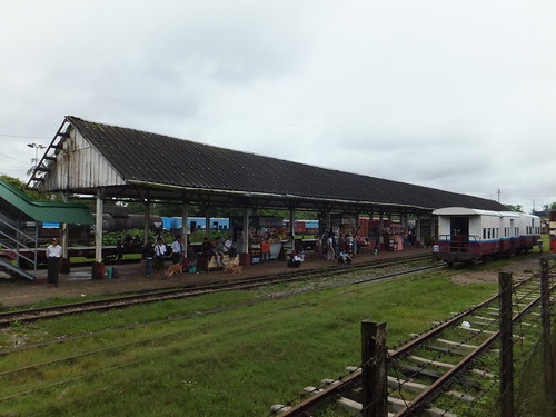
Bago Station. Four-wheel coaches in the central siding, freight vehicles in the background.

Bago is still an important station and has two mechanical signal boxes, one at each end of the station. When we stopped, large numbers of passengers got on and off. At least some of the people getting off were 'hawkers' selling drinks, food and all sorts of things to passengers. I presume they intended to catch the next train heading towards Yangon to continue the "at-your-seat service".

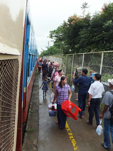
Passengers (and 'hawkers') getting on and off our train at Bago.

After a brief stop, our train continued, swinging violently over the pointwork near the North Signal Box as we made our way to the line to the Mawlamyine.

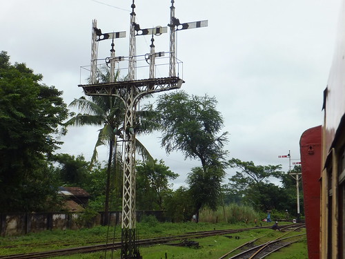
A magnificent 5-doll lattice-post bracket signal.

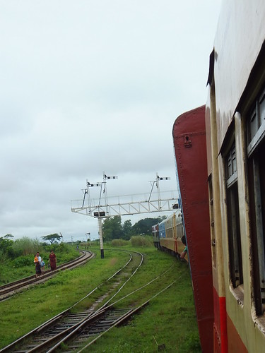
I managed a couple of shots of a magnificent 5-doll lattice-post bracket signal with 3 upper-quadrant main arms (the centre one with a ring which I assume means 'Goods Line') and two lower-quadrant miniature arms. All the arms had proper spectacles but no glass in the spectacles and no lighting. Balance weights (like most of the semaphore signals I've seen in Burma) were fitted at high level. Amazingly, four of the five dolls retained their elegant finials. From its style, this signal must have been imported from the U.K.

Leaving Bago on the line to Mawlamyine.

We passed under a steel truss gantry signal carrying what I presume are the Up Home signals for the North Signal Box. The signal dolls were lattice post but I couldn't get a proper look at the complete structure. Bago had one more puzzle for me. We were now travelling on the rightmost of three lines where the two on our left apparently formed the double-track to the north. Where you would expect the North Signal Box down starting signals, there were, indeed, two lattice posts (neither with finials), both fitted with the weird 'lower quadrant arm arranged as upper quadrant' I'd seen before, one with a 3-aspect spectacle, the other a 2-aspect spectacle!

Bago North Signal Box down starting signals.

It would take another three hours to reach Kyaikto on the single line, making our way through a number of stations with passing loops, sometimes taking the left track, sometimes the right. We made brief stops at some of these stations. About an hour out of Bago, we stopped at a slightly larger station with the normal passing loop and a third loop line presumably originally intended for loading/unloading goods vehicles because a single-lever ground frame controlling a trap point was provided at each end of the station. There was also an abandoned water column. Leaving this station, I almost missed our passage over a Scherzer Rolling Lift Bridge. After a further half hour of travelling, another line appeared on our left and trailed into our route. I think this formed a connection further north with the line from Bago to Mandalay. About two hours out of Bago, we stopped for a moment at a station where the loop line was blocked by a single open wagon. After another twenty-five minutes, we stopped at another station where the other line was occupied by a Yangon-bound train waiting for us to arrive, headed by D.1116.

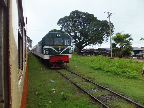
DD.1116 heading towards Yangon with a passenger train waits for us to clear the single line.

After a further half an hour, we arrived at Kyaikto where I got off exhausted with being thrown about.

If anyone can offer any clarification of Myanmar Railways practices, it would be welcome.

Train Timing and Photograph Locations

As yet, most of the stations are unidentified. There's a table below showing approximate journey time from leaving Yangon (hours:minutes), photo reference (prefixed 'DSCF') and brief description. There are links to the Sets containing these pictures in 'Photographs' below.

 
Elapsed Time Photo Ref Description
1:54 6009 Bago South Down Outer Home
1:55 6011 Bago South Down Home Gantry
1:57 6019 Bago Station
2:01 6021 Leaving Bago Station
2:02 6025 Bago North Up Home Gantry
2:12 6027 Down Home Bracket
2:13 6028 Station A
2:32 6032 Down Home Bracket
2:32 6033 Station B
2:33 6034 Ground frame exiting loop
2:48 6035 Down Outer Home
2:48 6036 Down Home Bracket
2:50 6037 Trap Point Ground frame
2:52 6038 Station C
2:54 6039 Trap Point Ground Frame
2:54 6042 Up Home Bracket
2:55 6043 Rolling Lift Bridge
3:13 6044 Down Home Bracket
3:22 6046 Down Outer Home
3:24 6048 Junction Ground Frames
3:22 6049 Junction Ground Frame
3:24 6050 Junction Ground Frame
3:35 6054 River Bridge
3:40 6056 Approaching Station
3:41 6057 Station D
3:41 6058 Station D
3:44 6059 Up Home Bracket
4:02 6065 Station E
4:03 6066 Leaving Station E
4:04 6067 Leaving Station E
4:24 6068 Arriving Station F
4:25 6069 Station F
4:25 6070 Station F
4:26 6071 Up Home Bracket
4:39 6072 Down Outer Home
4:40 6073 Down Home Bracket
4:42 6074 Station G
4:53 6075 Kyaikto Down Distant
4:54 6076 Kyaikto Down Outer Home
4:56 6077 Kyaikto Down Home Bracket
4:58 6079 Kyaikto Station

Photographs

Bago Station.
Bago to Kyaikto by Train.

[Revised 20-Dec-2012]