'Cumbria' is a six-coupled 'Austerity' saddle tank locomotive (Hunslet 3794/1953) owned by the Furness Railway Trust. There's a short history of the locomotive here and my article The 'Austerity' 0-6-0ST locomotive has more background on this locomotive class.
I first drove this engine during the Steam Gala in 2015 (described here) and I had another turn during the 'Santa Specials' (described here). But running a full 'Green Timetable' service is considerably more demanding and, at the end of traffic whilst Dave and I agreed we'd had a good day, we were also pretty exhausted.
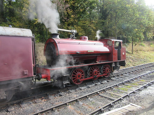 Battlefield Line Steam Gala, October 2015: 3794 'Cumbria', in its handsome lined-out 'Furness Indian Red' livery.
I signed on at seven o'clock (first departure was scheduled for 11:15) and was relieved to find 'Cumbria' already lit-up by Adrian L. I discovered that Dave H. was 'marked' as fireman but that he'd arranged a later start with Adrian agreeing to provide 'cover' until he arrived. Adrian and I spent a companiable couple of hours preparing the locomotive until Dave arrived.
We were using 'Welsh' coal which is, once again, available. The fearsome reputation of the Great Western Railway locomotives designed by Churchward was originally ascribed to the excellent steam-raising properties of the 'Welsh' coal normally used by that railway. But the locomotive exchanges of 1925 between the LNER and the GWR (touched on in my article 'Flying Scotsman') confirmed that the performance had more to do with sensible design proportions in boilers and cylinders, the use of 'long-lap, long travel' valves and good training of locomen, for the Great Western locomotives proved superior even when using the 'Yorkshire Hard' coal favoured by the L.N.E.R. But I was soon reminded of the one drawback of 'Welsh' - it's a rather soft coal prone to produce a lot of dust, suggesting the need for liberal use of the Coal Watering Pipe (an additional connection to the fireman's side injector with a cock allowing a jet of hot water to be directed around the footplate and bunker as required via a wire-reinforced flexible hose terminated in a nozzle, variously called, in different parts of the country, 'Pep Pipe', 'Slacking Pipe' or 'Degger'). Sadly, 'Cumbria' is not provided with a coal watering pipe so we were in for a dusty shift. Incidentally, whilst the LMS, LNER and SR installed automated coaling plants at their major depots, the GWR retained manual coaling using large rail-mounted 'tubs' to the end - supposedly because of the friability of 'Welsh' coal, rather than parsimony.
'Welsh' coal requires a modified firing technique. It takes a fair while to 'get going' but will then continue to give out high heat long after other coals have turned to ash. The new supply of 'Welsh' was smaller than the lumps I remember from over twenty years ago when I regularly fired 'Clun Castle' and 'Defiant' at Birmingham Railway Museum on driving experience courses and, as each lump absorbed heat from the firebed, it would swell and open resembling a glowing cauliflower head, creating steam for a long time. We didn't get this effect with the smaller lumps supplied on 'Cumbria' but the fuel did take its time and require plenty of air to produce steam (then it didn't want to stop!). The engine had been lit up in the shed so, as soon a we had about 20 p.s.i. of boiler pressure, I gingerly moved the locomotive outside the shed, in the hope of improving the drafting.
By 10:45, we had sufficient boiler pressure to ensure an effective steam brake, allowing us to move onto our 4-coach train waiting in platform 2, pausing on the way to fill the saddle tank at the water crane. This was a fairly time-consuming operation, since the pivoted arm of the crane carried a flexible plastic hose (this would have originally been riveted leather and always called 'the bag' by railwaymen) long enough to accommodate differing locomotive fillers, leaving it rather too long for the saddle tank of 'Cumbria'. Care was needed to dispose of the extra length of hose inside the saddle tank so that it didn't 'double up' when the water supply was turned on, impeding water flow.
Unfortunately we had to take water each time we ran round our train at Shackerstone during the day, ensuring that there was no time for a 'breather' throughout the shift. I didn't manage any photography, either.
The 'Green Timetable' is as below:-
| Shackerstone Dep | 11.15 | 12.30 | 13.45 | 15.00 | 16.15 |
| Market Bosworth Dep | 11.27 | 12.42 | 13.57 | 15.12 | 16.27 |
| Shenton Arr | 11.35 | 12.50 | 14.05 | 15.20 | 16.35 |
| Shenton Dep | 11.50 | 13.05 | 14.20 | 15.35 | 16.50 |
| Market Bosworth Dep | 12.00 | 13.15 | 14.30 | 15.45 | 17.00 |
| Shackerstone Arr | 12.10 | 13.25 | 14.40 | 15.55 | 17.10 |
As is often the case, even the first departure of the day was late, waiting for passengers. Thereafter, it was a struggle to keep to time because of the various speed restrictions on the line. Despite smart running round our train at each end of the line, the time required to take water meant that we lost further time, ending up at the end of the day around 20 minutes "down".
Notes on driving 'Cumbria'
When starting, any locomotive should be worked, at least briefly, in full gear, to maximise starting torque and start away smoothly. 'Full gear' can mean anything from 60-odd per cent cut-off to 80-odd per cent cut-off, depending upon the design. Once moving, I tend to 'link-up' (cutting off steam earlier in the piston's travel) quite quickly - with our four-coach train, 'Cumbria' was moving less than 200 tons total, yet the original design specified the ability to start 1,100 tons on the level, so an extended period of full gear was hardly warranted. Full-gear operation seeks to get lots of steam into the cylinders to generate power but, at the end of the piston stroke, that same steam has to be exhausted through the blast pipe and chimney and this can have the effect of 'choking' the locomotive, limiting acceleration.
But, of course, it's not that simple. The driver must consider various details of the design of the locomotive:-
First consideration, the Steam Valve: Originally, all locomotives used ordinary slide valves where the steam valve is held tightly against the port face by the pressure of steam in the valve chest. As locomotives became more powerful, valves became larger and, because the steam valves were 'unbalanced', significant power was absorbed in simply dragging the valve up and down across the port face and it became harder for the driver to adjust the cut-off when under steam.Following a little experimentation, I decided that, after a few 'chuffs' in full gear, I would select 'Linked-Up a Bit More' and then let 'Cumbria' get on with it, progressively increasing the regulator opening to 'Full First Valve' if I wanted more speed.
Some of the 'Pannier' class locomotives of the Great Western railway were notorious for difficulties in adjusting cut-off, unless the regulator was first closed, the cut-off altered and then steam was re-applied. There was a possible disadvantage with this technique in that, with the regulator closed, any unburnt particles emerging from the smoke tubes could fall into the blast pipe so, rather than close the regulator I tend to partially close the regulator, adjust the cut-off and then re-open the regulator to the original setting.
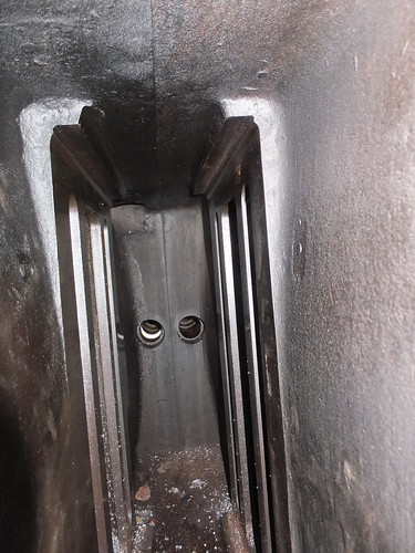
View inside the Valve Chest of an 'Austerity' under restoration showing (left and right) the rectangular steam and exhaust ports. Two (unbalanced) slide valves will be fitted back-to-back, each operated by a valve rod passing through the glands in the background.
'Balanced' slide valves sought to reduce these problems by reducing the area of the back of the valve exposed to live steam, reducing reducing the unbalance. The period of popularity of this type of valve was brought to a close by the development of successful 'Piston' valves, which are inherently 'balanced'.
View of valve chest of piston-valved locomotive under restoration in Insein Works, Burma.
Second consideration, the type of valve gear fitted to operate the steam valve: Although many, many designs of valve gear were produced, in the United Kingdom the two main contenders became the Link Motion (often called Stephenson Link Motion, developed by two employees of Robert Stephenson and Company, Williams and Howe) and Walschaert's Valve Gear (independently developed by the Belgian Egide Walschaerts and the German Von Heusinger).
Stephenson's Link Motion, as fitted to the six-coupled 'Austerities', can be designed to give pretty efficient steam distribution in both directions, although it's better suited to inside-cylinder locomotives. Don Ashton has produced an authoritative review of Stephenson Link Motion here. The picture below shows "Sapper's" driving axle and eccentrics which, like 'Cumbria', uses Link Motion.
"Sapper's" driving axle and eccentrics viewed from below. L-R: RH axlebox and underhung laminated spring, RH crank driven by (red) connecting rod, RH fore eccentric and rod, RH back eccentric and rod, LH back eccentric and rod, LH fore eccentric and rod, LH crank driven by (red) connecting rod, LH axlebox and underhung laminated spring.
Click here for a larger view
There's a little more on the locomotive 'Sapper' here.
Walschaert's gear, with separate lap-and-lead motion can be helpful for fast passenger designs but it is also ideal for outside-cylinder designs, keeping all the motion which needs examination and oiling readily accessible. Whilst I'm a great fan of Churchward's designs, I've always been puzzled that, when he did use Walschaert's gear on his 4-cylinder locomotives, he hid it between the frames where it was difficult to get at. Stanier, when he became Chief Mechanical Engineer at Derby, made sure his larger 2-cylinder designs, like the '8F' 8624 (shown below with a strange 'paint job'), used Walschaert's motion on the outside.
The public inauguration of the restored 8624 at Peak Rail on 23rd May 2009.
There's a little more about Stanier's '8F' design here.
Third consideration, the type of reverser used to adjust the valve gear: In express locomotives, reversers were often screw-operated, permitting precise adjustment of cut-off to suit extended periods of fast running.
Stanier Screw Reverser on 8624.
But freight locomotives, like the six-coupled 'Austerity' often had a 'lever' or 'pole' reverser - convenient when frequently changing direction during shunting although not really suitable for delicate changes of cut-off when running in one direction.
Of course, some locomotives had a 'power' reverser (usually steam-operated in this country) so that the driver only adjusted a small 'pilot' lever to control the actual reversing mechanism. Bullied 'Pacifics', as built, had 'power' reversers, which I've seen described as "the biggest liar on the footplate"! In a Beyer-Garratt locomotive, there are often four sets of motion to adjust on two different engine units, so power reversers were common on these designs.
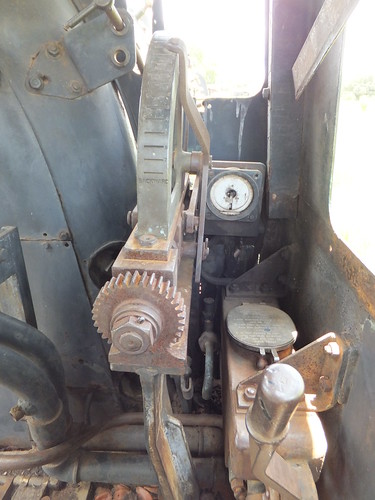
Hadfield Reverser on 20th class No. 708, built Beyer Peacock on display in Livingstone Railway Museum, showing control for steam reverser and cut-off indicator.
Some locomotives with a conventional 'lever' reverser had lots of slots implying the possibility of fine adjustment of cut-off. But I never met a driver who cared much what cut-off he operated at - he would just set the driving controls so that the engine 'felt right'. The reversing quadrant on 'Cumbria' subscribed to this common-sense approach to setting cut-off - in addition to the 'Mid Gear' notch, it had (in each direction) notches for 'Full Gear', 'Linked-Up a Bit' and 'Linked-Up a Bit More'.
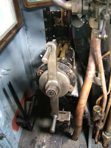

Typical lever reverser on an 'Austerity' tank.
There's a bit about regulators in the posts Locomotive Regulators and The Best Laid Schemes ....
'Cumbria' was in need of some care and attention, which added to our difficulties. All the controls were rather stiff - water cocks took some strength to set correctly, lever reverser catch handle was stiff, even the valve spindle on the vacuum brake application valve needed some manual assistance. The fireman's side injector was temperamental to set, causing additional use of the (fairly reliable) driver's side injector. After shutting off steam, prior to a speed restriction or station stop, this often meant the additional task of 'setting' the driver's side water cock for the fireman at the same time as judging the vacuum brake application.
Like many industrial locomotives later fitted with an ejector to allow the operation of vacuum-braked passenger trains, the steam supply cock to the ejector required 'tuning' to obtain 'best vacuum'. This often means 'throttling-back' the steam since excessive steam supply can produce turbulence in the body of the ejector, impairing the desirable 'laminar fluid flow' and reducing the vacuum created. Depending upon the installation details, other events (such as operation of the safety valves or putting on a ejector or even adjusting the blower) can alter the level of vacuum created. In the case of 'Cumbria', it was desirable to pay close attention to the vacuum gauge as she would occasionally suddenly lose a few inches of vacuum, creating a partial brake application, for no discernable reason, resulting in furious 'twiddling' of the steam supply, to try to regain the "sweet spot".
I think all enginemen like the challenge of a slightly recalcitrant locomotive - but not too much of a challenge.
