Thursday, 6 June 2013

The Liverpool Overhead Railway

In 2009 I wrote briefly about the long-gone Liverpool Overhead Railway in the post Liverpool.

This panorama from the Liverpool Overhead Railway 'Map and Guide of the Railway and Docks' shows the route of the railway and the stations. Click on the image for a larger view.

In the 1980s, I came across the preserved intermediate trailer coach of the pattern rebuilt by the Liverpool Overhead Railway at 'Steamport', which occupied the disused steam shed at Southport. The 'Steamport' operation subsequently relocated to Preston as The Ribble Steam Railway and I don't believe this coach survived.

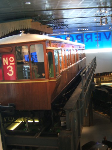
Liverpool Museums originally had the preserved Driving/Motor car displayed in the Transport Gallery of the former museum but, when this closed, the coach was placed in storage. I caught up with this coach in 2010, described in my post here, whilst museum staff were preparing the vehicle for display in the new Museum of Liverpool. I was allowed to take a series of pictures.

I finally saw the Driving/Motor car displayed on 1st December 2011 when I was invited to attend the Official Opening of the new Museum of Liverpool, described in my post here. There are a few pictures of the car on display here.


The preserved Liverpool Overhead Railway driving motor car is displayed in the Museum of Liverpool in a setting representing the supporting girder structure and a station.

One bogie of each Driving/Motor car had a single 60 h.p. electric motor. Formation was normally 3-car with two Driving/Motor cars and a single Trailer car but, of course, 2-car operation was possible.

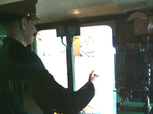
Liverpool Overhead Railway coach: view of the driving compartment with (dummy) driver.

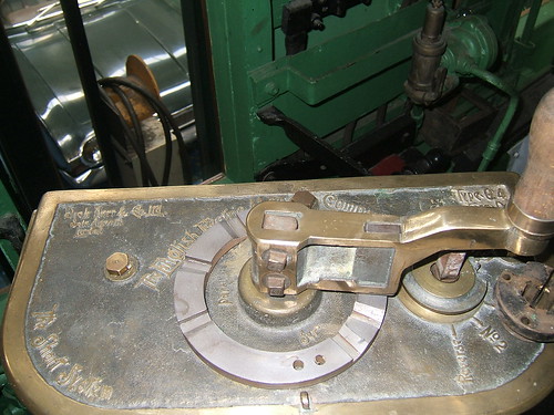
Top view of the Controller for the Traction Motors fitted in the driving compartment.

The controller now fitted appears to be more modern than that originally fitted. The cast brass top plate of the controller carries the name 'The English Electric Mfg. Co. Ltd', together with 'Dick Kerr & Co. Ltd, Sole Agents, London' and a cryptic reference to 'The Short System'. The type of the Controller is also marked on the top plate - Type Q4, Form D.

The Controller has two controls - the speed regulator is provided with a large, fixed handle whilst the master controller has a removeable handle which was moved from cab to cab when the driver 'changed ends' at the end of the line.
The speed regulator rotates from the one o'clock position (Off) through a number of 'Series' notches to five o'clock. Movement from five o'clock to eight o'clock places the motors in parallel and further notching up is possible, until the stop at eleven o'clock which should produce the maximum design speed of 30 m.p.h.

The master controller has a number of positions - Forward, No. 2, No. 1, Off, No. 1, No. 2, Reverse. I believe the 'No. 1' and 'No. 2' positions are to allow the set to continue with only one serviceable motor.
Dick, Kerr & Company were taken over by English Electric in 1919 (see the Wikipedia articles on Dick, Kerr and Company and English Electric).

When first built, the trains had no air compressor and a trainborne air receiver was re-charged at the terminus. But later electric compressors were added. A 2-pipe system is fitted and the driver was provided with two air pressure gauges. The brake application valve was placed at the top of an upright branch pipe in the cab, in what I should think was a fairly inconvenient position. The driver was required to stand whilst driving.

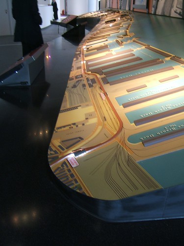
The Museum of Liverpool display allows visitors to enter part of the coach and sound effects are provided. Additional information on the Liverpool Overhead Railway is presented adjacent to the coach and there is a splendid model of the route, where white lights (representing trains) move up and down the route, pausing briefly at each station.


The large model of the Liverpool Overhead Railway viewed from the Seaforth Sands end. The River Mersey is on the right.

Book References

[1] 'The Liverpool Overhead Railway 1893-1956' by Charles E. Box, revised by Adrian Jarvis, published Ian Allen (ISBN 0 7110 1183 4).
[2] 'The Docker's Umbrella: A History of the Liverpool Overhead Railway' by Paul Bolger, published by the Bluecoat Press (ISBN 1 872568 05 X).
[3] 'An Illustrated History of Liverpool's Railways' by Paul Anderson, published Irwell Press (ISBN 1-871608-68-6).

My pictures

Liverpool Overhead Railway Driving/Motor Car.
Royal Visit to the Museum of Liverpool.

Wednesday, 5 June 2013

Day Trip to Ely

On Saturday 1st June 2013, I made a day trip to Ely by rail to attend the Open University Degree Ceremony in Ely Cathedral (where Ann was "being presented" having graduated). It's a little surprising that such a cross-country journey is feasible these days but there's a regular Birmingham - Stansted Airport service which calls at Ely.

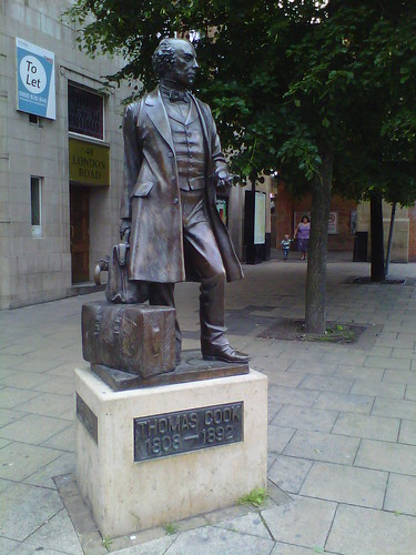
I reached Birmingham using the Virgin service from Wolverhampton. This was more than I could easily have done the previous (Bank Holiday) weekend when Wolverhampton was closed to trains and all departures were by bus. It continues to appall me that chunks of our railway system close down every holiday period for engineering works of one sort or another. This is such a contrast with matters when I was young when the railway put on extra trains and virtually every vehicle that could 'turn a wheel' was pressed into service (there's a flavour of this sort of activity in my post Excursions at Sedgeley Junction). The idea of the railway excursion is credited to Thomas Cook who organised the first known major excursion from Leicester to Loughborough in 1841.


Statue outside Leicester station of Thomas Cook.

Executing the change at Birmingham New Street meant negotiating the recently-changed arrangements there. Birmingham New Street station is being modernised. There's a website here about the project which modestly describes itself as "transforming Birmingham's New Street station to create a stunning 21st century transport hub". Halfway through the project, the first half of the new concourse was opened on the 28th April 2013 so it's all a bit incomplete and unfamiliar.

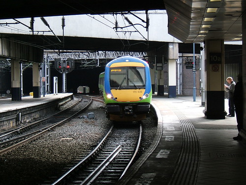
A class 170 from Leicester arriving at Birmingham New Street in 2009.

However, the 3-car class 170 diesel multiple unit was already waiting in the platform and we slowly set off 'right time'. Once we'd untangled ourselves from what I still think of as the "new" arrangements around Proof House Junction and established ourselves on the Up Derby, speed picked up. We passed Saltley Power Signal Box and then the futuristic-looking West Coast Control Centre.

Each time I travel by rail now, I'm reminded of just how difficult is is to observe the 'passing scene' from a train since most trains have air conditioning and no opening windows at all. Seats appear to be carefully aligned in relation to the available windows so as to minimise the number of seats with a decent view outside. This makes taking pictures from a moving train - the "drive by shooting" - difficult and the results disappointing. One of the attractive features of the early 'Modernisation' series of diesel multiple units was the window at the end of the passenger compartments allowing passengers to look through the driving compartment to the track ahead (or behind). Of course, that sort of nonsense has been stamped out. In modern diesel-powered trains, the noise and vibration from the underfloor engines is often too high for comfort, as well.

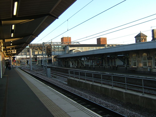
Our train continued on the former Midland Railway route. Approaching Nuneaton, you struggle to spot signs of the former Abbey Street station which I remember, with its all-wood 'Midland' signal box. From here, trains are routed to a new island platform tacked on to the Up side of the largely London and North Western station which serves the West Coast route. Originally, there was a freight avoiding line here which, I think, was sometimes used by passenger excursions.

Nuneaton: View from the new island platform looking south, with the old station on the right.

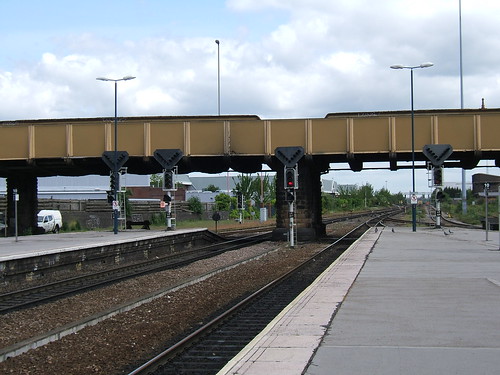
We made good time to Leicester. I'm always amazed at just how simplified the railway layout is, compared with what I remember from steam days. After a wait of a few minutes, we set off northwards, passing the very spartan-design of the Power Signal Box.

Leicester station, looking north. Click above for an uncropped picture showing the Power Signal Box on the right.

At Syston, we turned right for the Midland Railway line to Peterborough. As we made our way along the branch, I was pleased to see semaphore signals. I spotted the elderly Midland-origin mechanical signalboxes at Market Harborough and Oakham - I'm not sure what others survive.

The Midland route approaches Peterborough from the north, meeting the electrified East Coast Main Line about six miles north of the city and then running parallel to it to Peterborough station. There was quite a lot of alteration work in hand around the station. Quite a few passengers alighted or boarded here. Leaving the station, the Midland route diverged from the electrified route to Kings Cross on a falling grade before taking a broad sweep to the left and crossing the River Nene. On the right, I could see 'Railworld', a rather curious amalgam of Transport Centre and Wildlife Haven, "promoting sustainable travel and development". The trackbed of the London and North Western Railway route can be seen. This originally converged with the Midland route here. A few yards to the west I could see the Nene Valley Railway's eastern terminus (called, appropriately enough, 'Peterborough Nene Valley') which is built on that redundant trackbed. We then passed under the impressive girder bridge carrying the electrified lines and, after about a mile and a half, left the control area of Peterborough Power Box. We returned to semaphore signalling, initially controlled by a delightful mechanical signal box at Kings Dyke. We were now in Great Eastern Railway territory and the signal boxes provided a suitable reminder.

The next large town was March, about 15 miles from Peterborough, and we crossed fifteen level crossings (plus a couple of Accommodation Crossings) before arriving at March. I first visited March with my mother when I was about ten years old. She had a visit to make in the area and we travelled by train. I remember an impressive station with elaborate umbrella roofing over the platforms and a selection of unfamiliar Eastern region steam locomotives. Returning in 2013, only two platforms remain in use and the rest of the station is semi-derelict with tracks removed. I think there were originally four through platforms and a couple of bays.

March was famous for its automated hump marshalling yard at Whitemoor, built by the L.N.E.R. in 1929 and well-described in 'Mike's Railway History here.

Whitemoor Hump Yard (from a British Rail Film Strip produced in 1950).

I never saw the hump yard and it was completely removed by the mid 1980s. However, a new yard has been built, principally to serve as one of the ugly 'Virtual Quarries' now used for ballast storage.

There are still two mechanical signal boxes at March - March East Junction and March South Junction - controlling a pleasing array of mechanical signals. Beyond March, I didn't spot the boxes at Stonea and Manea but I think they survive, Manea serving as a 'Fringe Box' to the Power Box at Cambridge. Fourteen miles beyond March, the overhead electrified line from Kings Lynn joined on our left at Ely North Junction. This is remotely controlled from Cambridge, as is Ely station itself, two miles further on, where I left the train. The train then continued 'under the wires' to Cambridge and then Stansted Airport.

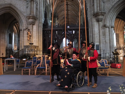
I had an interesting day as Ann's guest at the Degree Ceremony in Ely Cathedral. Ann and Dean are involved in the Sealed Knot as members of Sir Gilbert Hoghton's Companie of Foote and a number of members of this Royalist regiment attended in costume and posed for photographs, by arrangement, before the Degree Ceremony. This created quite a bit of interest!

Hoghton's in the Nave of Ely Cathedral.

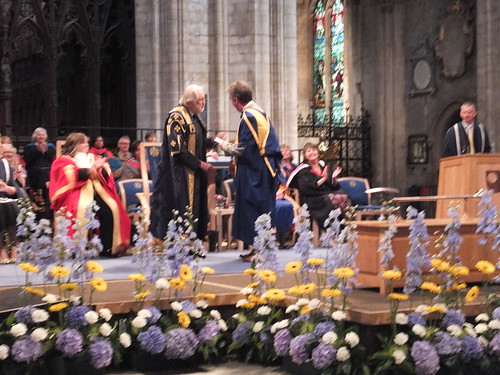
The ceremony itself started at 2.30 p.m. and almost 300 graduates were presented to the Chancellor of the Open University, Lord Puttnam of Queensgate CBE. In the evening, a further group of graduates were to be presented at a similar ceremony.

A graduate being presented to Lord Puttnam.

Later, John, Ann, Dean and I enjoyed an excellent meal (as John's guests) at 'The Boathouse' riverside restaurant. Then, a short walk took me back to Ely station, where I had time to take a few pictures before catching the 20:15 to Birmingham. At Birmingham, I'd just time to catch a 'Virgin' Pendolino service back to Wolverhampton.

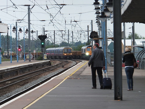
Ely station in the evening: A Class 365 for King's Lynn on the Down Main passes a freight waiting in the Down Goods Loop.

Map References

There are historic signal box diagrams for some of the route I travelled in the Signalling Record Society publications 'British Railways Layout Plans of the 1950's'.

Wolverhampton to Birmingham is included in 'Volume 11: LNW Lines in the West Midlands' (ISBN: 1 873228 13 9).
Saltley to Nuneaton Abbey Street is included in 'Volume 16: ex-MR lines Derby (excl) to Barnt Green, Burton to Leicester (excl), and branches' (ISBN: 1 873228 22 8).


For details of the route in the 21st century, refer to:-

'Railway Track Diagrams Book 4: Midlands & North West', Second Edition, published by Trackmaps (ISBN: 0-9549866-0-1).
'Railway Track Diagrams Book 2: Eastern', Third Edition, published by Trackmaps (ISBN: 0-9549866-2-8).

My pictures

West Midland Railways.
Nuneaton.
Leicester area.
Ely Station.
Ely & the Degree Ceremony.

Tuesday, 4 June 2013

'Black 5' to Birmingham

I consider myself fortunate to have experienced steam haulage on the main line when it was an everyday experience - when I was young, almost all the trains I saw were steam hauled! I'm just sorry I'm not able to give more details of these trips. I rarely noted even the engine number and dates and timings are usually not recorded. Sometime in the 1950s, one of my day trips was from Wolverhampton to Liverpool Lime Street.

I'd acquired a 'Clarion' portable tape recorder and hoped to make some sound recordings on the journey. The recorder was fairly basic - I would have liked a 'Uher', as used by the B.B.C., but that was way beyond my resources. The 'Clarion' recorder had capstan drive, giving nominally constant recording speed of three and three quarter inches per second (unlike the competing Grundig 'Cub' machine which simply drove the take-up spool at constant speed, giving a variable recording speed so that recordings could only be played back on the 'Cub'). However, 'wow' and 'flutter' performance was fairly poor. The microphone had no protection against wind so recordings at speed were fairly hopeless.

I don't remember the outward journey and can't tell you how I spent the day, although I'm sure to have walked to Pierhead at some point and probably made a trip on the Mersey Ferries. I'll try to describe what I remember of the return trip.

It was starting to get dark as I made my way back to Lime Street Station to catch a Birmingham train as far as Wolverhampton. The route (as it remains today) was through Runcorn to Weaver Junction where we would join the West Coast Main Line, then through Crewe to Stafford and finally onto the Stour Valley Line as far as Wolverhampton.

With a few minutes in hand before departure, I walked the length of the platform to check the motive power. It was a rather grubby 'Black 5' and I chatted to the friendly crew for a minute or two. I would have mentioned that I intended to make recordings on the journey. The first vehicle was a brake composite so I tucked myself in the corridor on the left near the leading door with the window wide open.
Click for larger image.
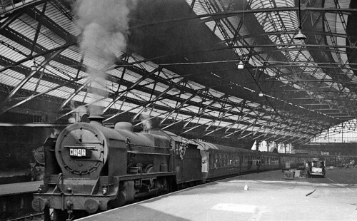
Not a 'Black 5' but otherwise a similar working from Liverpool Lime Street in 1959. LMS Fowler 6P 4-6-0 No. 45515 'Caernarvon' on the 10.05 express to Bournemouth West (Photo: Ben Brooksbank via Wikimedia Commons [CC-BY-SA-2.0]).

The colour light signal at the end of the platform came 'Off' and, about right time, the Guard gave the 'Right Away'. With a short whistle, the driver eased the regulator open and the train moved out across the pointwork at the station throat to reach the Up Fast line. There wasn't the trace of any slip as the driver 'opened her up' and the train settled into the 1 in 93 bank to Edge Hill. Originally this stretch had been a tunnel but it was then opened-out into a deep rock cutting, spanned by numerous bridges to carry the various roads. The crisp Stanier exhaust really echoed off the rock walls as we blasted up the grade.


Gradient diagram Weaver Junction - Liverpool Lime Street, with our starting point at Lime Street on the right.

We ran through the platform at Edge Hill at a fair speed and crossed to the 'South' Lines at Edge Hill No. 2 signal box, now running on the level. Looking to the left, there was just time to see the 'Waterloo' goods lines (leading through a tunnel under the city to the northern docks) and the extensive sidings before passing Edge Hill No. 3 signal box where we branched right onto the 'Crewe' lines. The curve, now rising again at climb of 1 in 93, took us under the 'Wapping Goods' lines and then, on our left, there was a view of the smoky gloom around Edge Hill Shed, with its distinctive coaling stage.


Again, not a 'Black 5' but '5X' 45418 passes Edge Hill shed with an Up Express for Crewe direction (Photo: Lamdelz)

We plunged under another bridge, this time the 'Circular Goods' lines (these allowed freight trains to and from Crewe direction to reach the unique 'Gridiron' marshalling yard without interfering with either passenger trains on the 'Crewe' line or traffic on the Liverpool and Manchester route) and soon reached the summit at Wavertree Junction. Now on a downhill stretch, we sped through Mossley Hill and clattered over the pointwork at Allerton Junction, where a branch to Hunts Cross diverged on our left. There was then an easy climb at 1 in 296 through more crossings at Speke Junction. By this time, we were running well. It was a dark, clear night and, under these favourable conditions, I remember noticing (not for the first time) just how visible the semaphore signal indications (red, yellow, green) were at a distance, considering they were produced by a tiny paraffin flame in the signal lamp (there's a description of semaphore signal lamps here). After around three miles, the track levelled through Halebank water troughs. I can't remember whether we took water but, only having come around 10 miles from Lime Street, we may not have done - it depends how full the tender was when we started. If we had taken water, I would have been careful to close the windows beforehand to avoid a possible drowning! We then ran downhill for a mile to Ditton Junction. This was quite an important location with two signal boxes, six platforms, extensive sidings and numerous bracket and gantry semaphore signals.

Ditton Junction had some notoriety as the location of a serious accident in 1912 when the driver of a Down train who was fairly unfamiliar with the location misread signals and failed to slow when crossing to the Slow line, derailing the train with considerable damage. The seriousness was compounded by fire in the wreckage. The complete Railway Accident Report by Lieutenant-Colonel Yorke is available here, on the excellent Railways Archive site.

Another uphill section of 1 in 114 took us across Ditton Viaduct and then, on the level, we crossed the River Mersey and the Manchester Ship Canal by Runcorn Railway Bridge. This bridge was built in 1868 to a design by William Baker and features double-web lattice girder contruction on stone abutments. There's a Wikipedia article about the bridge here. Leaving the bridge, the line climbed at 1 in 145 to our first station stop at Runcorn, about two and a half miles beyond Ditton Junction.

After a brief stop, we received the 'Right Away' and set off. The line was cut through a sandstone cutting, with about half a mile at 1 in 101, easing slightly to 1 in 115 for another mile. The engine was being worked fairly hard to accelerate away from our stop and we were certainly 'raising the echoes'. We passed Halton Junction (where the line to Frodsham Junction and Chester diverged to our right) a little over a mile from our stop having built up a fair speed. Almost two miles further on, we passed our highest point at Sutton Weaver, then we descended for about a mile and a half at 1 in 101 to the small signal box at Birdswood, situated near the flyover junction where our line crossed over the main lines to Warrington and ran alongside the Up Main, descending at a gentle 1 in 337 for almost a mile and a half before finally converging with the main lines outside Weaver Junction signal box.


Gradient diagram Madeley - Weaver Junction.

We crossed the River Weaver and the Weaver Navigation on the double-track Dutton Viaduct. This stone viaduct, comprising 20 arches each of 60 foot span, was built in 1837 for the Grand Junction Railway.


Dutton Viaduct (Photo: N.R.M.).

For the next 11 miles, our route was generally uphill, but not too demanding - 1 in 330 was about as stiff as it got. The double track section continued past the viaduct for about another mile and a half to Acton Bridge station, where the route became four-track, paired by direction, for two miles to Hartford Junction. We clattered over the pointwork where a spur diverged to the left to join the former Cheshire Lines Committee from Chester to Altrincham. On our left were the I.C.I. sidings but, in the darkness, the lines of bogie hopper vehicles which always filled the sidings could not be seen. Back on double track, we dived under the bridge carrying the C.L.C. route and started to reduce speed, for we were booked to stop at Hartford station a mile further on. Quite a few passengers left the train here.

As we stood in the platform, it was all very peaceful for a moment, with just a quiet sizzling from the engine. The driver leaned out and waved. I turned towards the rear of the train to see who he was waving at but I couldn't spot anyone. The driver waved again, more urgently and I realised the signal was for me. "Now what?" I thought as I dropped down onto the platform and went forward. The fireman opened the cab doors and beckoned me onto the footplate. The driver briefly acknowledged me but carried on looking back along the train. When the fireman closed the cab doors, it finally dawned on me that I was to travel with them. Our next stop was Crewe, twelve miles on. As soon as the driver got the 'Right Away' from the guard, he made a vigorous start and quickly worked the speed up.

I'd previously had a number of short rides on the footplate (pottering around on station pilots or yard shunters). Around Morecambe, I'd had a number of rides on a Stanier 0-4-4T working push-pull trains (mentioned in the post Steam around Morecambe). But I'd never had a trip like this one - on the main line, at speed and at night.

When the fireman opened the firedoors to put a charge of coal on, the cab was flooded with intense, white light and, even standing at the back of the cab, I could feel the searing heat. I thought to myself "I must try to remember everything I see" but the noise, the vibration and the heat when the firedoors were open made it very difficult to concentrate. I was fascinated and terrified at the same time.

Three miles of double track took us past Winsford Junction and its goods loops, another mile and a half to Winsford station where, once again, the line became four-track, paired by direction. This four-track section would take us right into Crewe.

I had a fair idea of the layout of the driving controls in a Stanier cab but everything looked more mysterious in the dark, being bounced around and deafened. Although we were running pretty fast, the Fireman was only firing occasionally and the rest of the time he was on the tip-up seat keeping a look-out for signals. The driver was making no further alterations to the regulator or cut-off and most of his attention was focussed along the side of the taper boiler, peering at the line ahead
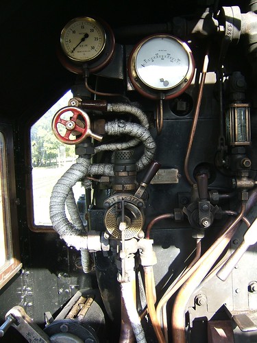

View of the Driver's side of the cab in a Stanier locomotive.

Two and a half miles beyond Winsford, we passed Minshull Vernon. The station was long-gone, only grass-covered platforms remained flanking the slow lines but the signal box was still there to "shorten the block". Here, the line became level right into Crewe. Another two miles took us past Coppenhall Junction, where there were crossovers to allow some switching between Fast and Slow lines. Another three miles would bring us into Crewe station. I knew we were close when I saw Crewe Coal Yard signal box. This was an 'Air Raid Precautions' style box on the Up side where the Liverpool Goods Independent lines branched off the Slow lines and tunnelled under Crewe North Junction to emerge near Salop Goods Junction. We'd left semaphore signals behind for a while - all the main signals through Crewe were colour light. As we approached Crewe North Junction, the Driver told me to tuck myself in the back corner of the cab up against the tender until the "coast was clear" so I didn't see much of our arrival into what was (and I think will always remain for me) Platform 4.

When we stopped, the Fireman had a good look both ways along the platform until it was safe for me to slip back to the train without the Driver or Fireman getting disciplined for their kindness. It was some years before I read the saying (probably in one of Professor Tuplin's books) "There's always somebody at Crewe on the look-out for trouble" but that night I already understood the meaning very well. Babbling my thanks, I clambered off the footplate when bidden and quickly slipped back into the leading coach. I'd abandoned my possessions (including the 'Clarion' tape recorder) in the front coach when I'd hurriedly left the train at Hartford. Fortunately, everything was still there, undisturbed. My legs were still trembling and my head was a whirl so I didn't pay a great deal of attention to the rest of the journey back to Wolverhampton, I'm afraid.

What happened next?

That was a wonderful experience which I still remember (even if the details are a bit vague). My initial interest was in railway signalling, rather than locomotives and it was many years before I began a serious study of steam locomotives, when I was already in my forties. I've explained the circumstances in the post 'Lion'. Eventually, I got to drive a few Stanier locomotives on preserved lines.


Jan in the cab of 'Black 5' 45337 at Peak Rail (Photo: Sheila Rayson).

The Route

In the 1950s, apart from Lime Street and Crewe, the route was mainly controlled by semaphore signals, manual signal boxes and Absolute Block Signalling. We passed the following signal boxes on our way from Lime Street to Crewe:-

Liverpool Lime Street
Edge Hill No.2
Edge Hill No.3
Wavertree Jn.
Allerton Junction
Speke Jn.
Woodside Siding
Ditton Jn. No. 2
Ditton Jn. No. 1
Runcorn
Halton Jn.
Sutton Weaver
Birdswood
Weaver Jn
Acton Bridge
Hartford Jn.
Hartford
Verdins Sidings
Winsford Jn.
Winsford Goods Yard
Winsford
Minshull Vernon
Coppenhall Jn.
Crewe Coal Yard
Crewe North Jn.
Crewe No. 3

More details about each of these signal boxes can be found in the 'British Railways Layout Plans of the 1950's' series below.

Map References

You can find detailed signal box diagrams for the route I travelled in the excellent series of publications from the Signalling Record Society 'British Railways Layout Plans of the 1950's'.

Liverpool Lime Street to Weaver Junction is included in 'Volume 9: LNW Lines Crewe to Euxton Junction, Liverpool to Manchester (and associated branches)' (ISBN: 1 873228 11 2).
Stafford to Crewe is included in 'Volume 1: ex-LNWR main line, Euston to Crewe' (ISBN: 1 873228 00 7).
Wolverhampton to Stafford (excluding Stafford) is included in 'Volume 11: LNW Lines in the West Midlands' (ISBN: 1 873228 13 9).

If you want to see what remained of the route in 2005, refer to 'Railway Track Diagrams Book 4: Midlands & North West', Second Edition, published by Trackmaps (ISBN: 0-9549866-0-1).

Tuesday, 28 May 2013

Liverpool Lime Street Station

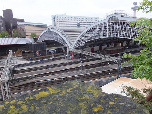
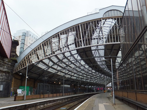
Lime Street: the Train Sheds viewed from the car park off Lord Nelson Street.

The railways around Liverpool have always had a fascination for me, particularly because of Liverpool's position at one end of the Liverpool and Manchester Railway which was the "first main line passenger railway in the world".

Then and Now

Click for larger image.
Liverpool Lime Street on 13th June 1959. View looking westward towards the buffers, with LMS Fowler 6P 4-6-0 No. 45515 'Caernarvon' ready to leave on the 10.05 express to Bournemouth West, which will run via Crewe, Birmingham New St., Bath and the Somerset & Dorset line (Photo: Ben Brooksbank via Wikimedia Commons [CC-BY-SA-2.0]).

Liverpool Lime Street on 19th May 2012. View westward towards the buffers on Platform 8 with 4-car EMU 350 115 (almost hidden) ready to leave for Birmingham New St.

Brief History

The Liverpool and Manchester Railway opened in 1830 but the original passenger terminus at Liverpool was not at Lime Street but at Crown Street, Edge Hill. First Class passengers were provided with a horse-drawn carriage service between Crown Street and Dale Street, near the commercial centre of the city. From Edge Hill, there was also an inclined tunnel just over 2 km long cut through sandstone, shale and clay to Park Lane Depot near Wapping Dock. Locomotives were initially prohibited from this tunnel so passenger and goods trains descended to Park Lane by gravity, controlled by Brakemen on the train and trains were hauled back up to Edge Hill by rope, using stationary steam winding engines.

The success of the railway meant that these arrangements proved inadequate and a further Act authorised a new tunnel from Edge Hill to Lime Street Station. This tunnel was just over 2 km long, principally through sandstone, and inclined at a gradient of around 1 in 93. Further winding engines were provided at Edge Hill (together with a new station) and the approach to Lime Street was rope worked from 1837 until 1879. The first station buildings at Lime Street (completed in 1836) were designed by John Foster Junior and had a 2-storey classical facade.

In 1845 the Liverpool and Manchester Railway was absorbed by the Grand Junction Railway which, the following year,became part of the London and North Western Railway.

In 1849, the original Lime Street Station was replaced by a design by Sir William Tite extending along Lord Nelson Street. This included an iron segmental-arched train shed by Richard Turner, following his success in creating the Palm House at Kew.

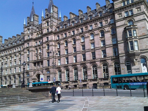
The present train sheds were built in two stages. The north shed by William Baker has a span of 200 feet - the largest in the world at the time it was built. It was completed in 1867, together with the North Western Hotel in French Renaissance style by Alfred Waterhouse which is now accommodation for university students.

Alfred Waterhouse's French renaissance frontage masks William Baker's north train shed.

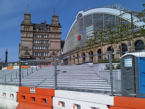
The south train shed (by Francis Stevenson and E. W. Ives) followed in 1879.

View of the road frontage of the south train shed.

The Railway Act of 1921 grouped the railways into the 'Big Four' (L.M.S., G.W.R., L.N.E.R. and S.R.) and Lime Street became part of the L.M.S. Upon Nationalisation in 1948, the London Midland Region of British Railways took over many of the L.M.S. assets.

The Approach to Lime Street

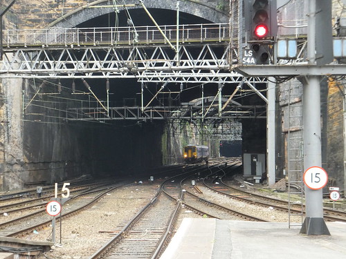
After 1879, locomotives started to haul trains in and out of Lime Street Station. Conditions passing through a busy 1-mile long tunnel were hardly ideal and, in 1882, the tunnels were 'opened-out' leaving a deep cutting with various short tunnels and a myriad of criss-crossing bridges carrying streets. For trains leaving Lime Street, with a 'green' fire and an engine not yet 'warmed through', the gradient of 1 in 93 for about a mile up to Edge Hill was something of a challenge to enginemen throughout the steam era,


Gradient diagram Weaver Junction - Liverpool Lime Street, showing (right) the approach to Lime Street on a 1 in 93 incline.

Lime Street: Looking towards Edge Hill from Platform 7 with a DMU approaching the local platforms on the north side of the station.

Signalling

The 'A.R.P.' style signal box at Liverpool Lime Street in May 2012. The route is set for a departure from Platform 9 to the Up Fast.

The Westinghouse Style 'L' 'All Electric' power frames introduced electrical interlocking between miniature levers as a development of the earlier Style 'K' which had miniature levers but mechanical interlocking. The London, Midland and Scottish Railway installed a number of the Style 'L' frames, including the one at Liverpool Lime Street. In 1940, an order was placed for a 95-lever frame for the new 'ARP' style signal box at Lime Street with 31 point levers, 58 signal levers and 6 spare levers.

A similar Style 'L' miniature lever frame in Crewe North Junction.

For more information about the Style 'L' frame, refer to Book Reference [1] 'The Style L Power Frame'. For more information about Liverpool Lime Street signal box, click here. This page is part of the splendid site 'Westinghouse Brake and Saxby Signal Co. Ltd miniature power lever frames'.

External Links

Liverpool Lime Street railway station (Wikipedia).
Liverpool Lime Street (Network Rail).
Liverpool and Manchester Railway (Wikipedia).
London and North Western Railway (Wikipedia).
London, Midland and Scottish Railway (Wikipedia).

Map References

You can find a detailed signal box diagram for Liverpool Lime Street in the excellent series of publications from the Signalling Record Society publication 'British Railways Layout Plans of the 1950's'. Liverpool Lime Street is in 'Volume 9: LNW Lines Crewe to Euxton Junction, Liverpool to Manchester (and associated branches)' (ISBN: 1 873228 11 2).

For details of the layout in 2005, refer to 'Railway Track Diagrams Book 4: Midlands & North West', Second Edition, published by Trackmaps (ISBN: 0-9549866-0-1).

Book References

[1] 'The Style L Power Frame' written and published by J. D. Francis 1989 (ISBN 0 9514636 0 8).
[2] 'Liverpool & Manchester Railway 1830-1980' by Frank Ferneyhough published by Book Club Associates.
[3] 'A Regional History of the Railways of Great Britain': Volume 10 The North West by G. O. Holt, Second Edition published by David & Charles (ISBN 0946537 34 8).

My Pictures

Liverpool: The City.
Liverpool Area Railways.

Thursday, 23 May 2013

Railway Signalling in Britain: Part 5 - Signal Arm, Slot and Lamp Repeaters

Each signalman is responsible for monitoring the signals he controls. In a previous part of this series (Part 4 - Semaphore Signal Aspects by Night) I outlined how some signals leading to the advance section were visible to the signalman from the front whilst the use of 'Backlights' allowed the signalman to confirm that some signals in the rear of his box were displaying a 'Stop' aspect. But not all signals could be observed by the signalman like this. In particular, the all-important Distant signals were generally not visible from the signal box.

Just as electrical techniques were adopted by railways to create the Block System, electricity offered methods of repeating the aspect shown by a signal back to the signal box and proving whether the signal lamp was lit.

1. SIGNAL ARM REPEATERS

Detecting the Arm Position

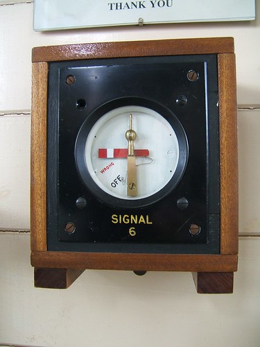
The signal arm was coupled to an electrical contact box fixed to the signal via a solid rod. As the arm moved, a moveable contact in the contact box moved between two fixed contact. Depending upon the type of contact box, the moveable contact had linear or rotary motion. In each case, one contact was closed with the arm 'On', the other contact was closed with the arm 'Off'. In between 'On' and 'Off', no contact was made and the signal aspect was described as 'Wrong'. By providing an electrical supply at the signal location, the contact box could connect a direct current to a repeater wire taken back to the signal box. The return for this direct current was via the earth, usually with a bond to one of the running rails. The connections were arranged so that, with the signal arm 'On' one polarity would be connected to the repeater wire, with the signal arm 'Off' the opposite polarity would be connected. With the signal arm in an intermediate ('Wrong') position, neither polarity would be connected to the repeater wire.


Western Region pattern linear contact box with cover removed and displayed as a working demonstration (Exeter West box, Crewe).

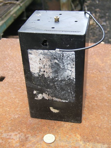
During steam days, there was rarely electric power available trackside so batteries (normally primary cells with large capacity) were provided, typically mounted in a battery box at the side of the track near the signal post.


Typical battery used on railways (One pound coin for scale).

Transmitting the Arm Position to the Signal Box

In general, electrical circuits on railways (whether for telegraph, telephone, block signalling or signal repeating) were carried on an 'Open Wire' route as bare copper wires strung between porcelain insulators mounted on the cross-arms of a series of 'telegraph poles' extending alongside the railway. The repeater wire from a signal would join the main 'Open Wire' route either as a bare wire connected to a porcelain insulator on the signal post or as an insulated cable. The 'Open Wire' route was then used to lead the repeater wire back to the supervising signal box.

Indicating the Arm Position to the Signalman

At the signal box, current of one polarity in the repeater wire represented 'On', current of the other polarity represented 'Off' and no current implied the signal was 'Wrong'.

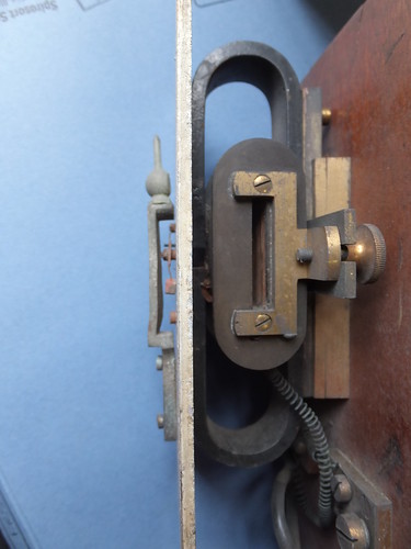
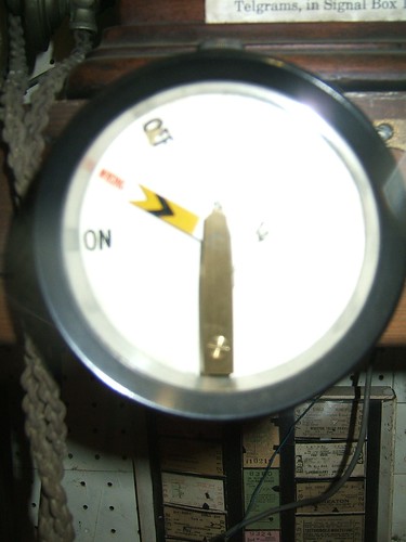
Indication was made using a galvanometer where the repeater wire current passed through an electrical coil with a slot arranged through the middle. A small metal 'flag' was mounted in the slot on a pivot so as to swing to the left or right of the 'rest' position under the influence of the magnetic field produced when the associated signal was 'On' or 'Off' and a current flowed through the repeater wire. The direction of movement of the 'flag' depended upon the polarity of the current. The pivot extended through the front plate of the indicator so as to turn the miniature signal arm on the front of the indicator as the current moved the 'flag'.


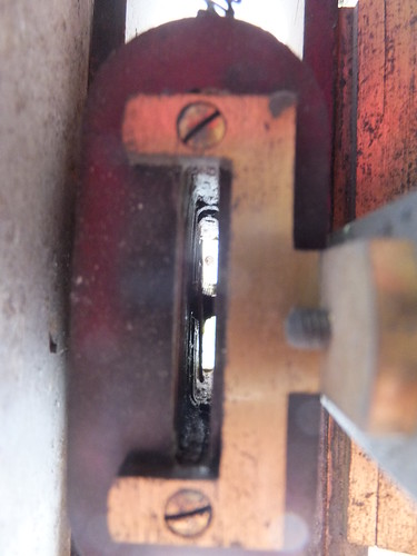
An early signal repeater viewed from the right with the wooden case removed. Left to right: Cast metal model signal post and miniature signal arm visible to signalman, metal front plate, oval mounting bracket, electrical coil (note slot), wooden backplate.


Close-up of the electrical coil showing the slot and the pivoted metal 'flag' which deflected under the influence of the magnetic field so that the position of the miniature signal arm corresponded with the actual signal arm being repeated.

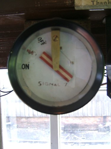
In early indicator designs, the galvanometer was mounted in a glass-fronted wooden cabinet which was fixed near the lever controlling the repeated signal. More modern indicators were more compact, in a circular glass-fronted housing simply screwed to the front of the block shelf so as to be readily visible to the signalman.

Examples of Signal Arm Indicators

Typically, indicators had a model of a signal, with the miniature arm moving up or down to indicate 'Clear', according to the design of the actual signal being repeated.


Upper-quadrant Distant Signal Arm Repeater in a round case (Displayed at Shackerstone Railway Museum).


Signal Arm Repeater for a lower-quadrant stop signal. Here a round case has been mounted in a wooden box to allow fitting where there is no block shelf (Part of a display at Exeter West box, Crewe).

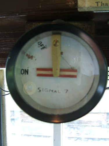
Sometimes, there was no attempt to model a signal post, but the paint scheme of the miniature arm would reflect the full-size signal.


Signal Arm Repeater intended for use with a Subsidiary Signal - showing 'Wrong' (In use at the Battlefield Line).


Signal Arm Repeater intended for use with a Subsidiary Signal - showing 'On' (In use at the Battlefield Line).

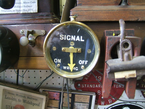
A more abstract display featured a simple pointer. In the example below, the pointer is painted yellow to indicate its use on a Distant Signal. This type of indicator with a pointer was also used where a lever controlled a colour-light, rather than a semaphore, signal.

A Signal Arm Repeater with a yellow pointer, rather than a signal model. The round case is metal (Displayed at Shackerstone Railway Museum).

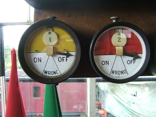
The two indicators below have the upper half of the front plate painted to represent the signal type. In this case, round engraved labels fitted inside the case neatly identify the controlling lever but identification was often by an external engraved label mounted adjacent to the indicator.

Signal Repeaters mounted on Block Shelf (Lever 1, Up Distant, Lever 2, Up Home at Exeter West box, Crewe).

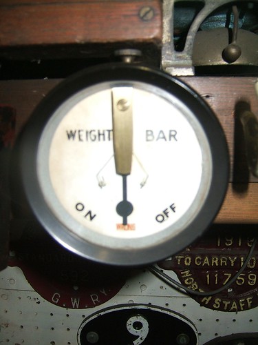
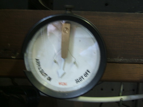
Where a lever controlled a slot (for instance, a distant signal mounted under a stop signal controlled by another box), the position of the weight bar, not the arm, was repeated and the pointer was shaped to represent the weight bar.


Weight Bar Repeater for slotted signal (Displayed at Shackerstone Railway Museum).

However, if the slot was associated with a Stop signal, it was sometimes necessary to give assurance to the signalman that the signal arm (not just the slot) was correctly 'On'. Contact boxes were fitted on both the arm and the weight bar and inter-wired as necessary.

In this case, the Repeater can indicate that not only the Weight Bar (Slot) is 'On' but that also the associated signal arm is actually 'On' (Displayed at Shackerstone Railway Museum).

2. SIGNAL LAMP REPEATERS

Pyrometers

Paraffin signal lamps were normally continuously lit. The hot air produced by the small flame rose through the chimney at the top of the lamp housing. The Pyrometer was a device fixed in the hinged lid of the housing so that the hot air passed over it, closing an electrical contact. If the flame became extinguished, the electrical contact opened.

Metals expand when heated. The measure of how much each metal expands is called its Coefficient of Linear Expansion. A Bimetal strip is made of two metals with markedly different coefficients of expansion alloyed together. If such a strip is mounted with one end clamped and the other free, when it is heated, the strip will bend away from the metal with the larger coefficient of expansion. This movement of the strip when heated can be used to close an electrical contact. This is the principle used by simple thermostats.

The picture below shows one design of pyrometer used in signal lamps. The mounting frame is in the form of a ring. Two bi-metal strips are clamped to the frame at one end only, electrically insulated from the frame. The strips extend across the ring so as to be exposed to the rising hot air. When the bimetal strips are heated, they deflect and make contact with a bridging piece also mounted on the frame but insulated from it. Two flexible bare copper wires are attached to the fixed ends of the bimetal strips, insulated by porcelain 'beads' threaded onto the wires. The two wires lead to two substantial insulated electrical terminals mounted on the hinged top of the lamp housing. Provided the lamp is burning, there is electrical contact between the two insulated electrical terminals mounted on the lamp housing. If the lamp is extinguished, the bimetal strips cool and move away from the bridging piece, breaking the electrical circuit.

Close-up of a Pyrometer mounted in the hinging top of a lamp housing (Displayed at Shackerstone Railway Museum).

Electrical batteries were provided at the signal location so that the pyrometer could connect a direct current to a lamp repeater wire taken back to the signal box, provided the lamp was lit. The return for this direct current was via the earth, usually with a bond to one of the running rails. On signals with more than one arm, it was possible for two or more pyrometers to be wired in series so that an alarm was given if any of the group of lamps was 'Out'.

Transmitting the Lamp Status to the Signal Box

The arrangements for transmitting lamp status were exactly as described above for 'Transmitting the Arm Position to the Signal Box'

Indicating the Lamp Status to the Signalman

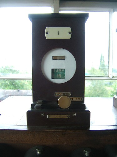
At the signal box, current flowing in the lamp repeater wire represented 'Lamp In', no current represented 'Lamp Out'. Indication was made using a galvanometer similar to that described above for 'Indicating the Arm Position to the Signalman', except that it had only two positions, not three. To quickly alert the signalman to a lamp failure, the 'Lamp Out' indication would sound a bell or buzzer until the signalman acknowledged the alarm by operating a switch.

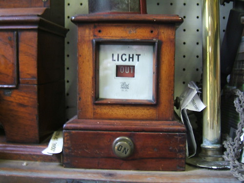
Early indicator designs featured glass-fronted wooden cabinets (as for Signal Arm Repeating), fixed near the lever controlling the signal being repeated. This eventually evolved into a modular system, outlined below.

Examples of Signal Lamp Indicators


Great Western Lamp Repeater in wooden case. Note the switch to silence the alarm (Lever 1, Up Distant, at Exeter West box, Crewe).

Midland Railway Lamp Repeater in wooden case. Note the Midland Wyvern and letters 'M.R.' (Displayed at Shackerstone Railway Museum).

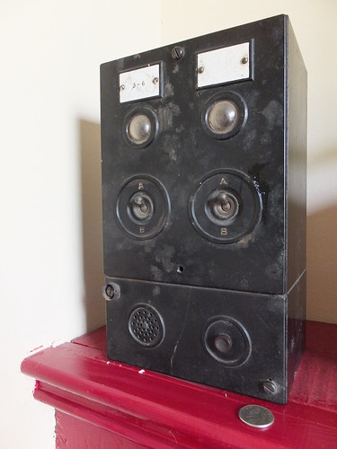
As more signals were equipped with lamp repeaters, the need for a more compact arrangement for displaying lamp status was met by a modular system. The picture below shows the lamp repeater for Bloomfield Junction which was the simplest possible form, comprising a common Test/Buzzer unit with a larger 2-circuit display unit mounted on top. More complex installations required one common unit plus a number of 2-circuit display units bolted together. Normally, indicator lamps were out and there was no buzzer alarm. The indicator lamps could be tested by pressing the test pushbutton on the common unit. Failure of a signal lamp would light the appropriate indicator lamp and sound the buzzer. The buzzer was silenced by operating the toggle switch next to the lit lamp to the 'B' position. When the signal lamp was restored, the buzzer would sound until the toggle switch was placed in the 'A' position.


Modular Signal Lamp Repeater used by British Railways (10p coin for scale).

3. COMBINED SIGNAL ARM AND LAMP REPEATERS

J. W. Fletcher patented a combined signal arm and lamp repeater which was used on the London and North Western Railway. Only one wire was needed between the signal and signal box, rather than two (one for arm repeating, one for lamp repeating). Despite this advantage, more modern installations usually adopted the 2-wire approach.

The signal arm detection operated in the manner described in section 1 above. Failure of the signal lamp placed a resistance in series with the repeater wire, restricting the current flowing. The galvanometer repeating the arm position was designed to be sufficiently sensitive to carry on working correctly on the reduced current but a second galvanometer controlling the Lamp In/Lamp Out display window was designed to show the 'Lamp Out' condition with the reduced current. When the signal lamp was restored, the pyrometer contact would short out the resistor and the increased current caused the display window to show 'Lamp In'.


Fletcher's Arm and Lamp Repeater (displayed in Crewe Heritage Centre) only required one wire from the signal to the signal box.

4. INDICATORS USED FOR OTHER PURPOSES

2-position and 3-position indicators were used for various other purposes. The examples given below are not exhaustive.

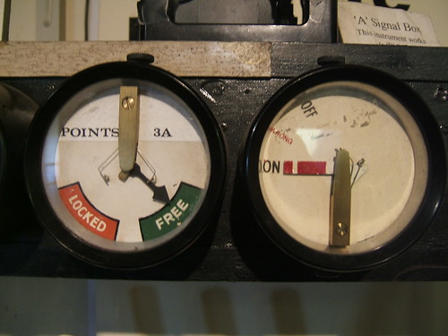
2-position indicators were also used, for instance, to show that at electrical release was available at a Ground Frame.

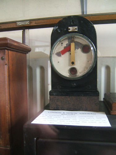
Indicator for remote electrical release on a set of mechanically-operated points side-by-side with an Arm Repeater for an Upper Quadrant Stop Signal (displayed in Crewe Heritage Centre).

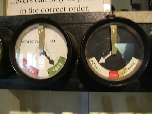
The picture below shows a 2-position indicator used to show whether a remote electrical release was available. This is side-by-side with a 3-position indicator used to repeat the position of a set of points provided with Electrical Detection.

Indicator for remote electrical release on a set of mechanically-operated points and Repeater for a set of points with Electrical Detection (displayed in Crewe Heritage Centre).

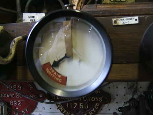
Before track circuiting was common, a 'Fireman's Call Plunger' was sometimes provided to alert the signalman to a train detained at a signal. A 2-position indicator was used to remind the signalman of the waiting train. The indication was cancelled when the signal was cleared, allowing the train to proceed.

'Train Waiting at Signal' Indicator (Displayed at Shackerstone Railway Museum).

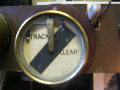
Even when track circuiting was installed, it was frequently done piecemeal. If only a few track circuits required indication to a signalman, they would normally be indicated to the signalman by a series of 2-position indicators provided with a distinctive black bar which moved through 45 degrees. The black bar was horizontal when there was no current through the galvanometer (representing 'Track Occupied').

Track Circuit Indicator showing 'Track Clear' (Displayed at Shackerstone Railway Museum).

My Pictures

There are pictures of signalling equipment in various sets and the links below are not exhaustive:-
Shackerstone Railway Museum.
Signalling at Peak Rail.
British Railway Signalling Equipment.
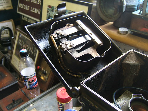
Exeter West Signal Box.
Signalling Displays at Crewe Heritage Centre.

More

Go to Part 6 - Mechanical Operation of Points

[Link to Part 6 added: 18-Sep-2014]