
This sign (in a factory washroom) neatly reminds workers to take responsibility for their own safety. Or, at least, it would if somebody hadn't broken the darn mirror!
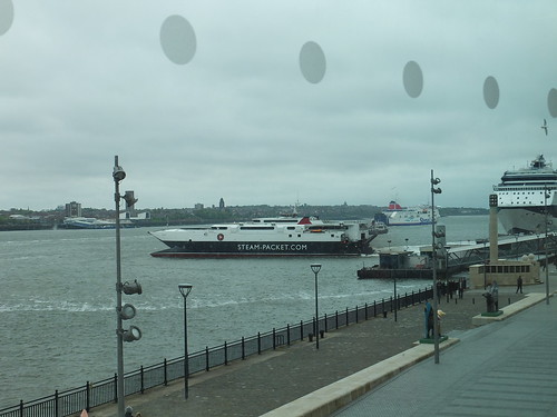
The Museum of Liverpool. I'm still not a fan of the building's architecture (it's sometimes called "the dented shoebox") but it is certainly attracting the public.
The 29th A.G.M. of the Old Locomotive Committee (OLCO) was held in the Museum of Liverpool on Saturday, 18th May 2013.
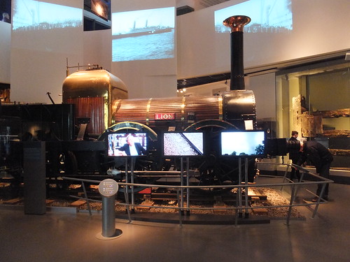
The museum was opened to the public on 19th July 2011, prior to the Official Opening by Her Majesty the Queen, accompanied by His Royal Highness The Duke of Edinburgh, on Thursday 1st December 2011. There's a report on the Official Opening here. The new museum has been a spectacular success in terms of number of visitors and has become the country's most visited museum outside London. Star museum exhibit 'Lion' received an Engineering Heritage Award in 2012.
Through the courtesy of the Museum's Transport Curator Sharon Brown, this was the second time that the A.G.M. has been held at the Museum. There's a brief report on the A.G.M. in 2012 here.
Once again, we were accommodated in one of the Education Rooms on the first floor with a glazed wall offering a panoramic view of the River Mersey. Sharon had also arranged a supply of tea, coffee, biscuits and cakes for which members were very grateful.
Liverpool may no longer be the 'Great Port' celebrated by the museum gallery where 'Lion' is displayed but there was still considerable activity around Pierhead. The Celebrity 'Infinity' had docked just after 6.00 a.m. that morning from Dublin, giving its passengers a few hours to explore the city before leaving around 8.00 p.m. the same day for Belfast. The Isle of Man Steam Packet Company's futuristic-looking wave-piercing catamaran 'Manannan' has an interesting history outlined in a 'Wikipedia' article.
The Museum frequently provides talks to visitors about the history of the locomotive 'Lion' and at noon the OLCO Chairman, John Brandrick, delivered an interesting talk next to 'Lion'.
The OLCO Chairman talks about 'Lion'.
There are also audio-visual presentations about 'Lion' both on-demand and automatically every half-hour (see the article here for more information).
The Chairman of OLCO, John Brandrick, opened the formal A.G.M. at 1.30 p.m. and welcomed those attending. The Agenda items were dealt with enthusiastically and the Election of Officers resulted in no changes to those serving in the previous year. There was animated discussion, particularly when 'Any Other Business' was reached. The meeting was closed at 4.00 p.m. Members of the Old Locomotive Committee will receive details of the proceedings in due course.
My photographs taken around the museum on the day are here.
My (expanded) set of pictures around Liverpool are here.
My (expanded) set of pictures of the railways around Liverpool are here.
There are a number of articles in my blog about 'Lion' and her 'supporters club' OLCO - you can find them all here.
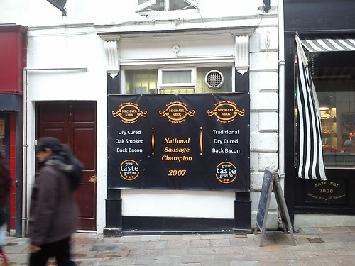
Wolverhampton is the home of an award-winning butcher's shop, Michael Kirk, which was founded in 1934. There are usually a couple of chalkboards outside the shop with details of special offers. I couldn't resist taking a (rather fuzzy) picture below of the message I saw the other day.
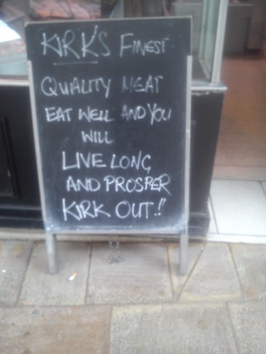
All part of the frenzy surrounding the release of Star Trek Into Darkness, I suppose.
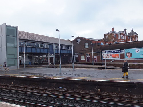
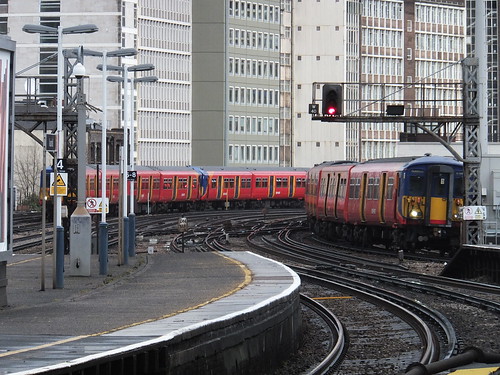
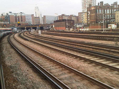
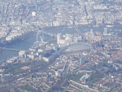
On 11th and 12th April 2013, I re-visited some of the lines around Clapham Junction, London, which has the distinction of being "Britain's Busiest Railway Station" (in terms of number of trains). Trains today are principally Electric Multiple Units of various classes.
Then and Now
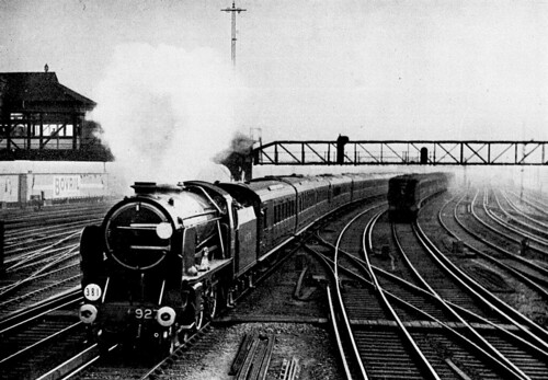 In the 'Southern' era, 'Schools' 4-4-0 No. 927 hustles the Down 'Bournemouth Limited' express through Clapham Junction, passing a Down electric train. Clapham Junction 'A' signal box, built over the tracks, is visible on the left (Photo: British Railways).
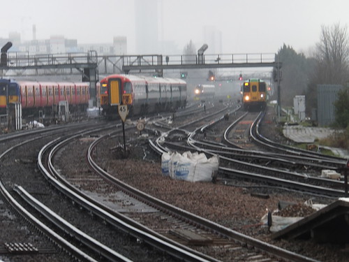 A modern view taken from (more or less) the same location, looking towards the centre of London. Two multiple units are approaching and two heading away. Clapham Junction 'A' signal box has gone and the area is controlled from Victoria Area Signalling Control (which is actually situated at Clapham Junction).
Pre-Grouping History
Clapham Junction would be impressive if only for the number of trains using the station but looking the historical reasons for the tangle of lines in the area makes the location even more interesting. The London and South Western Railway were first on the scene, with their initial line from Nine Elms to Southampton. A branch to Richmond was opened next. As traffic grew, an extension from Nine Elms to Waterloo Station was brought into use.
Both the London Brighton and South Coast Railway and the London and Chatham Railway (which later became the South Eastern and Chatham Railway) had their initial terminal stations at London Bridge, which was fairly convenient for businessmen travelling to the City. But these railways had aspirations to create a new terminus in the West End, north of the Thames. A number of new lines fulfilled these ambitions.
The London Brighton and South Coast Railway constructed a new line from East Croydon to Clapham Junction which then ran parallel to the South Western lines before crossing under them to head north to the River Thames. The South Eastern and Chatham Railway extended its lines to similarly cross under the London and South Western route to Waterloo. The new route for the two railways crossed over the Thames on Grosvenor Bridge, to reach the two side-by-side stations at Victoria.
The success of Victoria brought congestion, neccessitating the widening of Grosvenor Bridge. The South Eastern and Chatham Railway paralleled their original line to Victoria with a new route between Battersea Pier Junction and Wandsworth Road which, in addition to crossing over the South Western lines to Waterloo, crossed the original route twice! The London Brighton and South Coast Railway built its own high-level parallel routes between Battersea Pier Junction and Clapham Junction with a new branch at Battersea Park to Wandsworth Road.
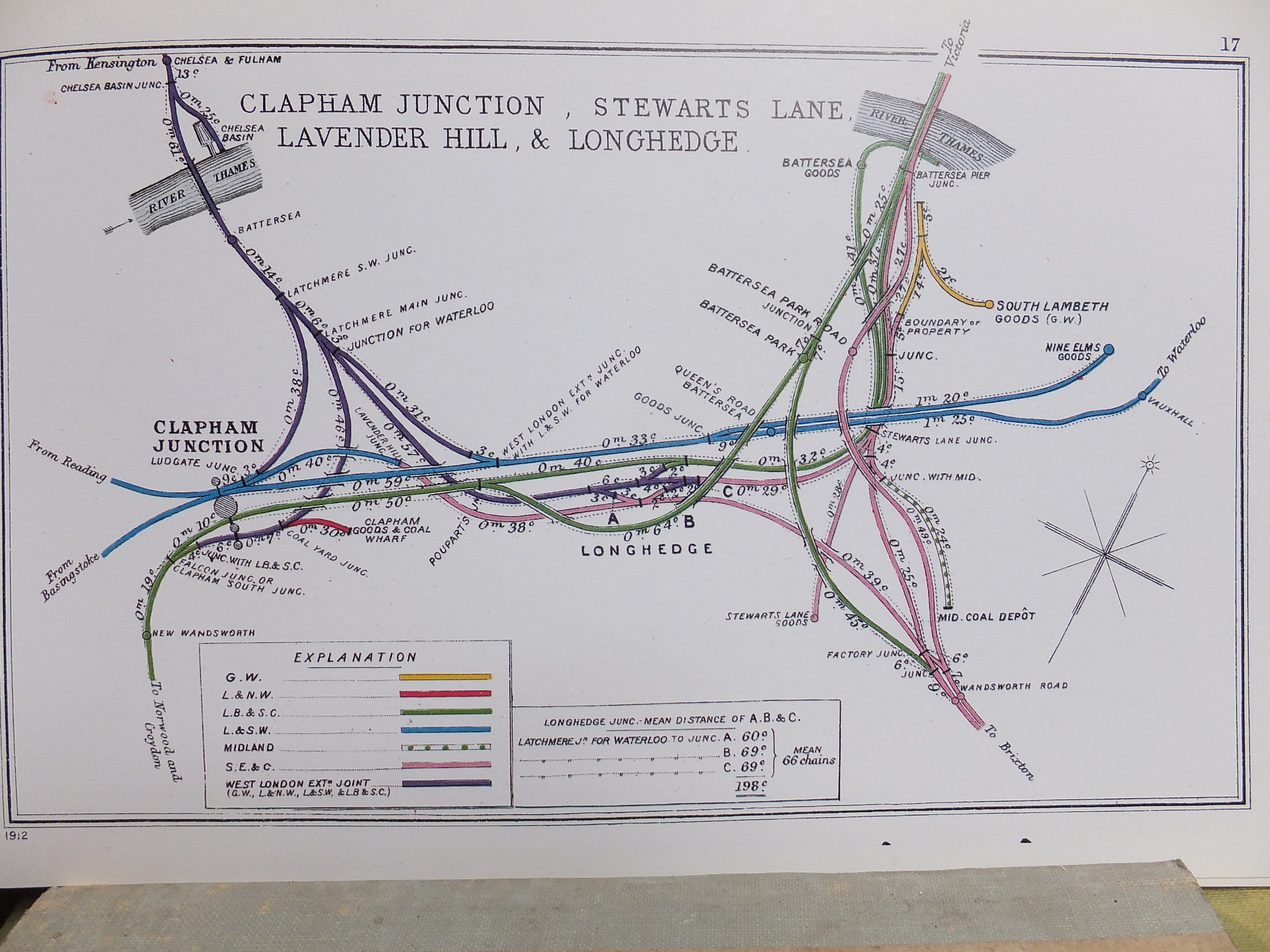
All the major stations in central London were termini, set in a 'ring' within which railways were prohibited until the advent of underground railways. This was inconvenient for those passengers whose destinations lay on the far side of London and railways desired the possibility of through working. The West London Railway connected major railways like the London and North Western Railway and the Great Western Railway with destinations on the north bank of the Thames in the west of London. The West London Extension Joint Railway (jointly owned by the London and North Western Railway, the Great Western Railway, the London and South Western Railway and the London Brighton and South Coast Railway) extended the West London Railway south across the Thames and then split into four branches which joined the London and South Western Railway (both eastbound and westbound) and the London Brighton and South Coast Railway (both eastbound and westbound). The diagram below shows the layout of the various lines at the time of the First World War.
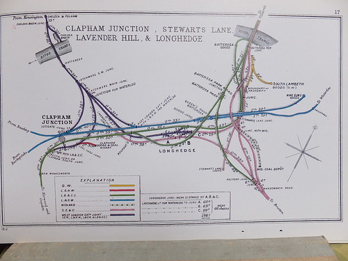 Click for larger image.
Details of the junctions between various railways in the vicinity of Clapham Junction. This diagram is one of a series prepared by the Railway Clearing House in 1914 which appear in the reprint 'Pre-Grouping Railway Junction Diagrams 1914', published by Ian Allen (ISBN 0 7110 1256 3).
The following railways appear on the diagram:-
Great Western Railway.Three goods yards, whilst owned by one railway, were only rail-accessible by using "Running Powers" over another railway, making the situation even more complicated:-
London & North Western Railway.
London Brighton and South Coast Railway.
London and South Western Railway.
Midland Railway.
South Eastern and Chatham Railway.
West London Extension Joint Railway.
Clapham Goods and Coal Wharf (London and North Western Railway).Years ago, I remember being puzzled, looking down on South Lambeth Goods from an electric multiple unit, seeing a 'Pannier' tank locomotive and a Great Western 'Parachute' water tank in the shadow of the huge warehouse building. I didn't know then that the Great Western had once been part owners of the Eastern Section of Victoria (which was originally dual gauge!) and that the secret behind these incursions of other railways was the West London Extension Joint Railway.
Midland Coal Depot (Midland Railway).
South Lambeth Goods (Great Western Railway).
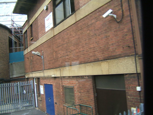
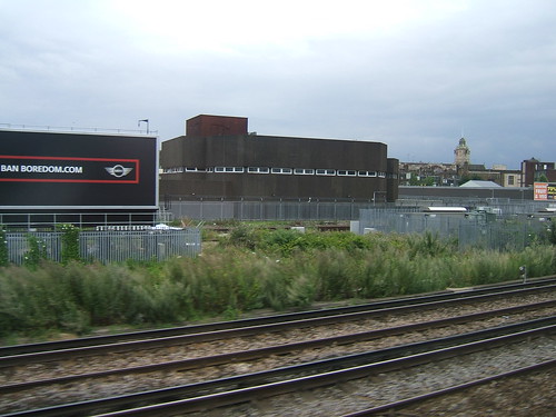 The sombre building in the background is the present Victoria Area Signalling Centre.
 Clapham Junction: View from west end of the 'South Western' side looking east, showing the largely un-modernised covered footbridge with a new lift-tower on the left.
 Clapham Junction: View from west end looking south, showing the less-ornate newer covered footbridge on the 'Brighton' side, with a new lift-tower. The main station building is in the background.
 Modernised platform access on the 'Brighton' side, with lots of glass.
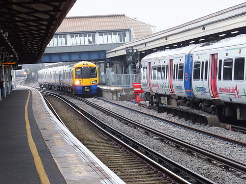 Clapham Junction: View from east end of platform 3 looking west with Overground train in platform 2 and Overground train (covered in 'official graffiti') in platform 1.

 Vauxhall Station, looking towards Waterloo.
 Click for larger image
 Battersea Park station, seen from a train on the Down Brighton Fast (platform 5).
Brought up in the Midlands in the early days of the post-war Nationalised railway, the former Southern Railway was very much a 'foreign railway' to me. It was some time before I started to discover some of the history of the lines in the south of the country.
Then and Now

The tower of the building designed by Albert Lakeman in 1939 for Imperial Airways is visible in both pictures. After the Second World War, Imperial Airways was nationalised and became part of British Overseas Airways Corporation. The building is now occupied by the National Audit Office.
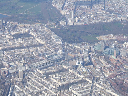
Victoria Station in a 2009 aerial view. The terminus is in the middle of the picture, with the approach tracks towards the lower left. The 'country end' of the station is virtually buried under modern developments. Hyde Park is top left, with Green Park and Buckingham Palace to the right. Centre right is Westminster Cathedral (Roman Catholic), designed in the late 19th century by John Francis Bentley in Early Christian Byzantine style.
Brief History
Whereas many of London's terminal stations served one railway company, Victoria ended up serving a number. The London Brighton and South Coast Railway, South Eastern Railway and the London and Chatham Railway initially terminated at London Bridge but co-operated in constructing a new route which crossed the Thames to terminate in what became Victoria Station. The London Brighton and South Coast Railway accomodated itself on the platforms on the western side. The eastern platforms were initially dual gauge and used by the Great Western Railway, the South Eastern Railway and the London and Chatham Railway. These last two railways worked together fairly closely, before amalgamating formally as the South Eastern and Chatham Railway. Traffic growth necessitated widening the Grosvenor Bridge over the River Thames to accommodate additional lines, producing a number of routes which criss-crossed one another south of the Thames, as shown in the 1914 map below.
Details of the junctions between various railways in the vicinity of Victoria. This diagram is one of a series prepared by the Railway Clearing House in 1914 which appear in the reprint 'Pre-Grouping Railway Junction Diagrams 1914', published by Ian Allen (ISBN 0 7110 1256 3).
The 1921 Railways Act created the 'Big Four' (L.M.S., G.W.R., L.N.E.R. and S.R.). The Southern Railway brought together the London Brighton and South Coast Railway, the South Eastern and Chatham Railway and the London and South Western Railway. Upon Nationalisation in 1948, the Southern Region of British Railways absorbed the assets of the Southern Railway. Even today, Victoria largely operates as two stations side-by-side - the Central Section dealing with the Brighton lines and the Eastern Section serving the Chatham lines.
Signalling
Before the Victoria Area Signalling Control was brought into use at Clapham Junction in 1980, Victoria was served by two power boxes. The Eastern Section had a separate signal box with a G.R.S. power frame. This lasted until 1979 when control passed for a short time to a temporary panel in the Victoria Central power box.
The Southern Railway had installed signalling power frames of Westinghouse Style 'K' at various locations. The Style 'K' retained mechanical interlocking between the miniature levers. The later Style 'L' 'All Electric' power frames introduced electrical interlocking between levers and the Southern Railway was an early adopter of the new design. In 1937, an order was placed for a 225-lever frame for Victoria Central with 51 point levers, 148 signal levers, 2 special levers and 24 spare levers. This was commissioned in June 1939 and continued in service until 1980. A temporary panel then took over until the new Victoria Area Signalling Control was brought into use at Clapham Junction.
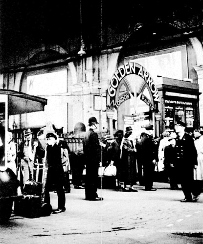 Ticket Barrier for the 'Golden Arrow' at Victoria in the 'Southern' era (Photo: VSOE).
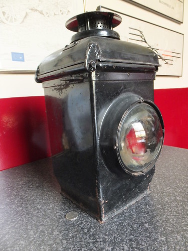
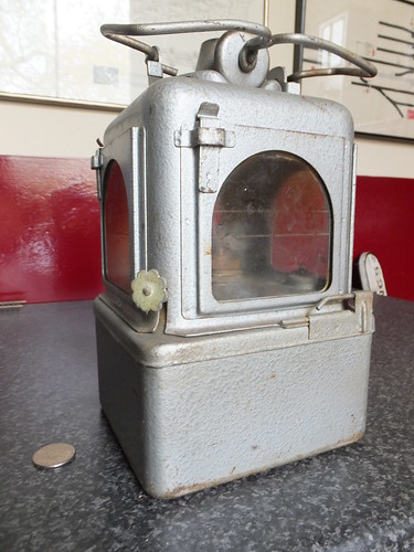
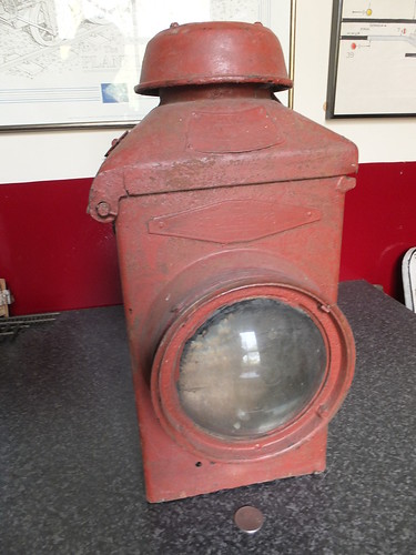
At night, the arm of a semaphore signal becomes invisible so the signal aspect is given by a signal lamp (usually paraffin) in front of which two coloured filter glasses connected to the signal arm are moved:-
'Stop' signals - Display either a RED or GREEN light. 'Distant' signals - Display either a YELLOW or GREEN light.The reliability of the lamp and its ability to continue burning in adverse weather conditions was paramount and considerable ingenuity was devoted to producing suitable designs. Care and cleanliness in the handling and maintenance of signal lamps was essential. 'Lamp Oil' was produced to a high and constant specification to ensure consistent performance. Reports of "Signal Lamp Out when should be lit" were treated with the utmost gravity.
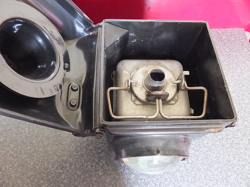 'ADLAKE' Lamp Housing, viewed from above with hinging top opened and removable lamp assembly in position. The fillet in the back left corner of the housing ensures correct alignment of the lamp assembly.

 Rear view of this type of lamp housing fitted to an upper quadrant tubular post signal. The signal lamp has a clear lens at the back, the 'back light'. The cast arm at 'six o'clock' with the curved screen is the 'Back Blinder'.
 View from above showing this type of lamp housing fitted to an upper quadrant lattice post signal, with the lamp housing open to show the lighted signal lamp inside. At the top of the picture can be seen the filter glasses producing the appropriate signal aspect.
 View other sizes.
I was brought up in the West Midlands in the early days of the post-war Nationalised railway so, although I was familiar with both the former L.M.S. and G.W.R. lines where I lived, the former Southern Railway was very much a 'foreign railway' to me. Around 1951 my mother and I visited Waterloo and other London termini during an extended trip (which even took us to Boulogne, described here). The 'Southern' electrics were very unfamiliar but there was plenty of steam to look at - particularly the 'air-smoothed' Bulleid 'Pacifics'.
 A Bulleid 'Pacific' leaving Waterloo (Photo: British Railways).
It was only many years later when I started to discover some of the history of the lines in the south of the country. Waterloo was the London terminus of the London and South Western Railway, which was well-regarded for its locomotives, less so for its passenger coaches and stations. In the 20th century, the London and South Western Railway rebuilt the nondescript Waterloo, producing a terminus which was much admired. The column-free concourse and the platforms were covered by an airy glazed roof and there was an impressive array of offices on the road side of the concourse.
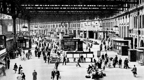 View across the Concourse at Waterloo in the 'Southern' era (Photo: British Railways).
I'm afraid I don't think the station has been much improved in recent years. The modern ticket barriers and retail outlets now encroach onto the platform side of the concourse which is further narrowed by the new mezzanine floor on the road side. Overhead, a bewildering array of suspended signage, CCTV cameras and loudspeakers destroys the original sense of space without easing the traveller's route through the clutter very much. Of course, it's all aimed at increasing the 'retail opportunities' offered to 'customers'.
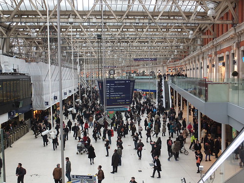 View across the Concourse from the mezzanine adjacent to platform 1 in 2013.
Post-War developments
Upon Nationalisation of the railways in 1948, the Southern Region of British Railways absorbed the assets of the Southern Railway. The Southern Railway had been created by the 1921 Railways Act which grouped railways into the 'Big Four' (L.M.S., G.W.R., L.N.E.R. and S.R.). The Southern Railway brought together the London Brighton and South Coast Railway, the South Eastern and Chatham Railway and the London and South Western Railway. Steam working was eliminated and third-rail electrification (started by the Southern Railway in the 1930s) was extended to more destinations. Perhaps the biggest change in recent years was the building of Waterloo International to handle the 'Eurostar' trains on the Channel Tunnel route. However, once our very-first High Speed Railway was completed to St. Pancras International (briefly described here), Waterloo International was abandoned and currently wears a forlorn air as Network Rail decide just how much money will be needed to convert the area for use by other trains.

A modern view of Waterloo Station (centre) with Hungerford Bridge leading to Charing Cross station towards the top. Although the station and rail approaches have been extended since first built, the way in which the line from Nine Elms was extended over arches is still apparent. The long platforms of Waterloo International (beyond the earlier train shed) served the 'Eurostar' trains until High Speed One diverted these trains to St. Pancras International.
 Click for larger image
Another aerial view of Waterloo.
Origins of Waterloo Station
The London and Southampton Railway was promoted as early as 1831 and a limited service started on 21st May 1838 between a London terminus at Nine Elms and Woking Common. As construction of the line towards Southampton continued, the name of the railway was changed to the more impressive-sounding 'London and South Western Railway'. A branch to Richmond was opened in 1846 but the growing traffic showed up the inadequacy of Nine Elms as a terminus. An extension was authorised from Nine Elms to a new station near the south end of Waterloo Bridge called 'Waterloo'. In 1848, Nine Elms was closed to the public (although retained for Royal Trains and goods) when all passenger traffic was diverted to Waterloo. The initial Waterloo Station had four platforms with two 'middle lines'. The L.S.W.R. intended to extend the line beyond Waterloo to get nearer to the City of London, which was the ultimate destination for many of its regular passengers. As a stop-gap, one of the 'middle lines' was extended to form a through connection with the South Eastern Railway (later to become the S.E.C.R.) but today there's only a pedestrian connection between the terminal platforms at Waterloo and the through platforms at Waterloo East. As an alternative, the L.S.W.R. supported the initiative to build an underground electric railway from Waterloo to the City. Initially, it operated the railway on behalf of the Waterloo and City company, but it later acquired ownership. There's a little more on the Waterloo & City Line in the article here or, for a detailed history of the Waterloo and City Line, see Book [3] below.
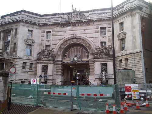 A modern view of the imposing main entrance for foot passengers provided by the L.S.W.R. at Waterloo. After the 'Great War' of 1914-1918, this entrance became the Memorial to L.S.W.R. staff lost in World War I. The view is rather spoilt by the 'temporary' works in the foreground.
Related posts on this web site
Visiting former 'Southern' stations in London (describes Waterloo East).
Waterloo Station, London (Part 2).
External web sites
London Waterloo Station (Wikipedia).
Waterloo (Network Rail).
My Pictures
Waterloo Station.
Books
[1] 'London's Termini' by Alan A. Jackson, published by David & Charles (0 330 02746 6). (The L.S.W.R. Terminus at Waterloo is described in Chapter 11).
[2] 'Railway Track Diagrams Book 5: Southern and TfL' Third Edition, published by TRACKmaps (ISBN 978-0-9549866-4-3).
[3] 'The Waterloo & City Railway by John C. Gillham, published by the Oakwood Press (ISBN 0 85361 544 6).
[9-May 2013: Second aerial photo added, reference to Book [3] added. 18-Sep-2015: 'Related posts' added.]
'Slotting' is a technique employed in semaphore signalling which gives two signal boxes control over one signal arm and was commonly used where signal boxes were close together.
Co-located Stop/Distant Signal Slotting
A frequent requirement for slotting occurred where a distant signal controlled by one signal box was mounted on the same post but below a stop signal controlled by the signal box in the rear. The 'slot' prevented the distant arm from coming 'off' until the stop signal arm above it was also 'off'.
The picture below shows the stop signal/distant signal slot on a Western Region pattern lower quadrant signal, with both signals 'on'. The weight bar nearest the camera (with two counterweights) is for the distant, the weight bar with the single counterweight is for the 'stop' signal. With no tension in the signal wires, the weightbars are held in the position shown by the counterweights. Two 'L' cranks at the bottom of the post transfer the horizontal 'pull' on the signal wires to a vertical 'pull' via two short signal wires to the ends of the two pivoted weightbars. A push-rod is attached to the stop signal weightbar, on the counterweight side of the pivot, so that, when the stop signal wire is pulled, the counterweight rises and the push rod is pushed upwards to move the signal arm to the 'off' position. A second push-rod is provided to operate the distant signal arm but this push rod is attached not to the distant weight bar, but to a third weight bar placed in between the other two. This third weight bar is provided with a smaller weight and it also has two projecting lugs which sit on top of the other two weight bars all on the other side of the pivot from the first two weightbars. With both signals 'on' the smaller weight on the third weightbar is lifted by the other two weightbars pushing up against the lugs. The weights are arranged so that if either the stop signal or distant signal wire is pulled, the remaining lug pushing up on the third weight bar keeps the smaller weight lifted.
 View other sizes.
View from front of signal with neither signal wire 'pulled' - both Stop and Distant signal arms 'On'.
The picture below (taken from the other side of the signal) shows the situation if both signal wires are pulled. The tension in the stop signal wire holds the counterweight lifted and the pushrod lifted upwards to move the stop signal arm to the 'off' position. The tension in the distant signal wire holds the two distant counterweights lifted. With neither of the two weightbars pushing on the lugs of the third weightbar, the smaller weight falls under gravity, pivoting the third weightbar and lifting the distant pushrod to move the distant signal arm to the 'off' position.
 View other sizes.
View from rear of signal with both signal wires 'pulled' - both Stop and Distant signal arms 'Off'.
Stop Signal Slotted by Two Signal Boxes
There were instances where it was considered unsafe for one signal box to have total control of a stop signal and co-operation between two adjacent boxes was enforced by clearing the signal only when both boxes had operated their 'slot' levers. The actual slotting mechanism at the signal was similar to that described above for Stop/Distant Signal Slotting.
Sedgeley Junction signal box had an example. If you look at the sketch signal box diagram in the post Sedgeley Junction (again) you can see that lever 35 'slotted' Dudley East's Down Starter. This was to provide protection for a train on the Down at Coneygree. This particular instance was a bit odd because the slot stood 'off' - you only pulled the lever when you wanted to ensure that Dudley East's Down Starter remained 'on' - the lever was 'normal' most of the time, giving Dudley East sole control of the signal.
The Up and Down Goods between Deepfields and Spring Vale was another example. My Deepfields signal box diagram in the post Railway signalling: Deepfields shows the slot on signal 38 (but omits the ones on 23, 28 and 29, although I did record the complexity of the stop/distant slotting on the down: to get Spring Vales's Distant signal mounted underneath the stop arm controlled by Deepfields lever 2 to show 'off', four weight bars had to be 'off' - one pulled by Spring Vale, one each pulled by Deepfields levers 2, 3 and 4). My signal box diagram of Spring Vale in the post Railway Signalling: Spring Vale Sidings Box does show the slots on Deepfields 23, 28 and 29.
Certainly in London and North Western Railway Signal Boxes, it was common to give the signalman an indication of whether the slot operated by the other box was 'off'. This was achieved by providing 'Face Disks' behind the frame, operated by signal wire. These normally sat horizontal but, when pulled vertical by the other box, displayed 'SLOT OFF'. The excellent book 'A Pictorial Record of L.N.W.R. Signalling' by Richard D. Foster, published by Oxford Publishing Company in 1982 (SBN: 86093 147 1) has more details.
Maintenance of this mechanical complexity must have been a problem and I think there was a policy of eliminating it where possible. I'm sure it's the sort of thing to appeal to A.F. Bound (the LMS Chief Signal and Telecommunications Engineer from 1929). Increasing provision of track circuits, Block Control and electric lever locks would provide justification in some instances for the elimination of mechanical slotting. Another technique was 'Distant Indicator Working' which is briefly described in section 8 of the post Railway Signalling: Tipton (Part 2) and I believe the signalmans' regulations applying where Distant Indicators were provided probably lessened the need for traditional slotting.
Go to Part 4 - Semaphore Signal Aspects by Night.
Part 1 described the evolution of fixed signals. After a long period of development, the 'modern' form of 2-aspect semaphore signalling emerged (but is now being rapidly eliminated by Network Rail).
Types of Fixed Signals
There are two principal classes of fixed signal:-
'Stop' signals - these are mandatory and an approaching driver must stop if the signal displays a 'stop' aspect.Signals comprise a vertical post (of wood, steel tube, steel lattice or occasionally reinforced concrete) on which is mounted one or more 'stop' or 'distant' signal arms each comprising a rectangular 'blade' (of wood or steel) mounted on a pivot so as to extend to the left of the signal post (viewed from an approaching train to which the signal applies) at a height to facilitate observation by the driver of an approaching train.
'Distant' signals - these are warning and an approaching driver may pass the signal displaying a caution or restrictive aspect but be prepared to stop at the following 'stop' signal.
'Stop' signals - Arm is square-ended. Front of arm is RED with a WHITE vertical band near the end, rear is WHITE with a BLACK vertical band near the end.The two types of signal are distinguished by night by providing a lamp (usually paraffin), in front of which two coloured filter glasses connected to the signal arm are moved:-
View other sizes.
Upper quadrant 'Stop' signal displaying 'STOP' indication (Shackerstone Outer Home).
'Distant' signals - Arm is 'V'-ended. Front of arm is YELLOW with a BLACK chevron near the end, rear is WHITE with a BLACK chevron near the end.
View other sizes.
Darley Dale Down (fixed) Distant Signal. The black and white painting of the post indicates an 'Independent' Distant - one not co-located with a 'Stop' Signal.
'Stop' signals - Display either a RED or GREEN light.Aspects
'Distant' signals - Display either a YELLOW or GREEN light.
Arm is horizontal ('ON' Aspect): 'STOP' (if a stop signal), 'Proceed with Caution' (if a distant signal).If the arm is raised by 45 degrees to indicate 'PROCEED', signal is termed 'UPPER QUADRANT' or, if lowered by 45 degrees to indicate 'PROCEED', signal is termed 'LOWER QUADRANT'.
At night, the indications are Red light: 'STOP'(if a stop signal), Yellow light: 'Proceed with Caution' (if a distant signal).
Arm is raised or lowered by 45 degrees ('OFF' Aspect): 'PROCEED'.
At night, the indications are Green light: 'PROCEED'.
 An elderly Great Western signal. The signal arms are wooden, as is the 'doll' (vertical post) mounting the arms. The lower arm is smaller and the 'S' indicates that it authorises a shunting movement past the signal.
 View other sizes.
 View other sizes.
 View other sizes.
 View other sizes.
 View other sizes.
 View other sizes.


