Sunday, 11 September 2016

Locomotive Regulators (part 2)

Click on any picture or drawing below for a larger, uncropped view.

In the article Locomotive Regulators (part 1) I discussed early regulators for steam locomotives and the very common two-port slide valve designs.

Whatever the precise design, this steam valve, which allows the engine to move, is called the 'Regulator' or sometimes the 'Throttle'. It's a proportionate valve - the more the operating handle is moved, the more steam flows to the cylinders. The valve itself is usually mounted within the boiler, where the steam is generated, as part of the 'steam dome'. The steam dome is the highest part of the boiler to minimise the pick-up of droplets of water from the mass of water below. Alternately, the regulator valve could be situated in the smokebox - the Great Western developed a very successful smokebox regulator of the horizontal slide valve type.

Conventionally, the regulator is controlled by rotating the regulator rod passing through the boiler backhead so as to operate the regulator mechanism in the boiler. This rotation is achieved by pulling on what may be a fairly long handle attached to the end of the regulator rod on the footplate to give the driver sufficient leverage to be able to adjust the regulator valve against the pressure of steam inside the boiler. In the most common designs, the driver moves this handle in an arc. In 'Lion', for instance, it's fully closed with the handle at about 2 o'clock and fully open at about 10 o'clock. Different classes of engine have different detailed regulator design and sweep through different arcs. For instance, most Great Western Engines have a regulator handle which moves from 5 o'clock to 1 o'clock. I was surprised to discover that the regulator on the marvellous Great Eastern '1500' class moves from 4 o'clock to 8 o'clock ('underarm'). Left hand drive engines have mirror-image regulator arcs.

The steam pressure on the valves in the slide valve pattern helps to stop steam leaking past the valve but, as boiler pressures became higher and locomotives became more powerful, regulators could be quite hard to open or shut, sometimes needing the combined efforts of driver and fireman so some designs have two handles attached to one regulator rod - one, conventionally, pointing towards the driver's position, the second pointing to the fireman's side. The effort required, particularly to open a regulator onto 'Main Valve' (also called 'Second valve') can be quite demanding.

On smaller locomotives, a second regulator handle may be fitted because, during shunting, the driver may have a better view from the 'wrong' side of the cab and the second handle allows the driver better control of the movement. Some designs also provided a duplicate brake valve on the 'wrong' side. Where small shunting locomotives were used in private sidings, 'single manning' was often resorted to so the distinction between 'Driver' and 'Fireman' was lost.

Not all regulator handles would stay where they were put, but would tend to 'creep'. To counter this, enginemen might carry a wedge which could be placed between the regulator handle and the quadrant to prevent unwanted movement. In India, I found a chain used to prevent the regulator from creeping closed.

Many Overseas, L.N.E.R., S.R. and British Rail 'Standard' locomotives had 'pull-out' regulator handles moving fore-and-aft where the handle is pulled towards the driver to admit steam to the cylinders often, but not invariably, working a 'balanced' regulator. On Overseas locomotives with this feature, there is often a ratchet mechanism, released by a trigger handle, to prevent the regulator from 'creeping' from the set position, but I've not seen this feature on British-made engines used in Britain.

Plug and Butterfly designs (mentioned in part 1) were, as far as I know, only used in the early years of locomotive design so now we have just slide valve, balanced and multi-valve (as used, for instance, on LMS 'Pacifics') types to consider.

Vertical Dome-mounted Slide-valve regulators

The arrangement of this type of regulator was shown in part 1 of this post and the picture below shows a vertical slide valve regulator on the sectioned locomotive 'Pender' at the Museum of Science and Industry in Manchester (MOSI), where I was a Volunteer for many years (resulting in a number of posts about MOSI here).


There are also a couple of pictures in the post The Best Laid Schemes ... which describes the failure of a regulator linkage.

Horizontal Dome-mounted Slide-valve regulators

As boilers became larger, vertical dome-mounted regulator valves could be hard to fit within the loading gauge. At the L.M.S. Stanier, with his Swindon background, originally adopted the Great Western approach of a slide-valve regulator mounted in the smokebox but, with the introduction of his 4-6-0s, he produced a dome-mounted horizontal slide valve regulator which most enginemen liked.

In the diagram below, 14 is the port face forming the start of the main stam pipe which has with three ports, covered by the main valve 8 when the regulator is shut. The main valve 8 is provided with two narrow openings 6 and 7 which are normally open to steam and two main ports 11a and 12a each divided into three which are closed to steam until the main valve 8 is displaced from the closed position. The pilot valve 5, when closed, obstructs the narrow openings 6 and 7 in the main valve but does not impede steam through main ports 11a and 12a. To open the regulator, the regulator rod is rotated, pivoting the actuating rod 3 which moves the actuating rod 4, forcing the pilot valve to move, successively opening narrow openings 6 and 7 so that steam flows from the dome to the main steam pipe. The actuating slot in the top of the main valve is wide, so that the actuating rod 4 does not start to move the main valve until pilot ports 6 and 7 are fully open, then main ports 11a and 12a allowing increased steam flow.


Balanced 'Double-beat' regulators

To reduce the effort required by the driver in making adjustments to the regulator, the balanced, or 'double-beat' regulator was introduced. An early form was produced by Ramsbottom. Later, Lockyer patented a version used by the North Eastern Railway. In the form used by Gresley,the balanced regulator allows steam on both sides of a lifting bobbin-shaped valve so reducing effort required to adjust the valve. The horizontal regulator rod (pushing from the right of the diagram below) operates the bell crank so as to lift the valve from its seating, allowing steam to flow from the dome to the main steam pipe.


'Flying Scotsman' has this type of valve. My post 'Flying Scotsman' has a contemporary drawing here. If you select one of the the larger sizes of the drawing, you can see how the balanced regulator is fitted into the boiler. The LNER (always masters of self-publicity) described the regulator as giving 'finger tip control'. Whenever I've driven 'Flying Scotsman', I've found the regulator provides nothing that could be remotely described as giving 'finger tip control'. There's a brief description of my early meetings with the locomotive here. The only 'A4' Pacific I've driven ('Sir Nigel Gresley), whilst otherwise a superb machine, was just as bad as far as ease-of-operation of the regulator goes.

Multiple Valve regulators

As far as I know, these were only used on large, superheated locomotives. A number of satisfactory designs of superheater were developed but The Superheater Company Limited achieved widespread success, marketing products under its 'MeLeSco' trade mark worldwide. It also developed a multiple valve regulator, which I think was used by the L.M.S. and L.N.E.R. and achieved worldwide sales well in excess of 40,000 units! The design (shown in the diagram below) is based on a modified superheater header casting where the forward part of the casting is divided into three transverse chambers, one above the other. The top chamber is connected to the superheated steam output from the superheater. The middle chamber connects to the main steam pipes, delivering superheated steam to the cylinder steam chest. The bottom chamber is a balancing chamber. A series of fairly small valves control the passage of steam from the top to middle chamber. These valves are progressively opened and closed by cams on a rotating camshaft operated by the regulator handle. Initial movement of the regulator handle first opens a pilot valve which admits steam to the balancing chamber so that further movement of the regulator requires little effort to open, in turn, each of the main valves.


I drove Princess Margaret Rose on one of her visits to Tyseley years ago but don't recall how I liked the regulator action using a multiple valve regulator - my impression was of a magnificent (and big) engine.

A Regulator Gallery

I like the Great Western regulators which I've experienced on a number of classes. The regulator on 5080 'Defiant' really was 'finger-tip' - I'm sad that she's now on static display at Buckinghamshire Railway Centre.


Standard Great Western regulator handle on 2-8-0 '3803'. Note the round counterweight.


Stanier regulator handle on 2-8-0 '8624'. Note the sprung stop bearing on the quadrant, preventing 'creep'.

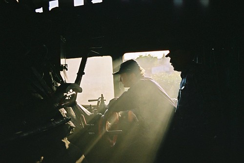
In 1992, I had an opportunity to drive a Class 'WP' on the main line in India. There's a brief description of this trip buried in the post here.


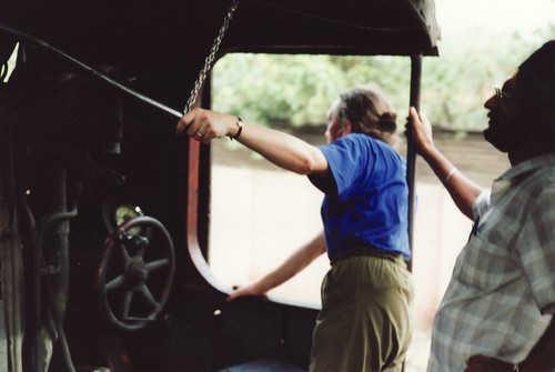
Class 'WP' in India: I'm holding the regulator handle through force of habit - at this point, we've attached a chain from the roof to the handle to prevent the regulator from closing itself.

The only American-built class I've driven is an 'S160' (with a ratcheted regulator handle) at Peak Rail. On tugging open the regulator, there was a distinct delay, followed by a 'clang' from the dome (which, at the time, I commented "sounded like a dustbin lid being rattled"), then steam flowed.

The spartan lines of an 'S160' (Photo: lner.info)

In 2003, I was fortunate in driving three different locomotive classes at Wolsztyn in Poland. There's a post called, simply, Poland with a link to pictures.

Pm36-2 'Piekna Helena' en route to Lesno (the 'arty' shot). The regulator arc is from about 1 o'clock to 11 o'clock.

In 2005, I had the opportunity to drive three Russian-designed classes in Ukraine - the first of a series of posts is at Ukraine 2005 with links to pictures.


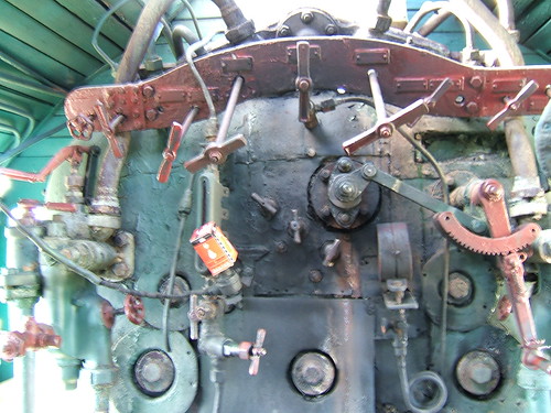
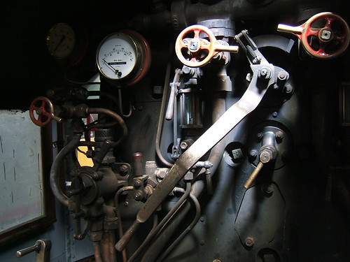
Russian-designed Su 251-86 in Ukraine showing boiler backhead with short regulator handle (with ratchet) rotating the regulator rod via a link.

Friday, 9 September 2016

The Mergui Archipelago (day 6)

Events of Thursday, 28th April, 2016

In the post on the previous day's activities, here I described how the smaller fishing vessels clustered overnight around Bar Wel Island. On Thursday morning, by the time we were enjoying our accustomed sustaining breakfast on deck, many of these boats had either already left for a day's fishing or were preparing to go out. But quite a few of the odd-looking squid fishing vessels remained, probably having returned after a night's fishing.

Squid fishing is usually carried out at night, assisted by numerous powerful electric lamps (mercury vapour Lamps, producing a rather eerie blue light). These lamps are arrayed along a series of improbably long booms extended horizontally out from the hull. No two vessels seem alike in the details of the rigging of the booms, although they generally appeared to be converted from fairly elderly 'trawler' types, similar in layout to the one we'd visited earlier in our cruise (described here), having a stayed derrick mast (either wood or steel) on the foredeck with a single boom to unload the catch and load supplies. Usually, the booms were made of what appeared to be a series of substantial steel tubes joined together with couplers to produce the required length but I also saw trusses made from smaller tubes with welded cross-bracing. The booms require a complex series of guy ropes to support them and these ropes terminate on the derrick mast on the foredeck and on a smaller stern derrick or on the superstructure.


The fishing fleet at Ba Wel: A stern view shows the length of the steel lighting booms, which are supported by guying from a steel derrick mast on the foredeck and a smaller steel mast at the stern.


The fishing fleet at Ba Wel: This Squid Fisher has a wooden Derrick mast and both tubular and truss booms to support the lamps.

Squid are an important food source in many parts of the world. There's an introduction to the creature here. There's a little about fishing for shortfin squid here. The lighting system attracts the nocturnal squid to the fishing vessel, gathering in the unlit area beneath the hull, waiting for prey. A series of lines, carrying metal 'lures', are lowered into the water and 'jigged' up and down, encouraging the squid to attack the lures, in which they become entangled. Periodically, the lines are raised to recover the catch. Modern Squid Fishing vessels are equipped with Jigging Manchines which lower the lines, 'jig' them, raise the lines and invert the lures so that the squid fall off automatically (as outlined here) but I saw no evidence of this type of equipment in use at Ba Wel.


A Squid fishing vessel under way (pictured on a previous day).


A rather ungainly-looking squid fishing vessel at Ba Wel Island (pictured on a previous day). Six men can be seen, plus, I assume, one in the wheelhouse.

After enjoying the usual sustaining breakfast, we made our return to Kawthaung under engine power: our final opportunity to enjoy simply being at sea. After a few days around the undeveloped islands, the sheer size and the bustle around Kawthaung came as something of a shock.


Arriving back at Kawthaung.

'Meta IV' anchored in the harbour and all the guests said 'Goodbye' to the crew. We piled into the dinghy with our luggage and Aung transferred us to Myoma Jetty. My Australian friends and I were booked on the afternoon flight back to Yangon, so, once Aung had retrieved the car, he drove us towards the airport. It took me a while to adjust to the level of road traffic, much of it motor cycle taxis of a distinctive design, apparently quite modern but with the driver on the right of the machine, more suited to driving on the left of the road (as Burma did, until the sudden change to driving on the right mandated in 1970).


Around Kawthaung.

As our flight did not leave for a few hours, Aung had arranged for us to relax in the luxury of the Victoria Cliff Hotel & Resort. After a light lunch in the restaurant which offered stunning views of the Andaman Sea, I relaxed in the shade by the swimming pool. It was very hot, and I couldn't muster the energy for anything requiring more exertion.


Around Kawthaung: The swimming pool at the Victoria Cliff Hotel & Resort.

Aung picked us up in plenty of time for the final road journey to Kawthaung Airport, where we left Aung. I'm afraid that, after the comfort at the Victoria Cliff, Kawthaung Airport was rather basic but, eventually, our flight arrived and I boarded with some relief.


Kawthaung-Dawei-Yangon by air: Boarding the Apex flight to Yangon

On the way back to Yangon, we made the scheduled brief stop at Dawei, arriving at the Domestic Terminal at Mingalardon on time. My checked bag appeared fairly quickly, my transport was waiting and I was soon returned to the Doctor's house, where I was staying the night. The next morning I had another early start, as I was to fly north with the Doctor to Bagan.

Related posts

Next post in this series.

All my posts on my trip to Myanmar in 2016 can be found here.

My pictures

If necessary, pictures in this article can be viewed uncropped by clicking on the image. To view in other resolutions or download, select from the albums below:-

The Fishing Fleet at Ba Wel.
Sailing back to Kawthaung.
Around Kawthaung.
Kawthaung - Dawei - Yangon by air.
All my pictures on this trip.

Monday, 5 September 2016

'Lionsmeet' 2016

Every year, the Old Locomotive Committee (OLCO) organises a get-together, called 'Lionsmeet' for modellers of the 'Lion' locomotive (and similar models of designs from the early days of railways). On Saturday 27th August 2016, I attended the Old Locomotive Committee annual 'Lionsmeet' event which was held at the Nottingham Society of Model and Experimental Engineers Limited (Nottingham SMEE) site at Ruddington, occupying part of what was formerly called Nottingham Transport Heritage Centre.

Getting there

I travelled by train from Wolverhampton and there's a post describing the journey here. After doing a quick survey of the station and its architecture, I took a taxi from Nottingham Station. As we drove through the city, it started to rain and then the driver had some difficulty locating the destination because the post code which had been advised was not the best one and left us, tantalisingly, a few hundred yards short of my goal. Fortunately, I spotted a brown 'tourist sign' in the distance and was able to direct the local driver the rest of the way! I afterwards discovered that a more helpful post code would have been NG11 6JS. We'd arrived at the large site, apparently originally an industrial complex. Part of the area had been redeveloped as modern commercial property whilst the remainder now provided accommodation not only for Nottingham SMEE, a preserved bus group and a model railway group but also serves as headquarters for the standard gauge-preserved railway Great Central Railway - Nottingham. Just inside the main gate I spotted a large sign directing visitors to the miniature railway so a few minutes trudge through the rain past the Bus Museum took me to my destination.

The Event

I found Andrew and David Neish in the Clubroom, sheltering from the rain and enjoying a warm drink. Soon, I'd also been provided with a beverage and the rain stopped, so things were looking far more promising. Activities transferred to the Steaming Bays as other attendees started to arrive by car.

Nottingham SMEE was first established in 1929 and has been on the present site for around 25 years. The original accommodation is a converted and extended industrial building providing a well-equipped workshop (including multiple Bridgeport manual milling machines), mess, kitchen, toilets and a spacious Clubroom with modern Audio-Visual facilities.


Nottingham SMEE: General view of the well-equipped workshop.

There is substantial purpose-built accommodation for 7.25" gauge locomotives and rolling stock. In one building, I admired a handsome 7.25" gauge model of a '2P' which was undergoing a boiler test.


Lionsmeet 2016, Nottingham: 40602 undergoing a hydraulic test. Boiler Inspector John Lopez underneath checking the firebox foundation ring.

There are custom-built covered Steaming Bays for 3.5" and 5" gauges.


Lionsmeet 2016, Nottingham SMEE: The Steaming Bays have three parallel raised tracks in a handsome building, topped by magnificent smoke louvres.

The original running track is 2270 feet in length, elevated, dumb-bell shaped, offering dual-gauge (3.5"/5") track using aluminium rails. There is now also an extensive 7.25" ground level system, roughly oval-shaped laid outside the elevated track. The 7.25" track also has a triangular junction serving a branch leading to a terminus called Parkgate nearer the site entrance .

As at recent 'Lionsmeet' events, the format was 'free running', that is no competitive running, using only the elevated track since no 7.25" gauge models steamed this year. As the 'early steamers' (notably Andrew and David Neish with David's familiar 'Lion' and Adrian Banks with his 'Thunderbolt') moved their models onto the elevated running track, I obtained permission to walk around the circuit to familiarise myself with the facilities.

The elevated track is signalled with automatic 3-aspect colour-light signals for clockwise running, so I took this direction for my walk, starting at Little Ruddington station.


Nottingham SMEE: Little Ruddington Station with (L-R) elevated track, 7.25" gauge station, exhibits outside Bus Museum.

Immediately on leaving the station, there is the expected traverser to move locomotives from the steaming bays towards the running circuit but this involves crossing the ground-level 7.25" track. This hazard is protected by a proper level crossing with four gates with gate stops, power-operated from the adjacent signal box, Little Ruddington West, and interlocked with signals on the ground level track.


Traverser serving the steaming bays pictured next to the level crossing.

The height of the Traverser can be adjusted as necessary. The Traverser mounts a battery to power the height adjustment and the battery can be re-charged from a power lead mounted on one of the steaming bay roof supporting columns. This traverser does not deliver locomotives directly to the running line but to an intermediate siding.

Next, I passed Little Ruddington West signal box which has a beautifully-engineered 50-lever frame in miniature which controls the power-operated points and signals on the ground-level track. This frame has a miniature level crossing gate wheel to control the level crossing gates and this requires around 12 turns in the appropriate direction before movement of the gates takes place!


Nottingham SMEE: Part of the miniature lever frame in Little Ruddington West signal box. Just visible left is the supporting frame carrying the level crossing gate wheel.

Just outside the signal box, a second traverser not only transfers locomotives from the intermediate siding to the elevated running line but also moves carriages between the carriage shed and the running line.


David Neish moving his 'Lion' onto the running line using the long traverser which also transfers carriages from the brick carriage shed visible in the background to the running line.

After this second traverser, the line then passes through a wooded area as it negotiates one end of the 'dumb bell'. The curvature and, on my visit, the dampness combined with 'leaves in the line' made this a tricky area for drivers.


Nottingham SMEE: The 'wooded area'.

Emerging from the wooded area, the elevated track passes a garden area which includes an extensive 'Gauge 1' layout on an raised baseboard. The elevated track then runs to the rear of the signal box and, on a long 'back straight', passes the station area.


A Nottingham SMEE member undertakes permanent way maintenance (or prayer?) as Adrian Banks heads for the tunnel on 'Thunderbolt'.


Nottingham SMEE: The rail joints in the 3.5" and 5" gauge track are 'lapped' to allow expansion of the aluminium rail.

The elevated track next passes through the first 'bore' of a '2-bore' tunnel before reversing direction on the second 'dumb bell'. After traversing the second 'bore' of the tunnel the line arrives back at the station area.


Nottingham SMEE: The tunnel section, looking towards the station.

A couple of diesel-outline petrol-engined models - a 2-car Diesel Multiple Unit and a 'Class 20' - gave rides to the public on the 7.25" gauge track.

Sophie, a lady engineer who is a member of Nottingham SMEE, ran her 'Lion' on the elevated track. Her 'Lion' is one of three built some years ago by Robert Clark, who was a respected member of Nottingham SMEE. Having sold one of the three (probably for display), the builder died when still quite young. The brother of the deceased gifted the second 'Lion' to a close friend of the builder. The remaining 'Lion' was offered to members of Nottingham SMEE and it was acquired by Sophie, who already had a number of loco building projects to her credit.


Lionsmeet 2016, Nottingham: Sophie and her friend.

By this time, Jon Swindlehurst with his 'Lion' and a fifth 'Lion' were being prepared for demonstration running.


Lionsmeet 2016, Nottingham: Jon Swindlehurst prepares his 'Lion' with another 'Lion' being steamed in the background.

I took one ride behind Jon (forgetting, despite years of being 'Official Observer' or 'Dynamometrix' during 'Lionsmeet' contests, what a 'fire thrower' his willing model can be - a real "Nor' Wessie" engine!) Demonstration running was suspended when a wide range of sandwiches was revealed for the visitors but after a leisurely break, some models continued to steam whilst other attendees either continued to chat or examined the part-built models on display.

John Hawley showed his part-built 7.25" gauge 'Lion' and the assembled driving wheelset for his 5" gauge 'Lion'. I foolishly originally described the as for his 7.25" 'Lion', forgetting that John had displayed his 5" 'Lion', started by Michael Lee, at the Guildford 'Lionsmeet' in 2015 (described here), when the driving wheelset was a 'kit of parts'.

Lionsmeet 2016, Nottingham: Part-assembled driving wheelset for John Hawley's 5" gauge 'Lion'.

Jon Swindlehurst showed progress on his remarkable 7.25" gauge 'Modified Lion', with Stephenson Link Motion and Balanced Slide Valves. Fabrications have replaced what would normally be castings.

Lionsmeet 2016, Nottingham: Jon Swindlehurst's 'Modified Lion' - view from above showing expansions links and valve rods.

OLCO member David Wilson displayed a modified design of regulator suitable for 'Lion' models. Chairman John Brandrick told me that it is based on the screw-down version described by Martin Evans for 'Simplex' and that Jon Swindlehurst's 'Lion' employs a similar design, not unlike that in the full-size Lion. There's a little about the regulators employed on full-size locomotives, including 'Lion', here.

Lionsmeet 2016, Nottingham: An OLCO Member displayed this modified design of regulator.

The rain had held off during most of the day the day and there were some periods of bright sunshine allowing everybody to enjoy the event.

Related posts on other sites

Lion & The Old Locomotive Committee
The Official Website for Lion & The Old Locomotive Committee.
The Nottingham Society of Model and Experimental Engineers Ltd.
Great Central Railway - Nottingham.


Related posts on this site

By Rail to Nottingham.
All my Old Locomotive Committee posts.

My pictures

Lionsmeet 2016.
All my Old Locomotive Committee pictures.

[Corrected following correspondence with J. Brandrick and J. Hawley: 9-Oct-2016]

Friday, 2 September 2016

By Rail to Nottingham

On Saturday 27th August 2016, I attended the Old Locomotive Committee annual 'Lionsmeet' event at the Nottingham Society of Model and Experimental Engineers Limited site at Ruddington Fields Station. I was the only passenger on the first bus from Brewood to Wolverhampton which currently leaves at 07:04 on Saturdays. A short walk took me to the station where I successfully purchased a ticket (from the second machine I tried). We do still have the luxury of a manned ticket office but this usually entails queueing. The public address advised that the next train to Birmingham had been cancelled "because of disruptive passengers at Telford" but I only had a few minutes to wait before a Virgin 'Pendolino' service left.


A quiet moment at Wolverhampton Station: View from platform 3 looking towards Birmingham with the redundant Power Signal Box on the left.

From Wolverhampton to Dudleyport, we were under the care of the West Midlands Signalling Centre at Saltley (control code BW) running under modern LED (light Emitting Diode) colour light signals. Then Birmingham New Street Power Signal Box took over and the signals were mainly Westinghouse 4-aspect colour lights dating from the 1960s. At Birmingham New Street, the 'Pendolino' stopped at platform 1. I discovered how poor the signage and lighting of the recently-rebuilt station is in places. To reach platform 7b for the Nottingham service I had to leave through the automatic ticket barrier and re-enter by another ticket barrier elsewhere, presumably because I took the nearest stairs from the platform marked 'Exit' (as, I think, many passengers might). I've written previously about being generally underwhelmed by the rebuilding here.


Grand Central, Birmingham New Street: One of a number of automatic 'Gate Lines' controlling entry and exit.

The 2-coach 'Class 170' for Nottingham was standing in the south end of platform 7, already well-loaded and we departed on time at 08:17.


1910 map of lines around Birmingham.
Click here for larger image.


Beyond Proof House Junction, shortly after leaving New Street, we passed from Birmingham New Street Power Signal Box's control to the more-modern West Midlands Signalling Centre's control area 'WP' (Water Orton-Proof House) with modern LED colour light signals. Just before passing the futuristic West Midlands Signalling Centre building, we passed Saltley Power Signal Box (dating from the 1960s) which no longer controls the Birmingham - Derby line although it retains control from Kings Norton to Barnt Green. Saltley Power Signal Box was one of three commissioned in 1969 which used a reed signalling system. The other two installations were Derby and Trent. Derby Power Signal Box currently remains in use but Trent Power Signal Box closed completely in 2013.


Birmingham to Derby: West Midlands Signalling Centre. The LED signal controls exit from the Freightliner Terminal to the Up Washwood Heath Goods Loop and other routes.

At Water Orton, signalling control passed to control area 'WW' (Wichnor-Water Orton), also within the West Midlands Signalling Centre. After a brief stop at Tamworth High Level, where we picked up quite a few passengers, signalling control then transferred to Derby Power Signal Box.

If, like me, you're interested in the operation of the railway itself, modern trains give rather restricted vision of the outside world. Some seats are not even aligned with a window or offer only a narrow, oblique view (certain seats on the 'Class 170' are culprits) and opening windows are a thing of the past. Audible cues can be helpful in interpreting what's going on. For instance, on this journey when the two-tone horn sounded followed after a few seconds by a single short horn, this suggested that the driver had spotted and warned a track worker ahead, the worker had moved to a place of safety and raised his arm in acknowledgement of the approaching train with the final horn confirming that the driver had seen the acknowledgement. On this occasion, the interpretation was confirmed as correct as I spotted the bright orange High-Visibility clothing of the track worker as we sped past the work site.

After a brief station stop at Burton-on-Trent, we accelerated away, passing the intriguingly-named Nemesis Rail depot. Then, there was a prolonged blast from the horn followed by fairly harsh braking. My guess was trespass on the line. We came to a stop just before signal DY187, which was 'green'. We stood for a few minutes, I imagined whilst the driver contacted the Signaller, then we continued to Derby. I couldn't confirm my interpretation of what had happened until we arrived at Nottingham but, yes, I was told the driver had seen "two youths walking down the cess" (the cess is the area immediately adjacent to a running line). The picture below shows the signal where we stopped and the design of this 4-aspect colour light is typical of the 1960s.


Birmingham to Derby: Starting away from an unscheduled stop at DY187 due to trespassers on the line.

The platform carrying the signal head is cantilevered to the right of the main post to improve sighting from a distance. For the benefit of the Signal and Telegraph Lineman, a simple handrail is provided around the platform and there is a permanent access ladder. The main post carries an identification plate with the unique signal number (usually first and last letters of the name, here 'DY' for 'Derby' and a number up to 3 digits long). This signal is on plain line with no diverging routes so the signal is arranged to operate automatically, as track circuits become occupied or cleared by the passage of trains. The white top part of the identification plate with a black horizontal bar indicates that this signal is not controlled by the signaller but is an 'Automatic'. However, a telephone is mounted lower down the main post which communicates with the Signaller. The two grey metal cabinets in the foreground are 'Location Cases' containing the necessary signalling relays, cable termination and power supplies. Two loudspeakers are mounted on the top of the smaller location case. This was the, rather crude, 'Staff Location System' of the period. Mobile phones, as we now understand them, were not available in the 1960s (1973 is accepted as the date of the first call on a Motorola mobile phone). Instead, the signaller could send one of four distinctive tones (one for each of three engineering disciplines plus a continuous tone for 'cancel) to the loudspeakers in an area where staff might be. As you can imagine, in built-up areas at night, use of this facility was not very popular with the neighbours.

In this type of colour light signal, four filamentary lamps are mounted vertically in line. When lit, each produces 'white' light (with a 'yellow' tinge). Colour filters in front of each lamp provide red, yellow or green light which is concentrated by a lens system on each lamp to project an intense beam towards the approaching trains when the lamp is lit. From the bottom, the four lamps produce red, yellow, green and, at the top, a second yellow. Four different 'aspects' or indications are given - red, yellow, green or 'double yellow' (where both yellow lamps are illuminated, but separated by the unlit 'green'aspect so that the driver can distinguish between 'single yellow - "prepare to stop at next signal" and 'double yellow' - "prepare to stop at next-but-one signal").

The most common repair would be 'replace failed lamp' but this type of lamp normally had two filaments. Failure of the main filament was detected by a lamp proving relay measuring the current flowing through the filament. Release of this relay upon failure of the main filament switched in the standby filament to keep the signal lit. The failure would be indicated to the Signaller (who, in the 1960s was still called a 'signalman') allowing the lineman to be alerted. Should the second filament fail or the power supply to the signal be lost, the signal would go 'dark'. In this case, the next signal in the rear would automatically be held at 'red' until relays proved that the failed signal should be showing a 'proceed' indication, in which case the signal in the rear would be allowed to display a 'single yellow' to allow trains to be kept moving whilst the problem was rectified. There's a little more information about this type of signal and the electromechanical relay circuits which typically controlled them here

We arrived at Derby on time, where the driver usually changes ends so as to depart on the Up Nottingham line. I say 'usually' because, on this particular diagram, we had a new driver from Derby to Nottingham.


Railway Clearing House Map: Derby, 1913.
Click here for larger image.


Of course, I remember Derby in steam days with mechanical signalling. At the south end of the platforms, a footbridge crossed the lines to the Works and, sometimes, this would be crowded with 'train spotters'. But my eye was always drawn to the nearby Midland-pattern signal box at London Road Junction.


London Road Junction signal box, Derby (Photo: The Derby Signalling Web Site).

For more about signalling around Derby in that era, see The Derby Signalling Web Site. There's also an article titled SIGNALLING AROUND DERBY STATION on the invaluable site The Signal Box.

Back in the present, my train left Derby station taking the sharp left-hand curve past Derby Power Signal Box, picking up speed on the following straight.


Derby Power Signal Box, commissioned in 1969 and still in use.

On our right was what used to be the Railway Technical Centre. This research facility was created by British Railways in the early 1960s as "the largest railway research complex in the world". I made a few visits on business and it certainly impressed me. But, with rail privatisation in the 1990s, this facility was dismembered with international services company Serco, as Serco Rail Technical Services, taking part of the business and Rail Vehicle Engineering Limited (RVEL) much of the balance, dealing with vehicle modifications and repairs. The American company Loram, best known, perhaps, for their rail grinding machines, took a majority stake in RVEL in September 2014, acquiring the company in 2016. The Network Rail testing trains, hauled by diesel locomotives provided by Direct Rail Services are also based on the site. Unused accommodation is now rented out by RTC Business Park. There's a brief history of the Railway Technical Centre on Wikipedia here. I find this fragmentation very depressing.


Former Railway Technical Centre, now with 'LORAM' signage on the building.

We continued to Trent, a remarkable network of railway junctions which, until the end of 1967, had an interchange station named after the River. I'm afraid I never had an opportunity to study the area in steam days but there's a website here. Since 2013, the somewhat-simplified complex has been controlled from the East Midland Signalling Centre at Nottingham. From the delightfully-named 'Sheet Stores Junction' (nowadays more prosaically usually called Trent West Junction) we took the Up Trent East Curve to Trent East Junctions where we threaded our way to the Down Nottingham.


Railway Clearing House Map: Nottingham, 1913.
Click here for larger image.


We passed through Attenborough and Beeston on double track then there were four reversible running lines into Nottingham with the complication of the Mansfield line joining on our left by a triangular junction. We arrived, on time, in bay platform 5.

Although I'd travelled to Nottingham by train on various occasions in the past, none had provided the opportunity for photography or exploration so I'd arranged my journey so as to allow a little time to make a brief survey of the station before going on to 'Lionsmeet'.


Nottingham station: View from platform 3 showing (middle) a DMU ready to depart eastwards from platform 4 and (right) the DMU on which I arrived ready to leave westwards from bay platform 5.

You'll not be surprised to learn that I didn't approve of most of the modern architectural features the recent station rebuilding has introduced but I am quite enthusiastic about the surviving 1904 buildings in red brick with terracotta detailing.


Nottingham station: The quality of the red brick with terracotta detailing from the 1904 rebuilding is still impressive.

The concourse features glazed terracotta called 'faience' which is impressive (even if a touch excessive).


Nottingham station: Glazed terracotta ('faience') in the concourse.

I hope to give more details in a future post but, in the meantime, there's a Wikipedia history of the station here.

Books with route or track diagrams

[ 1] 'Pre-Grouping Railway Junction Diagrams 1914', published by Ian Allen (ISBN 0 7110 1256 3).
[ 2] ‘British Railways Layout Plans of the 1950’s - Volume 8: Manchester and Chesterfield to Derby and Trent’ (Signalling Record Society) ISBN: 1 873228 09 0. Derby - Trent.
[ 3] ‘British Railways Layout Plans of the 1950’s - Volume 14: ex-MR lines Whitwell to Glendon Sidings via Nottingham, and branches’ (Signalling Record Society) ISBN 1 873228 19 8. Trent - Nottingham.
[ 4] ‘Railway Track Diagrams Book 4: Midlands & North West’ (TRACKmaps: 4th edition) ISBN 978-0-9549866-7-4 The modern railway.

Related posts on this website

Grand Central and Birmingham New Street Station.
Princes End Electrical Controls (Part 4) 4-aspect signals.

My pictures

West Midland Railways.
Grand Central, Birmingham New Street.
Derby - Birmingham, ex-Midland Railway.
Derby - Nottingham.

Monday, 22 August 2016

Peak Rail Winter Service 2013

In January 2013, Peak Rail was still using 'Sapper', which had arrived to help with the 'Santa' trains in the previous month, as detailed below. The service was running from Rowsley to Matlock Riverside. Although I prepared these notes at the time, I'm afraid they didn't get published until much later!

Events of Sunday, 6th January 2013

'Sapper', running bunker first to Rowsley, pauses at Darley Dale on 6th January 2013.

Introduction

Since Peak Rail inaugurated its extension to Matlock (Town) described in Matlock Station Festival Reopening, trains have not normally called at Matlock Riverside. In 2013, Peak Rail advertised a Winter Service of four round trips betweeen Rowsley and Matlock Riverside on both Saturdays and Sundays during January and February, so we reverted to the old method of working with one steam locomotive in service running round its train at Matlock Riverside and Rowsley.

I was reminded that 'Sapper' first visited Peak Rail to help with the 'Santa' trains for Christmas 2011 and stayed for a while. I wrote about another day on 'Sapper' on 15th January 2012 in the post Peak Rail in Winter.

'Sapper' returned to help with the 'Santa' trains for Christmas 2012 (sporting new ladders to reach the top of the saddle tank and a modified 'paint job'). Again, this popular visitor stayed to work the Winter Service in 2013. Fortunately, January 2013 was proving much milder than in the previous year. I was 'marked' as Driver on Sunday 6th January when it was overcast, misty and rather cold but without the freezing conditions of the previous year. I was rostered with Richard as Fireman during the morning and Phil taking over in the afternoon. Mike was there all day as our Cleaner.

Locomotive Preparation

No Driving Experience Course was booked, so I was able to sign-on as late as 08:45. Richard and Mike had arrived earlier and 'Sapper', standing on the outside pit at Rowsley, was already in steam. I've written a separate post describing the driver's duties in preparing 'Sapper' for traffic - Preparation of Locomotive 'Sapper'.

Into Traffic

We were ready, with a full tank of water and both injectors tested, by 10:15. Rob had given me the Train Staff for the Church Lane - Rowsley section, which we would need to come through the crossover at the south end of the loop to reach our 5-coach train, so we gently moved off and shunted across to the stock. Our Guard hand signalled us onto the stock, and we gently compressed the buffers before making the locomotive safe for the Cleaner to go between and couple up - regulator closed, handbrake on, reverser mid-gear, cylinder drain cocks open. With screw coupling, steam heating hoses and vacuum hoses connected, we were able to start carriage warming and create vacuum in the brake system to allow the Guard to carry out his tests. There is an earlier post which talks about attaching a locomotive to its train at Peak Rail called On the Footplate (Part 2). The Guard gave me the load - five coaches for a little over two hundred tons nett. We 'synchronised watches'. I always accept the Guard's time. Then we had enough time before the first departure for a snack and a cup of tea.

11:15 to Matlock Riverside

A couple of minutes before departure, the Station Master asked if we were ready and, having confirmed that we were, I set the engine for departure. I fully applied the steam brake so that the Fireman could easily unscrew our handbrake then I left the steam brake partially applied so that the train was under control and could not move even when the Guard wound his handbrake 'off'. Finally, I put the reverser into 'Full Forward' gear, keeping the cylinder drain cocks in the open position.

At 11:15 we received the 'Rightaway' from the Guard, I had a final look ahead, received the Fireman's confirmation that we were "Clear for Ahead" his side, gave one whistle in acknowledgement to the Guard and as a warning to anyone around the permanent way that we couldn't see, fully released the steam brake and judiciously pushed the regulator open. The 'feel' of regulators varies a lot from engine to engine. I wanted enough steam to start moving the train but not so much that the train was jerked into motion or, worse, the engine "picked up her feet" and slipped. An engine should always be started in Full Gear so as to have maximum torque available. On a 2-cylinder engine like 'Sapper', either cylinder could be on 'dead centre' at the instant of starting, meaning that the train needs to be started with the effort of just one cylinder. However, as soon as there's movement, the energy of motion will ensure that passing through 'dead centre' on either cylinder will not cause a problem and maximum torque will no longer be required except on exceptional adverse gradients or with exceptionally heavy loads. After a few 'chuffs' from the exhaust, I 'notched-up' the gear, reducing the demand for steam and allowing expansive working (where more useful work is extracted from the steam by expanding it to a lower temperature before exhausting it to the chimney). Happy that the steam being expelled from the drain cocks had 'purged' the cylinders of condensate, I shut the cylinder drain cocks.

I like to take the train out of the platform reasonably slowly for various reasons. You occasionally get passengers trying to board or alight while the train is moving. The station staff may spot a slam-door improperly closed with a handle 'cocked' (in the old days, one member of staff would normally be positioned near the front of the train as a 'last resort' method of closing such a door without the embarrassment all round of the guard having to 'destroy the vacuum' to bring the train to a stand). In addition, the boiler is suddenly being presented with a demand for steam and the cylinders and motion are being put under load. I like to listen and look to satisfy myself that all is well.

Once the rear of the train is clear of the platform I pushed the regulator a bit further open and allowed the speed to build. Once the train is clear of the run-round loop at Rowsley, the line speed limit of 25 m.p.h. applied until the level crossing at Church Lane. Only 5 minutes is allowed in the timetable from Rowsley to Darley Dale so, with the gentle start I prefer, it doesn't leave too long for the remainder of the run.

Both driver and fireman are normally on the look-out for Church Lane's Up Home signal - a delightful Midland Railway wooden post signal with a lower quadrant stop arm at the top and a fixed distant for Darley Dale below. Sighting this signal is not ideal at the best of times but the day was fairly cold so the front of the locomotive was wreathed in steam condensed to a white fog even after I'd closed the regulator and dropped the reverser into full forward gear (to minimise wear in the pin joints). Drifting towards Church Lane Up Home signal gave me the first opportunity to see how well the train was rolling and judge the braking effort which would be needed to stop at the signal, if necessary. Before we'd sighted the signal, I had to use the driver's brake valve to drop the train pipe vacuum to 15 inches of mercury to make an initial braking application. Once I was happy with our speed, I 'blew the brakes off' again, optimistically hoping that the signal would clear before we needed to brake further to stop at the signal. The signal arm came off, so I acknowledged with a short 'toot' on the whistle and opened the regulator for a few 'chuffs' to prevent speed from dropping further. I retrieved the train staff for the Rowsley - Church Lane section from the back wall of the cab. The staff travels in a 'pouch' attached to a covered hoop allowing the signalman to 'catch' it by placing his arm through the hoop as we hold it out. Both engine crew and signalman have to lean well out towards one another for the 'catch' to be successful and it's important to observe the speed restriction.

The 'clear' signal we'd just passed confirmed that the motor points ahead were correctly set for the 'Up' platform and that the line was clear up to the level crossing gates at Darley Dale so, as soon as the staff was safely exchanged, I linked up the gear a couple of notches and put on steam in the hope of achieving a 'Right Time Arrival' in Darley Dale. Darley Dale North Ground Frame which used to give access to two storage sidings on the Up side has been abolished and the frame itself together with the points and trackwork have been taken away. At about the location of the frame, I shut the regulator once again and 'dropped' the reverser into full gear.

Approaching Darley Dale I had to judge the braking needed to enter the platform at a comfortable speed, run along the platform and quietly stop just short of Darley Dale's Up Home bracket signal. Before the train came to a complete stand, I released the vacuum brake to reduce the chance of a jerk as we stopped. The drivers' mantra for this is "Stop on a rising vacuum."

There's a slight complication on 'Sapper' in that the application of the vacuum brake on the train does not affect the locomotive steam brake - the two brakes are not 'coupled' so, as the train came to a stand, I made a simultaneous steam brake application to stop the locomotive at the same time. Correctly done, this prevents the locomotive from trying to run on, being restrained by the coupling and bouncing back onto the train with a 'thump'. If the steam brake is braking harder than the vacuum brakes on the train, there's the opposite problem of fore-and-back motion as the train 'catches up' with the engine and then bounces off.

Braking has to be judged according to the actual rolling resistance of the train on the day. All sorts of factors affect the rolling resistance of a train but it always seems to reduce somewhat during the day. I suspect this may be related to the axlebox frictional losses reducing as the oil warms a little but I don't know. Locomotives themselves seem to perform better after a hour or so but whether that's for a similar reason as the oil 'gets round', or related to the temperature gradient through the boiler from firebox to smokebox stabilising or related to condensation losses in the cylinders minimising, again, I don't know. But, for years, I've known the old saying "It's a different engine in the afternoon!".

With only a short pause at Darley Dale, I'd partially applied the steam brake to control the train and opened the cylinder drain cocks (always called 'taps' by enginemen, for an obvious reason).

When station duties were finished, the Guard gave a handsignal to the Signalman that we were ready to depart, the signalman opened the gates to the railway and pulled off the Up Home signal - an LMS wooden post with bracket cantilevered to the right carrying an upper quadrant stop signal. Once we had the green flag from the Guard, it was check ahead from both sides of the footplate, whistle, release the steam brake and ease the regulator open. Once we were moving, I 'linked up' the gear, shut the 'taps' and squatted down in the cab doorway so that I could collect the single line staff for the Darley Dale - Matlock single line section which the signalman, standing on the road crossing, was holding up for me to collect. This staff has a covered hoop (like the one I'd surrendered at Church Lane) but, instead of a pouch, the staff is attached to the hoop by a short chain.

Single Line Procedures

Once I'd collected the staff, I made sure it was the right one. The Church Lane - Rowsley staff is rectangular with the place names engraved on it whereas the one I'd just collected was round engraved 'DARLEY DALE - MATLOCK'. Before I hung it on the back wall of the cab, I held it out for the Fireman to check shouting "Correct Staff!" Single Line Working with a Staff is safe, as long as people follow the procedures. Failure to do so can have tragic results such as the Abermule Disaster in 1921 (see the Wikipedia article and the newsreel film of the aftermath here.

Adjusting the Regulator

I'd set the regulator so that the whole train would pass over the road crossing and the points at the south end of the loop at a sensible speed then I eased the regulator a little further open to start to accelerate. I glanced at the boiler pressure gauge to make sure that the increased steam consumption was not causing distress and, satisfied, pushed the regulator to give full 'pilot' (also called 'first') valve. This was nowhere near the locomotive's capacity using 'main' (also called 'second' valve) but quite sufficient for our reasonably "featherweight" train. There's a bit more explanation of regulators in the post Locomotive Regulators.

Foot Crossing

With speed picking up, I sounded the whistle for our approach to the foot crossing at Red House Cutting. Both driver and fireman should be looking out for trouble at this point. The whistle, of course, is to alert people near the crossing to our approach. The sensible thing is for pedestrians to stand clear and wait for us to pass, then cross in safety. But I'm afraid you do get unwise people from time to time who decide to run across, rather than wait. They never seem to consider that, if they stumble, they're putting themselves at risk. A train is not like a car and, even at our moderate speeds, if a driver makes an Emergency Brake Application, the train will take some distance to come to a stand. In a car, the driver can rely on passengers being seated and strapped in but, on trains, passengers can be standing, walking or carrying hot drinks. It's possible to injure a number of passengers in the train with an Emergency Stop and a driver should be aware of that.

Red House Cutting foot crossing, looking towards Matlock (the picture was actually taken from the brake van of a freight train heading north).

On to Matlock Riverside

There was a temporary speed restriction extending from the foot crossing down to Bridge 35 (the Derwent River Bridge) so, having got the train rolling, I had to partially close the regulator to prevent the speed from rising on the falling gradient - it's about 1 in 400 until Bridge 35, then it's uphill (see gradient diagram below).

British Railways Gradient Diagram Ambergate - Bakewell

There's another whistle board approaching the accommodation crossing a little further on and, near there, I shut off steam altogether, place the reverser in 'Full Gear' and let the train drift. There's another whistle board and accommodation crossing a little further on. Apart from the intermittent farm vehicles going to tend the stock in the fields on our right, we get quite a few fishermen who take their cars into these fields to park, then walk to the Bank of the Derwent to fish.

The accommodation crossing used by fishermen, looking towards Matlock

Photographs

Peak Rail Winter Service 2013.
'Sapper' Austerity Tank Locomotive.