Sunday, 22 February 2009

Princes End

In 'Visiting Signalboxes' I described how, in the late '50s and early '60s, I managed to visit (and unofficially operate) a number of mechanical signal boxes in the West Midlands. Most of this write-up is from memory - notes I made at the time are lost or mislaid.

Back in the '50s, the Stour Valley Line from Birmingham to Wolverhampton made a triangular junction with the double-track Princes End Line. The boxes controlling the triangle were Tipton and Bloomfield Junction (both on the Stour Valley Line) and Tipton Curve Junction (on the Princes End Line). The next box was Princes End, then the line continued to Wednesbury, where it joined the South Stafford Line.

I worked the adjacent box at Tipton Curve when the signalling was still absolute block but I didn't get to work Princes End box until after Wolverhampton Power Box had opened. Princes End became a fringe box to the Power Box and trains to and from the Stour Valley were 'sent' and 'arrived' by Train Describer. The train describers at fringe boxes were made by Standard Telephones and Cables and were largely electro-mechanical, using crossbar switches. Crossbar switches were used in telephone switching for a short period, before reed relay and electronic designs took over. I spent some time studying the design of the train describer equipment at Princes End. There was usually plenty of time in between trains for study.

By the time I knew Princes End, the line down to bank to Wednesbury had been singled and was operated by Electric Token. Originally, it had been double. I believe the line was singled partly because of subsidence in one area of the embankment, probably caused by an underground fire. In mining areas such fires seemed fairly common. At the time, there was also what seemed to me a rather perverse fashion for reducing track maintenance costs by singling double track sections. I was never convinced that this idea was justified, taking into account the signalling complication at each end of the single line where it rejoined normal double track and the operational problems of having to wait for a train in one direction to clear before a train could pass in the opposite direction.

The box was of standard L&NWR construction, with the frame nearest to the track. Behind the frame, set in the floor, were a number of Annett's keys which could be released to allow a train to work at one of the private sidings controlled by Princes End. I think I only remember Austin's Siding being used and that infrequently. The display for the Train Describer to Wolverhampton sat on the block shelf.

The electric token machine for the single line to Wednesbury sat on a small table on the back wall of the box, next to the desk for the Train Register Book. Princes End was the only box I worked with electric token working, so I found this of interest and studied the operating principles. This relatively-simple equipment had brought considerable safety to the operation of single lines but, like any system invented by man, could be defeated by not sticking to the procedures. The head-on collision at Abermule in 1921 (see Wikipedia article) is an example of this.

There was a level crossing at the Wednesbury end of the box, controlled from a gate wheel which I found heavy to operate. Beyond the level crossing were the long-derelict passenger platforms. I think the passenger service was discontinued in the 1930s.

When the electrification of the Stour Valley was in progress, the Princes End Line was often used as a diversionary route for passenger trains at weekends. I can't remember details, but 'Sunday Stroll to Stafford' describes one trip I made.

I was at Princes End Box one day when the line was used for an emergency diversion. Mid-morning, there was a Scottish express from Birmingham to Glasgow, IS61, which was booked to run along the Stour Valley Line. One day, the North Stour became blocked (probably the day a freight tried to leave the down sidings at Spring Vale before the road was set. The steam loco ended up 'down the bank' and wagons were strewn around. Wish I'd seen it). 1S61 had already passed Winson Green (where it could have been diverted onto the Soho Road Line) so 'Control' decided to divert it onto the Princes End Branch. I don't know where it went afterwards - probably Rugeley then Trent Valley Line to regain its proper route at Stafford. To my surprise, '1S61' popped up on the train describer so I was able to send a 'four-beater' (express) to Wednesbury and extract the single line token (an overgrown 'lollipop'). These were handed directly to the loco crew from the narrow landing outside the front of the box principally used for window cleaning. There was no 'loop' as sometimes used to simplify the exchange. As 1S61, headed by an English Electric 'Type 4', roared towards the box, I was horrified at the speed the driver was maintaining and I had visions of either breaking a finger or dropping the token. In fact, I made the exchange OK but I still remember my fear!

There's a series of fairly technical articles on the electrical signalling controls starting with Princes End Electrical Controls (Part 1).

Wednesday, 11 February 2009

London Underground - Traction Power Distribution

White City, pictured during an Engineering Possession.

These notes on London's Underground Railways are taken from training material prepared by Ford Electronics Limited, with permission. Ford Electronics produce Tunnel Telephone systems for use on underground railways. This description applies to most lines, but there are local differences.

Introduction

London Underground uses d.c. traction power distribution from a series of substations at the relatively low voltage of around 630 volts. The conductor system consists of conductor rails laid along the track route allowing power to be picked up continuously by the train through its shoegear equipment. The positive conductor rail laid outside the running rails and the negative conductor rail laid between the running rails are supported on porcelain insulators at a maximum pitch of around 4.3 metres.

At turnouts, crossings, expansion gaps, isolator switches and section gaps the conductor rails are broken. Ramps at the start and end of conductor rail section lift the train collector shoes onto the rail or lower the shoes from the rail. The length of the gap depends upon the track feature. At turnouts and crossings, the gap is variable. Expansion gaps are normally 1 metre, provided every 246 metres on the surface and every 606 metres underground. Isolator switch gaps are normally 1 metre and Section gaps 15 metres.

The outer conductor rail is normally about 450 volts positive with respect to earth and the inner conductor rail in between the running rails is normally about 180 volts negative with respect to earth. The d.c. power is not directly earthed and the actual voltage to earth on each conductor rail will depend upon the insulation resistance. During wet weather on exposed lines, around 300 volts on each conductor rail is possible. Intentional indirect earthing through Bleed Resistors (see below) is provided at certain locations to establish the conductor rail to earth voltages during non-leaky conditions.

Source of traction power

Originally, London Underground produced its own power at generating stations like Lots Road, which no longer exists. Nowadays, power is taken from the National Grid at a number of sites at either 11kV or 22kV 50Hz, but London Underground currently retains the capability to generate power at a peak-lopping gas turbine installation at Greenwich, which is only used as emergency supply if the grid fails. As necessary, this high voltage a.c. power is distributed to Traction Sub Stations. To provide the necessary supply security Traction Sub Stations frequently have alternative sources, usually at 11kV 50Hz.

Traction Sub Stations

Transmission losses at 630 volts d.c. are relatively high so, to avoid excessive voltage drop, Traction Sub Stations (TSSs) have to be located quite close together. Originally, Traction Sub Stations were staffed but they are now remotely controlled from a power control room at a central London site.

At each Traction Sub Station, the incoming three-phase high voltage supply is transformed down and rectified (using fan-cooled semiconductor rectifiers) to provide the earth-free d.c. supply for the conductor rails. A typical rating for a single rectifier unit is 1500kW. Substations are normally provided with two or more rectifiers. Often, one rectifier will power the two roads in one direction, a second will power the two roads in the other direction. Circuit breakers allow individual roads to be discharged.

The conductor rails are divided into sections extending from one Traction Sub Station to the next. Each section is double-end fed with d.c. from rectifiers at both Traction Sub Stations, to further minimise voltage drop, particularly when more than one train is in a section. A simplified diagram of the arrangement is shown in Figure 2.1 below.

The practical arrangement of a typical Traction Sub Station with two rectifiers is illustrated in Figure 2.2 below.

The substation has two d.c. busbars linked or isolated by a coupling breaker. Each rectifier and each road supplied is associated with a circuit breaker. At most TSSs, the coupling breaker is normally closed so that both rectifiers and all four roads are connected together to minimise voltage drop.

Track Paralleling Huts

At Track Paralleling Huts, the conductor rails are broken to form a section gap, but normally contactors are closed to connect together all the positive conductor rails and all the negative conductor rails. Again, the aim is to reduce the voltage drop as a number of rectifiers can contribute current to each section. The arrangement is shown in Figure 2.3 below.

Sectionalisation

As described above, at most Traction Sub Stations the coupling breaker is normally closed so that the conductor rails are effectively continuous from section to section. Since the conductor rails are not directly earthed, an earth fault from one side of the supply to earth (for instance, on a traction motor or collector shoes) does not prevent the system from operating. But a second earth fault on the other side of the supply will cause the overcurrent protection to operate. If all the coupling breakers were closed, a second earth fault could propagate a shutdown along the whole length of the line, involving a large number of passengers.

To limit this fault propagation, London Underground introduced a technique called 'Sectionalisation' where a number of traction sections are connected together (to help minimise voltage drop) but the coupling breakers are intentionally open at the Traction Sub Stations defining the ends of that Sectionalisation section.

Bleed Resistors

In the absence of leakage currents to earth from the conductor rails, the voltage of each conductor rail with respect to earth is defined by a potential divider of bleed resistors added at each end of the Sectionalisation Section from each conductor rail to earth. The conventional values are 220 ohms (positive rail) and 110 ohms (negative rail).

Related articles in this Blog

Fourth Rail Electrification

Tunnel Telephone System

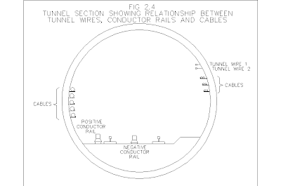
In tunnel sections of the system, a Tunnel Telephone system is provided to facilitate traction discharge and voice communication between the driver and Line Controller. Traction trip and speech is provided over two bare copper alloy wires carried, one above the other, on pairs of porcelain insulators supported on metal brackets fixed to the tunnel wall, usually on the right-hand side in the normal direction of travel. The insulators are generally provided every 6 metres along the tunnel so as to keep the wires about 115mm apart. The wires are positioned so as to be accessible by leaning from the driving cab window of a train. The general appearance of a single-bore deep tunnel is shown in Figure 2.4 below.

Where it is necessary for the tunnel wires to be carried across to the opposite tunnel wall, Over Track Crossings (OTX) are provided using cable. Where different sections of tunnel wire need to be interconnected, or equipment introduced, cabling is used and test boxes with sliding disconnection links may be provided to facilitate fault-finding.

Related posts on this website

All my posts on London Underground can be found here.

This topic is continued at London Underground - Traction Power Distribution (2).

[Bleed resistor values transposed, link to part (2) added 11-Apr-2021]

Tuesday, 10 February 2009

German Railway Signalling

This is a fairly superficial introduction to German railway signalling, intended to illustrate how different countries have evolved different solutions to the same basic problem of moving trains safely around the network.

Each European country has its own national variant traditional signalling system. Broadly, they may be divided into two types:-
- Route signalling, as in the U.K., where the specific route set is indicated to the driver
- Speed signalling, as in Germany and most European countries, where the maximum safe train speed is indicated to the driver, but the particular route set is not indicated.

In Germany, early colour light signals are according to system 'HV' using red, yellow, green and white lamps. More modern installations use system 'KS' where the signal lamps are supplemented by speed indicators for both Main and Distant signals.

The Hauptsignal (Main signal) is a stop signal. To allow sufficient braking distance for a train to stop at an adverse signal, each Main signal is preceded by a Vorsignal (Distant signal). This is a warning signal which may be passed when showing a restrictive aspect. The sequence of Distant signal, Main signal suffices where main signals are at least 1300m apart, otherwise a Distant signal is provided on the same post as the previous Main signal and, where this does not provide sufficient braking distance, also on the Main signal previous to that.

The heading photograph shows two Hauptsignal (main signal) at the north end of Mannheim Hauptbahnhof. Signal P004 on the left controls northbound departures from platform 4 and signal P003 on the right applies to platform 3. I believe the 'double red' is to prohibit passing the signal for shunting purposes, as well as prohibiting departure. The green lamp is above the red signal lamps. Below are two diagonal white lights which, when lit, authorise shunting movements beyond the red signal. Below the shunting signal is the yellow lamp forming part of the main signal allowing the 'green over yellow' aspect. When 'green over yellow' is displayed, the speed indicator at the top of the post (backed by a triangular sighting board) indicates the authorised reduced speed, in km/h divided by ten. Mounted lower down the post is the Distant signal indicating the aspect of the next Main signal.

This Distant signal is provided halfway along platform 3 at Mannheim, serving as the warning for signal P003, visible in the background. To indicate that the signal is less than the braking distance from the Main signal, a white light is displayed to the left of the signal. There will have been a previous warning signal at the full braking distance. The distant signal has two 2-lamp clusters, each showing Yellow or Green. The picture shows the 'double yellow' warning. When the main signal is displaying a proceed indication, the Distant displays a 'double green'. Where necessary, the 'green over yellow' indication can be given, indicating that the following Main signal is showing proceed at less than the line speed.

This picture shows two more Main signals at the north end of Mannheim Hauptbahnhof. Signal P002 on the left controls northbound departures from platform 2 and is showing 'double red'. Again, there are green and yellow lamps, plus a shunting signal and a numeric speed indicator at the top of the post. The cluster of three lights forming an 'A' is the 'Substitution signal'. These white lights, when lit, authorise a train to pass a defective Main signal which cannot be cleared. Lower down the post is the Distant signal for the next main signal, with a white light to indicate that it is less than the full braking distance from the Main signal.

Signal P001 on the right applies to platform 1. The grouping of lamps is a little more compact and the Shunting signal has additional lamps. The Main signal is displaying 'green over yellow' for proceed at reduced speed, as indicated (in this case) by the '5' in the speed indicator at the top of the signal for 50km/h. Mounted lower down the post is the Distant signal showing 'double yellow' indicating that the next Main signal is displaying 'stop'.

An elevated shunting signal is shown on the extreme right, applying to southbound moves on platform 4. Note the climbing brackets attached to the post to allow access to the signal head and the reflective red and white identification panel attached to the post to make the signal more visible to an approaching train. Another shunting signal applying to northbound moves on platform 4 can be seen, just behind the approaching 'ICE' train. A similar signal is mounted on the platform canopy of platform 3.

A snatched (rather fuzzy) picture of a Main signal as we passed at speed. Main signal at the top of the post. Below this, a shunting signal displaying two white lights diagonally and below this the yellow main aspect (to permit 'green over yellow' to be displayed. The separate cluster of three (yellow) lights forming a 'V' is the Caution signal. When illuminated, it allows a failed main signal to be passed. Below this, is the familiar diagonal pair of 2-lamp clusters of a Distant signal. Lower down the post is the signal number plate and the red and white reflective identification panel. There is no access ladder but the construction of the post presumably facilitates climbing. There are, however two landings with handrails to assist the maintainer - one by the main signal cluster, one by the distant signal. Finally, notice the two signalling equipment cases at the foot of the post.

.

Another Main signal, near Frankfurt. All the standard aspects are provided but, in addition to the Main signal speed indicator at the top of the post, there is a Distant speed indicator (displaying yellow numbers) beneath the Distant signal.

.

.

.

.

.

.

.

.

.

A main signal mounted on a bracket, presumably to improve sighting, on the approach to Frankfurt. This is a 'KS' system 'Combination' signal. The three Main lamps (red, yellow, green) are arranged in an 'A' to serve as a combined Main and Distant signal. It displays 'single red', 'single yellow', 'single green' or (when the Distant Speed indicator is lit) 'flashing green'. There is a Speed indicator above the Main signal and a Distant Speed indicator below the signal. The red and white identification panel indicates a Main signal - the yellow triangular identification panel is used in the 'KS' system to indicate a Distant signal.

.

.

.

.

.

A final example of a bracket signal, near Frankfurt Hauptbahnhof. This appears to be a 'KS' system Distant with yellow and green signal lamps and a Distant Speed indicator below.

.

.

.

.

.

.

.

.

.

.

As can be seen, conveying speed information to drivers can result in quite complex trackside equipment so the trend is now towards 'Cab Signalling' where speed information is presented in the cab and there may be no fixed signals along the route. But that's another story.

The pictures in this article are taken from my collection on German Railways.

Information on railway signalling in Germany is taken from 'European Railway Signalling', published by A & C Black for the Institution of Railway Signal Engineers (ISBN 0-7136-4167-3).

Saturday, 7 February 2009

High Speed Trains

Having been so beastly about our rail service in 'Brave New Railway', it's only fair that I comment again when I have a good journey. The only problem is that the good journey was on an 'Inter City Express' (ICE) service in Germany.

I'd flown to Frankfurt with two people from my client to attend a meeting in Mannheim. Terminal 1 at Frankfurt Airport is linked to stations serving both main and suburban rail lines. The ICE service offered the fastest connection to Mannheim and we'd time to buy a ticket for three at the multi-lingual ticket machine before descending to the platform. Clear displays on the platform showed train details and the layout of the train (including catering facilities). Announcements in English and German apologised for the 5 minute late arrival (most of which had been recovered by the time we got to Mannheim).

The Siemens-built ICE train was warm, the decor both inviting and relaxing and we readily found suitable seats. There's a pleasant air of spaciousness - the design benefits from the Berne Loading Gauge which is more generous than the British Loading Gauge. In addition, our 'Pendolinos' and 'Super Voyagers' are designed to tilt, resulting in a cabin narrower at the ceiling than the floor to ensure a tilted body remains within the loading gauge. The ticket inspector was friendly and chatted in English to us. Toilets were clean and everything worked. The ICE isn't cheap, but you have the option of travelling on a regional train at about half the price. We arrived in Mannheim suitably impressed.

The next day, when our meetings were finished, we travelled from Mannheim to Frankfurt itself. A pleasant, right-time experience. We were a little puzzled when the train first stopped at Frankfurt Airport and then, after a pause of a few minutes, reversed to travel on to Frankfurt Hauptbahnhof. Later that day, we returned to the airport, this time using the suburban 'S-Bahn' service - a far more basic service for which we paid far less. All-in-all, a satisfying experience.

It must be about 25 years since I was last in Frankfurt (visiting the German consultants employed on the Taiwan Trunk Line Electrification Project) and the railway scene is considerably changed. Then, 'DB' stood for Deutsche Bundesbahn which was a self-regulatory body. This has been turned into a public limited company, Deutsche Bahn AG, regulated by the Federal Railway Office Eisenbahnbundesamt (EBA).

The heading photo shows our ICE train on arrival at Frankfurt Hauptbahnhof. More pictures.

An Apology

My friend Chris pointed out a number of mis-spelled place names in my post 'Halfex to Blackpool'. I've corrected these errors (with a tinge of sadness - what I'd described as "wonderfully named Bashalls Sidings" becomes the prosaic Balshaws Sidings but see the Post Script below). If only those were the only errors!

As I say in '9:17 a.m. to Birmingham' "Would that I had been more diligent in recording the passing scene - my only defence is that I was young and just could not imagine that it would all be swept away". Many of the notes which I did make at the time are mislaid (it is some time ago!) but I decided to carry on and write down what I can remember and hope that more of the original notes eventually come to light. Not very likely until I give up work, I'm afraid. The more you try to remember details from that long ago, the less sure you become. For instance, I'm not certain now whether that train mentioned above was timed to leave at 9.17 or 9.18. I've mused about how difficult it is to get things right in 'Work in Progress'.

As far as recording the railway scene goes, I was usually just passing through on a train, frantically trying to make track and signalling diagrams as that was my principal interest at the time. Most of my exploits were on former L.M.S. lines, so the problem of identifying signal box names when passing at speed was easier than on many lines. The Great Western, for instance, produced a cast nameplate of often astonishing length which was fixed to the front of the box, facing the track. This could make it very difficult for a passenger to correctly identify the location. The L&NWR used individual cast letters, six inches tall, screwed to a board, again on the front of the box.

Initially, the L.M.S. used a similar arrangement but A. F. Bound, the Signal & Telegraph Engineer, had been impressed by the Great Central practice of fixing a nameboard at each end of the box - much easier to sight from a train. After some experimentation, the standard L.M.S. signal box nameboard appeared in 1935, using six inch cast letters fixed to a 9-inch high wooden board with a three-quarter inch rounded bead. For more details, refer to the excellent book 'A Pictorial Record of L.M.S.Signals' by L. G. Warburton, published by Oxford Publishing Company in 1972 (available, for a price, on the second-hand market).

L.M.S. pattern signal box nameboard photographed at Brereton Sidings in 2007

Railways could also be quite obstinate in the spelling they adopted. I've written about the signalbox at Sedgeley Junction. The nearby Sedgley Road West leading to the town of Sedgley both get by with only two 'e' in the name, but the railway invariably used three.

I shall continue to strive for accuracy and, no doubt, will continue to fail but I hope that something will be left to entertain or inform. To quote the Duke of Wellington (during an attempted blackmail attempt regarding letters he had written to a courtesan - I had to look it up, I knew the saying but not its origin): "Publish and be damned!"

Post Script

After I'd published this apology, my friend Chris confessed that, when he'd checked further, he'd discovered that the name 'Bashalls Sidings' was, in fact, correct.

Wednesday, 4 February 2009

Review of the Year, 2008

Last year I picked the word 'Antarctica' to describe the most significant experience of the year. This year, the word has to be 'Burma'. Yes, I know we're supposed to call the country 'The Union of Myanmar' but somehow 'Burma' seems to fit better. My first visit to Burma was the first stage of 'Round the world Five' in March 2008. That one trip gave me a lifetime's worth of experiences.

After visiting Rangoon (and a trip on the 'Circle Line' railway), I headed north for a river trip on the Irrawaddy. Rudyard Kipling wrote "Burma is like nowhere you have ever seen" and I found that's still true (My picture shows the massive golden pagoda of the Shwedagon in Yangon).

Leaving Burma with its friendly people and the 2,000 ancient temples of the Bagan Plain, my next stop was Las Vegas which provided something of a contrast, to say the least. I didn't take to the city but I loved the Grand Canyon and Hoover Dam and spent some time at the State Railway Museum at Boulder City.

Then, on to the Yucatan Peninsula in Mexico, where I looked at the Mayan city at Chichen Itza. The next country was Cuba. Havana and Trinidad were both quite special. I found a surprising number of deteriorating steam locomotives in two Havana 'museums' but the working steam trip on the Valle de los Ingenios line was cancelled because of locomotive failure. Instead, I did the trip on a diesel railcar (and got a short drive at the end!). Finally, I went to Panama. I enjoyed looking at the history, travelling on the newly-rebuilt Panama Canal Railway and, particularly, studying the operation of the Panama Canal. All the places on that trip were interesting, but it's my impressions of Burma that stay with me.

On my return, I booked to return to Burma in August 2008 for a different river trip but, as so often happens, Fate intervened. On 2nd May 2008, Cyclone Nargis hit Myanmar, causing terrible damage and loss of life. The ship I'd booked on was severely damaged and was taken out of service for repairs and a major refit.

Back in England, weekend footplate work at Peak Rail, the Battlefield Line and the Museum of Science and Industry in Manchester kept me busy. I've posted various write-ups, including a typical 'Driving Turn at Peak Rail'. I visited Tyseley Railway Museum at the end of June for the 'Tyseley 100' celebrations, meeting many old friends.

July was quite busy, with a visit to RSC Stratford to see 'Hamlet' with David Tennant, 'Day out with Thomas' events at the Battlefield Line and an Old Locomotive Committee (OLCO) meeting. Now 'Lion' has returned to Liverpool, OLCO activities are restricted, but I was observer, once again, at 'Lionsmeet 2008' which was held at Butterley.

I was involved in Peak Rail's 'Warring Forties' weekend in August (my picture shows me sporting a 'tin helmet') and attended my first 'Organathon' at Brewood Parish Church, then back to the Battlefield Line for a visit by 'Ivor the Engine'.

Although my August river trip had been cancelled, I went back to Burma at the beginning of September to meet my new friends and find out more from them about the ongoing relief work. My own journey continued to Mandalay and then to fascinating Inle Lake. Lots of temples to explore, culminating in a trip to Shan State and the 2,000 temples at mysterious Kakku. I returned to Yangon, said goodbye to my friends and flew to Chiang Rai in Thailand where I stopped at the Anantara Resort located at the 'Golden Triangle'. A day learning about elephants at the 'Elephant Camp' proved a moving (and occasionally wet) experience. Next, I made a rather undignified entrance into Laos on a small ferry in the pouring rain and joined a two-day cruise on the Mekong River. This proved totally absorbing and participating in the 'Big Brother Mouse Book Party' at a remote village school was quite emotional. Like most visitors, I was charmed by the old capital, Luang Prabang, before flying on to the more Western, but still distinctly Laotian, modern capital of Vientiane. Then, back home via Bangkok, pausing in Dubai. The city of Dubai didn't appeal, I'm afraid, but two nights at a resort out in the desert gave me a new experience.

In October, I was involved in three of the 'Day out with Thomas' events at the Battlefield Line in October (my picture shows 'Thomas' in one of his many 'incarnations'). We were very lucky with the weather for these 'Thomas' events. In December, I was rostered for a couple of days on the footplate with the 'Santa Specials' at Peak Rail and, again, the weather was fairly kind.

In the run-up to Christmas, over 80 members of Brewood Civic Society visited Brewood Hall and, a few days later, Warwickshire Baroque performed a Christmas Concert at the Hall (my picture shows the concert in progress and the 'Christmas Concert' report includes a video of part of the performance). Both events helped to raise funds for the relief work in Myanmar.

Well, these are some of the highlights of the year but there was lots more, too. When I'm at Brewood, my dog, Tai, and I are inseparable. In amongst everything else, I managed to work more-or-less full time during the year. In view of the fact that the world's financial systems appear to be in meltdown, I'd better plan to carry on working in 2009! It's a good thing I (mostly) enjoy work.

Finally, thanks and best wishes for the New Year to all my friends.