Wednesday, 24 June 2020

Power Signal Box, Togyaunggalay

Events on Sunday 5th May 2019, Yangon area 

In the post Return to Burma, I mentioned a visit to Togyaunggalay (Romanisation of Myanmar words can be a bit variable and there are various English spellings of the placename). My friend Doctor Hla Tun had arranged a visit to the elderly power signal box at Togyaunggalay station on the day I arrived in Myanmar. Earlier that day we'd visited the recently-commissioned Railway Operation Control Center in Yangon (described in a post here) after which the Doctor drove us through Yangon's heavy traffic to the junction station at Togyaunggalay.

The railway network around Yangon is shown below. Togyaunggalay station is situated on the double track main line from Yangon through Bago to Mandalay. A junction just north of the station connects the single line serving Dagon University. A junction south of the station leads to the single line to Thilawa.

Railways around Yangon (displayed on Togyaunggalay station)

In 2018, after visiting the railway at Bago, I'd travelled through Togyaunggalay by train (there's a description of that trip here) so I was pleased to have the opportunity to confirm the signalling arrangements. 

On our arrival in 2019, we reported to the Station Master and were conducted along the main platform to the concrete signal box and climbed the steps to the operating floor. The loud noise emanating from the ground floor equipment room indicated that the incoming overhead 3-phase electricity supply was absent and that the system was being run by the standby generator. The first floor equipment room was locked, so I couldn't study the relay interlocking equipment but continued to the second floor where we were welcomed by the signalman.

 Togyaunggalay signal box on 9th May 2018: Note radio antenna on left and incoming overhead 3-phase electricity supply terminated on frame on the right (Bago - Yangon by train).

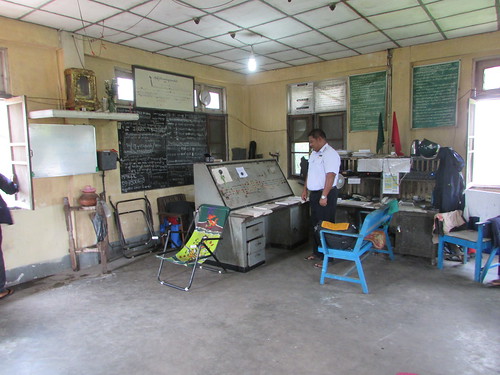
The railway signalling console was of the 'NX' pattern (there's a very brief explanation of this type of control in the section 'NX' pushbuttons of the post here) and used 'Mosaic' construction.The signalling console looked rather small, situated near one corner of the room. A desk just to the right was furnished with red and green flags, a number of telephones, two VHF radiotelephones for train control and a power amplifier and microphone for making announcements to waiting passengers. The windows overlooking the tracks behind the signalling console had been largely blocked by a large blackboard covered in what appeared to be useful telephone numbers. Above the blackboard was the usual framed drawing of the track layout and a clock. To the left, on a small shelf, was the customary Buddhist shrine.

Togyaunggalay: The operating floor of the signal
cabin, showing the Korean 'NX' signalling panel

A Mosaic Diagram, as the name implies, assembles a series of small 'tiles' into a frame. Each 'tile' has part of the signalling diagram on its face, together with the associated control switches and lamp indications. Each 'tile' can be individually removed for maintenance.

Mosaic Diagram Togyaunggalay - centre (Myanma Railways 2019)

I assumed that the siting of the blackboard was at least partly so that the lamp indications on the console were easier to see in bright sunlight, but nonetheless, I found some of them hard to interpret (or missing). They explained that spares, particularly the filament lamps used for indications, had become hard or impossible to source. They'd been forced to modify the circuits (in places using two lamps in series) but admitted that the result was not altogether satisfactory. Despite this, the signalman was carrying out his crucial tasks with the usual studied calm typical of signalmen everywhere.

Mosaic Diagram Togyaunggalay - detail (Myanma Railways 2019)

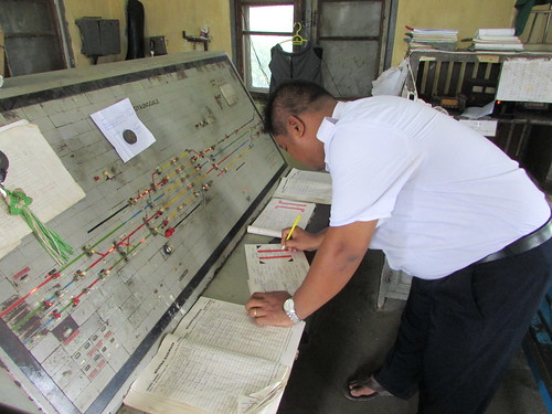
The flat desk area in front of the inclined control panel held two train register books and two books of paper Line Clear forms. 

Togyaunggalay Power Signal Box: Signalman completing Paper Line Clear Form

The Train Register Books serve a similar function to those used in the United Kingdom (described in a post here) although in Myanmar movements are separated into two books, one for 'Up' trains, one for 'Down'. Because of the importance of these logbooks, pages are individually numbered.

Train Register Book (Down Trains) Togyaunggalay

The British introduced railways into Burma (as Myanmar was then called) so signalling originally followed British practice, with reliance on telegraphy, telephony and special signalling equipment (like electric tablet systems for single lines). This relied on an open wire system using telegraph poles supporting cross-arms carrying porcelain insulators to which copper wires were attached. Remnants of this system can be seen throughout the country (invariably using an old length of rail as the 'pole') but, as far as I can determine, they have all fallen into disuse. Voice communication across the railway now uses VHF radiotelephones, allowing signalmen or stationmasters to authorise train movements from one 'block station' to the next. The permission is given to drivers in the form of a 'Paper Line Clear Form', shown in the picture below. Because of the vital nature of these forms, they are individually numbered, completed with some care and authorised with a rubber stamp.

Book of paper Line Clear forms: Togyaunggalay (MyanmaRailways 2019)

The pictures below show a local train from Yangon to Dagon University. In the first picture, the train has just arrived. The freight train seen waiting on the left was unusual in having a number of men travelling in open bogie wagons type SMBV, perched on piles of rock. The Doctor explained that the 'rock' was extremely valuable jade and the men were security.

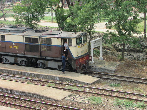
The second picture shows the signalman's assistant or 'runner' delivering the Paper Line Clear Form to the driver of the passenger train, authorising travel on the branch to Dagon University.

A freight waits for the signal (L) as a local Yangon-Dagon University arrives (R)

The signal box 'runner' delivers the paper Line Clear form to the driver

At the end of a fascinating tour, I made sure I checked out the throbbing standby generator on the ground floor - a substantial Daewoo packaged diesel alternator. Its claim to being 'sound proof' was a little undermined by the need to leave all the access doors open to prevent overheating (the outside air temperature was around 40 degrees Celsius that day).

Standby Generator Togyaunggalay (Myanma Railways 2019)

They explained that, even with the access doors open, the water-cooled diesel engine required periodic replenishment of water. Illustrating this point, as we left, a railwayman had just pushed a small platelayer's trolley along the platform line outside to the signal box, loaded with a plastic dustbin and a large plastic tub, both filled with water!

Cooling water for the Standby Generator at Togyaunggalay (MyanmaRailways 2019)

A most interesting day. I'd visited both the Railway Operation Control Center in Yangon and Togyaunggalay power signal box on the day I'd arrived in Myanmar and, later in the trip, I was to tour 'Mandalay Tower', the power signal box controlling Mandalay area.

My pictures

All my railway pictures around Yangon during my visit to Myanmar in 2019 are in the album below. Pictures may be viewed in various sizes or downloaded for non-commercial use.

Sunday, 21 June 2020

Infrastructure Problems (2)

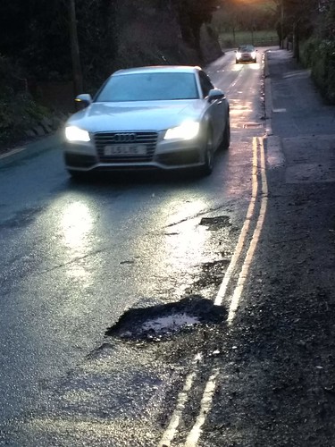
The road which passes the side of my garden, Sandy Lane, carries a formidable volume and variety of traffic so road 'patching' of potholes by the Council's contractor is frequent. I mentioned potholes in an earlier post called Infrastructure Problems, showing a typical example in Sandy Lane.

Pothole in Sandy Lane, Brewood in February 2019 

'Patching' is rather temporary. Over a few years, the area of road surface shown above has suffered  a number of separate potholes and the picture below (apologies for the poor quality) reveals at least five separate, overlapping attempts at making good in this small areas.

Overlapping pothole patching in Sandy Lane in November 2019

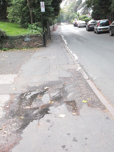
The long-term remedy is taking off the old tarmac and relaying, in a process called 're-surfacing'. Back in November 2012, a serious attempt was made at improving the junction between Sandy Lane and its continuation called The Pavement. I was quite impressed by the massive Cold Milling Machine used in this process, which I described in the post here. The surface on this section of road has lasted quite well but I soon noticed that they didn't manage to get the camber quite right to shed rain water. A recent picture (
which I took following failure of a water main) illustrates the effect.

Water in the left gutter from a burst main further up in Sandy Lane gets diverted by the camber to the right and then back to the left (Brewood Village)

To assist in shedding rain water, road surfaces are supposed to be cambered from side to side so as to direct surface water to the nearest gutter. At frequent intervals, this water should be directed underground into a surface water sewer pipe. Water enters the sewer via a series of gullies each provided with a hinged drain cover 
at road level, usually made of cast iron or cast steel.

This cover has a series of slots to admit water which passes into the sewer pipe via a U-trap, a larger version of the trap fitted under domestic sinks. The idea is to prevent solid material from being swept into the sewer but instead being retained in a chamber in the gulley, below the level of outflow to the sewer pipe. This should avoid blockages in the sewer pipe but over time sediment builds up, necessitating periodic removal before the gulley becomes blocked.

This is achieved by a sort of 'wet-n-dry' vacuum cleaner called a Gulley Emptying Vehicle. These vehicles usually also provide road-sweeping facilities, using contra-rotating brushes to remove debris and mud from the gutter and road surface.

A modern Gully-Emptying Vehicle parked in Sparrows End Lane in 2016 

Unfortunately, during the period of Government Austerity the United Kingdom has endured since 2008, gulley emptying seems to be low priority around here and many gullies have become blocked and ineffective.

In the post Infrastructure Problems, I outlined how mains water is normally a buried service. Until isolated or repaired, bursts or leaks on this network can result in the discharge of large volumes of water which either enter the surface water sewer via the gullies or generally saturate the surrounding earth. 

One example occurred, again in Sandy Lane, in 2013. A leaking buried water main announced itself by water flowing across the pavement and into the gutter. For some unknown reason (perhaps because it appeared to be a relatively minor leak) the water authority chose to defer repairs.

Sandy Lane. Water still leaking in October 2013.

It was October when the electricity suddenly failed. A quick look outside revealed that most (not all) of the village was in darkness so I didn't bother to check the house fuseboards. Power failure was not unknown at the time as the village has various overhead transmission lines which were prone to occasional failure, particularly during thunderstorms or bad weather. I can't remember how long it was before supply was restored but the electricity authority must have arranged some temporary 'workaround', because it was some days before permanent repairs were effected and the likely cause was revealed.

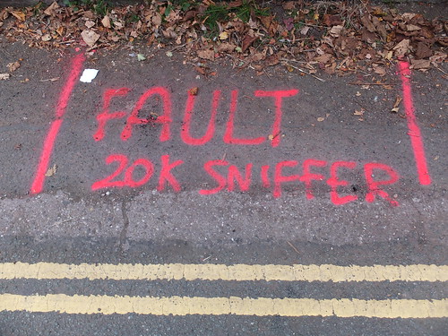
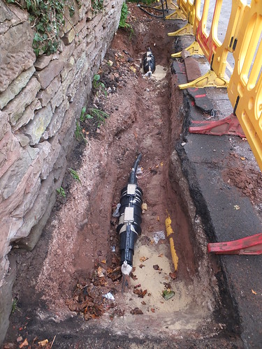
I found that they had located a cable fault underneath the road surface of Sandy Lane, a little downhill from the long-standing water leak and emblazoned the position with red spraypaint. A few days later the water leak was repaired and the electricity authority had dug a trench to locate the cable problem, which appeared to be the remains of a straight cable joint, blown apart and blackened. The conclusion seemed irresistible that the continuous saturation by water from the unrepaired leak has caused the elderly joint to fail. 

 The electricity fault has been located in October 2013. 

The repair to be cable was effected out the damaged cable joint and the cable on either side for a short distance and splicing in a length of new cable using two modern epoxy-filled joints.

The damaged section of electricity cable has been cut out
and a new section 'spliced in' between two modern epoxy-filled joints.

Just some of the pitfalls of living in a modern society! 

Pictures around Brewood Village 

The following album includes some examples of local services infrastructure:-
Brewood Village


Tuesday, 16 June 2020

Titfield Thunderbolt Film Posters

Some months ago when I was browsing on Abebooks (my first choice for books, particularly second-hand railway books) I came across BENITO ORIGINAL MOVIE POSTER based in Spain who were offering an original English poster for the 'Titfield Thunderbolt' film, showing the theft of the '14XX' by Dan and Mr. Valentine.


I'm afraid it would have set you back over £800 plus shipping but the Spanish poster for the film below was available at under £300.


You will note that, for Spanish-speaking audiences, the film had been re-titled 'LOS APUROS DE UN PEQUEÑO TREN' which, apparently, means 'The Troubles of a Small Train'.

I also found another poster for the film which used a mirror-image of the '14XX' artwork above but with the Spanish title.

Intrigued, I also found a poster on offer from CineMateriel for the French re-release. I discovered that 'Tortillard' is a term for a train, particularly a slow or roundabout local train, which I found rather charming.


Until I spotted the '14XX' poster above on the internet, I only remember having previously seen the Edward Bawden film poster, which I mentioned in my post The Titfield Thunderbolt and is repeated below, but a little more exploration showed that there are quite a few other film posters and artwork for DVD releases around. 

The Legend of the Titfield Thunderbolt lives on!

Wednesday, 27 May 2020

Brewood Village Road Re-surfacing

The road which passes the side of my garden, Sandy Lane, carries a formidable volume and variety of traffic so road 'patching' by the Council's contractor is frequent.

In November 2012, the junction between Sandy Lane and its continuation (The Pavement) was properly 're-surfaced', actually taking off the old tarmac and relaying. I was quite impressed by the massive Cold Milling Machine used in this process, which I described in the post here. The surface on this section of road has lasted quite well.

In May 2020, temporary road signs indicated that road works were to be carried out and on the afternoon of Monday, 18th May 19th May, there was activity in the afternoon as 'surface dressing' was carried out on Sandy Lane, from a starting-point beyond the junction re-surfaced in 2012 (which was left untouched) up to the village square. 'Surface dressing' is claimed to be a cost-effective way of restoring the road surface, sealing it and improving skid resistance. If you are interested, I found an interesting video by Dumfries and Galloway Council here which shows the whole process (including an ingenious method of confirming that the specified thickness of bitumen had been applied).

I viewed some of the proceedings from my garden and took a few pictures. There were a number of large vehicles, all painted canary yellow and carrying the logo 'RMS' in red, together with a number of workers, all wearing orange overalls with white 'hard hats'.


L-R: Chipping spreader, 8-wheel lorry with road chippings, road roller (Brewood Village: Road re-surfacing)

The contractors were Road Maintenance Services Limited, apparently in partnership with Staffordshire County Council and Amey. Road Maintenance Services Limited were set-up in 1947 by the Barlow family and remain family-owned. Their website is here and they claim to be 'innovators in surface treatments'. They are members of The Road Surface Treatments Association (RSTA), which was set up in 2008 and has its own website here.

A large, articulated tanker was marked as carrying 'Bitumen Emulsion'. This had a platform at the back for an operator to control machinery clearly provided to apply bitumen to the road being treated. A little internet research revealed that the manufacturers were a French company called Acmar, founded in 1946. Their English website is here and this type of vehicle is usually called a Bitumen Sprayer.


Articulated Bitumen Sprayer made by Acmar, showing adjustable spray bars and operator's platform (Brewood Village: Road re-surfacing)

There were two unfamiliar-looking four-wheeled rubber-tyred vehicles whose function seemed fairly clear. Chippings in a low-level hopper at the rear of the vehicle were transferred via an inclined conveyor to a second, smaller hopper behind the driving cab. The second hopper was then provided with a discharge mechanism to drop chippings onto the hot bitumen applied to the road surface by a Bitumen Sprayer. Following a bit more internet research later, I discovered the vehicles were called Chipping Spreaders. They were made by The Phoenix Engineering Co Ltd in Chard (website here). The machines appeared to be model MK7, now superceded by similar, later models but still available second hand. This company was originally formed in 1891 by a group of Londoners who acquired the Phoenix Iron Foundry which had traded since 1839. In 1891 Thomas John Jennings was company secretary and his descendants still manage the company.


Phoenix MK7 Chipping Spreader (Brewood Village: Road re-surfacing)

A little more research showed that what I call a 'road roller' was, more correctly, a 'VM75 Single Drum Soil Compactor' from the JCB 'Vibromax' range. Although the VM75 isn't manufactured now, there still seems to be a healthy second-hand market. One end of the machine is supported on the familiar wide drum but the other end is supported on two large, rubber-tyred wheels.


JCB VM75 Single Drum Soil Compactor (Brewood Village: Road re-surfacing)

By the time I observed the proceedings from my garden, they had already re-surfaced the downhill side of the road, so I watched as they treated the uphill side. First, the Bitumen Sprayer drove slowly uphill, laying down a ribbon of hot bitumen alongside the completed downhill strip.


Bitumen Sprayer at work (Brewood Village: Road re-surfacing)

One of the Chipping Spreaders lined up and one of the 8-wheel lorries was backed up to the rear of the Chipping spreader and coupled to it, allowing the low-level hopper on the Chipping Spreader to be continuously replenished from the lorry. The odd-looking combination then carefully followed the Bitumen Sprayer, laying down an even layer of small, grey chippings.


Chipping Spreader about to follow the Bitumen Sprayer (Brewood Village: Road re-surfacing)

The second Chipping Spreader appeared and waited as the second 8-wheel lorry of chippings was handsignalled to reverse up to the Chipping Spreader, after which these two vehicles slowly followed the first two.


Second lorry handsignalled towards the second Chipping Spreader (Brewood Village: Road re-surfacing)

Finally, the 'VM75' Road Roller slowly followed the other vehicles. I didn't stop to watch it performing but I'd found the whole operation very interesting.

My Pictures

Brewood Village: Road re-surfacing

Wednesday, 20 May 2020

Train Movements at Euston (2)

At the time of writing, the world is suffering from the serious, new respiratory disease Covid-19 and the U.K. is currently in 'Lockdown'. Only essential travel is permitted, resulting in train passenger numbers collapsing and revised timetables.

In the post Train Movements at Euston, I documented a few evening departures on 16th April 2020.

I've documented more incomplete fragments of arrivals and departures during the restricted Covid-19 timetable below.

I'm sorry the information is fragmentary. This is partly due to the internet becoming notoriously unreliable in these strange times, despite having a 'fibre to the cabinet' feed which on a good day produces at least 40 MBPS. With most people at home during 'Lockdown', at present internet speed is sometimes as poor as 0.2 MBPS with a 'ping' of 2 seconds, or it even becomes totally unresponsive.

Note 'VT' is the TOC code for Avanti, 'LM' is the TOC code for West Midland Trains.

Evening movements on 15th May 2020

Plat Nbr Dep Destination Nbr Arr From TOC
1 1F27 19:44 Liverpool 1M14 18:48 Crewe VT
2 1P06 19:18 Preston 1M13 17:58 Crewe VT
3 9G42 19:28 Wolverhampton 1B24 18:55 Wolverhampton VT
4 1B22 17:54 Wolverhampton
5 5D91
6 1H05 19:08 Manchester 1A52 18:19 Liverpool VT
7 1H07 Manchester 1A54 18:41 Manchester VT
9 2D46 19:15 Watford
.... Later ....
1 9G47 21:28 Wolverhampton 1M15 19:57 Crewe VT
3 9G45 20:44 Wolverhampton 1A59 19:49 Manchester VT

Lunchtime movements on 16th May 2020

Plat Nbr Dep Destination Nbr Arr From TOC
1 1H11 13:08 Manchester 1A02 10:54 Manchester VT
2 1H08 12:08 Manchester 1A05 11:43 Liverpool VT
3 1F15 12:51 Liverpool 1A06 11:59 Preston VT
4 1S63 12:12 Crewe 5S63 11:49 Wembley CS VT
5 9G50 12:31 Wolverhampton 1B04 11:28 Wolverhampton VT

Engineer's Trains on 16th May 2020

In the evening, three engineer's trains from Bescot arrived. The first was 6G50, a train of bogie ballast hoppers top-and-tailed by a pair of GB Railfreight Class 66. This continued to Euston before re-appearing on the Down Fast and slowly making its way to the work site which, as far as I could determine, was north of Primrose Hill Tunnels. Later, 7G52 arrived. This was hauled by another GB Railfreight Class 66. As it slowly passed the Railcam UK camera at Camden, also heading towards Euston, I could see it was an assortment of engineering materials with a number of bogie open wagons at the rear. I didn't follow matters but on Sunday morning these trains, together with Colas Yellow plant vehicle and 6G51 which appeared to be another ballast train were all showing up in describer berths apparently north of Primrose Hill Tunnels, surrounded by more berths displaying '****' in red, probably as a signalman's reminder of the work in progress.

Morning movements on 20th May 2020

At the time I wrote this, the Government were encouraging our railway system to increase services to help get the country back to work so just after 08:30 on Wednesday, 20th May 2020 I made another quick 'snapshot' of long-distance trains at Euston

Plat Nbr Dep Destination Nbr Arr From TOC
1 1R04 W'ton 05:45 VT
2 1H15 09:20 Manchester 1R12 11:43 W'ton 06:45 VT
3 1H63 09:40 Manchester 1R06 W'ton 06:04 VT
4 5H12 0741 Wembley CS VT
5 9P54 08:43 Preston 1R07 08:10 Lancaster VT
6 1F13 09:07 Liverpool 1R08 08:20 Manchester VT
7 1U27 08:46 Crewe 1U00 08:06 Crewe LM
8 1Y32 19:32 Birmingham LM
9 Local
10 Local
11 Local
12 5R11 09:12 Wembley CS 1R11 08:39/td> Liverpool VT
13 1Y08 08:13 Northampton LM
14 1S48 09:10 Glasgow 1R10 08:23 Manchester VT
15 0M16 Off sleeper?
16 1Y09 09:13 Birmingham 2B14 07:39 Bletchley lm


Wednesday, 13 May 2020

The Mersey Railway: Historical Notes

In the post Early Days of the Mersey Railway I outlined the construction of the tunnel and, in 1886, the opening of the line using steam traction.

Initially, there was only one station on the Liverpool side of the river, underground at James Street, accessed from street level by three large hydraulic lifts. From here, the railway line descended on a gradient of 1 in 27 under the river before climbing at a gradient of 1 in 30 to Birkenhead Hamilton Square station. Like James Street, this station was underground, accessed from street level by three large hydraulic lifts. The line continued south in a tunnel to the railway's headquarters at Birkenhead Central which was located in a cutting with retaining walls. The line extended south in cutting and tunnel to the final, sub-surface station at Green Lane.

At Shore Road, Birkenhead and Mann Island, Liverpool huge, steam-powered pumps were provided to keep the tunnel free of water.

At the time of the railway's opening, extensions to the line were already in hand. In 1888, the first to open was a branch in a tunnel from Birkenhead Hamilton Square to Birkenhead Park, to make an end-on connection with the relocated terminus of what became the Wirral Railway. This allowed through-running of Mersey Railway trains to and from locations on the Wirral, although locomotives were exchanged at Birkenhead Park. The extension from Green Park via cutting and tunnel to the surface station Rock Ferry and, on the Liverpool side, from James Street by tunnel (on a gradient varying between 1 in 31 and 1 in 34) to an underground station below the Liverpool Central station of the Cheshire Lines Committee were both opened in 1891.

Beyer Peacock supplied eight 0-6-4 and ten 2-6-2 condensing tank locomotives to operate the line.


Beyer Peacock 0-6-4 condensing tank for Mersey Railway (The Engineer)


Beyer Peacock 2-6-2 condensing tank for Mersey Railway (Railway Archive)

The condensing feature was used when travelling in tunnels. On arrival at Liverpool Central, a second locomotive was attached to the rear to form the departing train whilst the incoming engine uncoupled, 'dumped' the heated tank water, refilled with cold (conventional boiler feed injectors fail to operate reliably with hot water) and prepared to take out the next arrival.

Trains comprised eight 4-wheel passenger and one 4-wheel brake coach, each 27 feet in length.

With the extensions to the line in place, the railway offered good connections and a faster crossing than the ferries but using steam operation, conditions in the tunnels were foul, despite the massive fans provided, and revenue decreased, forcing the railway to continue operations in receivership.

Salvation came in 1903 in the form of an American, George Westinghouse, who was able to propose conversion to electric traction, using a fourth rail system operating at 650 volts d.c. Power was provided by three 1,650 h.p. generators driven by steam located in the pumping station at Shore Road, Birkenhead. Two, smaller 300 h.p. generators were also provided for lighting and other purposes.

Spacious bogie coaches to American design formed the replacement electric trains and these became popular with passengers, although no heating was provided. Air brakes were fitted but without compressors on the train, so periodically crews had to re-charge the train air receivers from an 'air main' at stations. All through-running at Birkenhead Park ceased.

At the railway 'Grouping', the Mersey Railway remained independent but the Wirral Railway became part of the L.M.S. empire. The Mersey Railway continued its role unchanged until 1938 when the L.M.S. electrified the Wirral lines (using the third-rail system). Running rights for the new L.M.S. electric multiple unit trains to operate to Liverpool Central and for the Mersey Railway electrics to serve the Wirral were established. The elderly Mersey Railway electrics required refurbishment to serve this extended role. Facilities to change between third-rail and fourth-rail current collection were provided, together with heaters and on-board electric compressors for the brake system.

Railway Nationalisation in 1948 finally brought an end to the Mersey Railway's independence and it became part of British Railways London Midland Region. But, repainted and renumbered, the Mersey Railway's electric trains carried on until 1956 when LMS-design electric multiple units started to replace the elderly vehicles. The last was withdrawn in 1957.

In 1977, the ambitious 'Liverpool Loop' scheme was opened by British Rail. This extended the line beyond Liverpool Central station so as to serve Liverpool Lime Street station by a reversing loop.

In recent years, I've looked at stations on the original Mersey Railway as part of a study of the modern Merseyrail system and there are notes below on three of those stations.

Birkenhead Central

The railway's headquarters at Birkenhead Central were fitted into a cramped location below ground level bounded by a cutting on one side and retaining walls abutting the gas works on the other. The station provided two through platforms, a south-facing bay, the 3-road steam locomotive shed and a carriage shed, as shown on the fragment of the 1912 Ordnance Survey map below. The right hand edge of the map shows the LNWR/GWR joint line which ran from Birkenhead (Woodside) to Chester (General). The large Engine Shed in the lower half is actually two engine sheds side-by-side for the LNWR and GWR.


Birkenhead Central station 1912: Birkenhead 25 inches to 1 mile map (National Library of Scotland)


The modern satellite view below shows what has survived. The platforms and station buildings are still there but the bay platform has become a siding. The carriage shed has been re-roofed and, in a different form, extended. The Mersey Railway steam locomotive shed has gone, as has the adjacent gas works (although some of my pictures from 2014 reveal abandoned steelwork which formed part of one of the access stairs to a rolling lift gasholder which I believe replaced the column-supported designs shown on the 1912 map). The large LNWR/GWR locomotive shed has gone and the area is overgrown.


Birkenhead Central station: satellite view (Google Maps)

Below, a few illustrations of Birkenhead Central over the years.


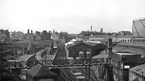
Birkenhead central in steam days, drawn by T. Raffles Davison (Mersey Railway)


Birkenhead Central, 1961 (Photo: Ben Brooksbank CC BY-SA2.0)


Merseyrail: Birkenhead Central in 2014, showing former carriage sidings.

Green Lane

The railway is below street level with a tunnel to the north leading towards Birkenhead Central and a short tunnel to the south, leading towards Rock Ferry. There are two platforms, set in a rectangular excavation with the retaining walls beautifully-executed stonework. A series of plate girders span the station and the spaces between these girders are partially infilled by brick arcading but only above the southbound track, giving the station a rather 'lopsided' appearance. I presume this was to support trackwork leading to the LNWR/GWR steam locomotive sheds serving the joint Line from Chester to Birkenhead Woodside which ran slightly to one side of Green Lane above ground level. Quite generous station buildings were provided at street level.


Birkenhead Green Lane station 1912: Birkenhead 25 inches to 1 mile map(National Library of Scotland)

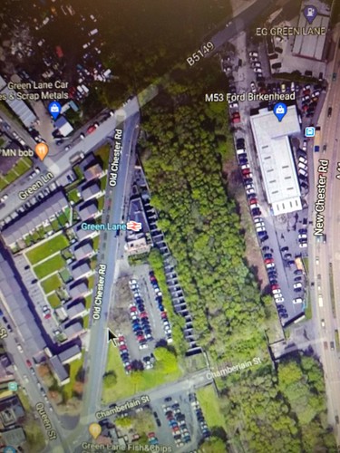
The modern satellite view below shows that the railway is little changed. The multiple plate girders bridging the station are clearly visible. The whole of the area where the joint line once ran is abandoned andvery overgrown with vegetation. The station buildings with their wedge-shaped plan remain.


Green Lane station: satellite view (Google Maps)

Below, pictures illustrating changes at Green Lane over the years.


Green Lane station in steam days, looking north, drawn by T. Raffles Davison (Mersey Railway)


Green Lane station, Merseyrail in 2020, looking south, showing stonework, overhead plate girders, partially infilled by brick arcading, and short tunnel towards Rock Ferry.

Rock Ferry

The 1891 southwards extension of the Mersey Railway to the surface station at Rock Ferry offered platform-to-platform interchange with the through platforms on the LNWR/GWR Joint Line which ran from Birkenhead (Woodside) to Chester (General). Mersey Railway trains ran to two terminal platforms provided with a middle engine release siding. North of Rock Ferry Station, at Union Street, connections were provided between the Mersey Railway and the Joint Line but I believe these were originally not much used.


Rockferry station 1912: Birkenhead 25 inches to 1 mile map (National Library of Scotland)

The modern satellite view below shows the major changes to the railway. The two terminal platforms of the Mersey Railway survive but the engine release road is now removed. The four tracks of the Joint Line have gone, but the Mersey Railway route has been slewed to occupy the trackbed of the Western pair of Joint Lines. The trackbed of the Eastern pair of joint lines was retained for a time to provide connections to the Birkenhead Docks railway system, but these are out of use. The island platform serving one terminal platform and the northbound through platform is re-roofed but not much changed. The southbound through platform is modernised and the associated access footbridge is new.


Rockferry station: satellite view (Google Maps)


Rock Ferry station in 2016 - terminal platforms 4 and 3, looking north. There was originally a 'middle siding'.


Rock Ferry station in 2016, view looking north from footbridge.

Thomas Raffles Davison

The pencil sketches of Birkenhead North and Green Lane above are the work of Thomas Raffles Davison (1853-1937), a prolific architectural illustrator, journalist, editor and occasional architect. There's a Wikipedia article about him here.

Books

[1] ‘The Line Beneath The Liners: A hundred years of Mersey Railway sights and sounds’ by John W. Gahan, published by Countyvise (ISBN 0 907768 40 7 and Avon AngliA Publications (0 905466 57 8).
[2] ‘Chester to Birkenhead including the Helsby Branch’ by Vic Mitchell and Keith Smith (Middleton Press 2012) ISBN 978 1 908174 21 5.

Posts on this website referring to Merseyrail

Early Days of the Mersey Railway 8-Oct-2013.
Day Trip to Liverpool 24-May-2010.
By rail to Liverpool (Part 2) 24-Mar-2014.
Birkenhead and New Brighton by train (Part 1) 19-Feb-2014.
Birkenhead and New Brighton by train (Part 3) 24-Feb-2014.
Railways around Birkenhead 28-Feb-2014.
More Merseyrail 21-Oct-2014.
Return to Liverpool 19-Mar-2020.

Quite a few of my posts relate to Merseyside. Your can display all these posts, in reverse date-of-posting order, by selecting Label 'Merseyside' or click here).

My pictures on the Merseyrail network

Where necessary, clicking on an image above will display an 'uncropped' view or, alternately, pictures may be selected, viewed or downloaded, in various sizes, from the albums below:-

Albums showing stations discussed in this post:-
Birkenhead Central Station
Green Lane
Rock Ferry

Merseyrail.
Profile - 'Cecil Raikes' (The locomotive).


Tuesday, 12 May 2020

Glenbrook Vintage Railway

At the end of 2001, I made my first Round the World Trip, cryptically referred to as 'RTW1'. I hadn't started 'blogging' then, so I'd written very little about the trip. The pictures I'd taken were 35mm and scanning has proceeded very slowly. But (only 18 years later) I decided to add the following description of my afternoon at a preserved railway.

During my time in Auckland on that trip, I travelled by car to Glenbrook Station on the Glenbrook Vintage Railway. In the run-up to the New Year, they were operating their large 'Ja' class locomotive. New Zealand built in 1949, this 3 foot 6 inch gauge 4-8-2 has many American features, including a Vanderbilt tender.


Ja1250 preserved at Glenbrook Vintage Railway (Photo: G.V.R.).

A board, displayed at Glenbrook Station, gave a brief specification of Ja1250.


Brief specification of Ja1250 (Glenbrook Vintage Railway, 2001)

I purchased a ticket at the booking office and enquired about the possibility of a footplate ride. "Ask the driver" I was told. When I explained to the driver and fireman my involvement in steam preservation in England, I was immediately welcomed aboard. There was also a young trainee firing. I offered to "work my passage" by firing and thought, for a moment, I'd offended some protocol by the vehemence of the driver's refusal. But then he explained "It's all downhill this way - you can have the shovel on the way back!".

The driver (the locomotive is right-hand drive) kept a look-out for the guard's 'right away', given by whistle and green flag, just like the U.K. I noticed the Australian-made Westinghouse brake stand incorporating driver's brake valve for both the air brakes on the train and 'straight air' brake on the locomotive.


Waiting for the guard's 'right away' (Glenbrook Vintage Railway, 2001)

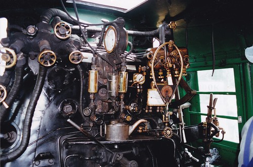
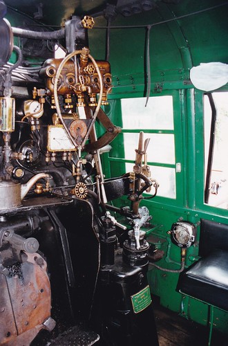
The boiler backhead had a number of interesting features. The Steam Fountain was placed on the fireman's side of the cab, so both injector steam cocks were that side - a convenient feature that I don't think appeared in British practice until Bulleid. The most of the exposed steam pipes were lagged. The boiler pressure gauge was dual-faced, electrically-fit and mounted on a bracket perpendicular to the backhead to improve viewing by both driver and fireman. Below the pressure gauge were dual gauge glasses and an electric gauge lamp. A large oil feeder sat on the warming tray above the 'Ajax' firedoors, with their manual operating handle. These are often called 'butterfly' firedoors because of the pivoting action of the doors. At high level in front of the driver a large 'Detroit' 5-feed hydrostatic (sight-feed) lubricator was fitted. A large hoop hooked onto the filler plug of the lubricator carried the single line tablet for the line we were about to travel from Glenbrook to Pukeoware. To the right of the lubricator, a pull-out regulator hung from the roof. A trigger lever worked a catch in a toothed quadrant to hold the regulator in the position set. Immediately in front of the driver was the brake gauge, also fitted with an electric lamp. To the right, the reversing lever which American's call the 'Johnson Bar', was miniature and fitted with a trigger lever working a catch in a toothed quadrant implying power operation.


Ja1250 boiler backhead (Glenbrook Vintage Railway, 2001)

Electricity is provided by a generator which feeds the large headlamps provided front and rear and the various other lamps. I spotted a Train Recorder mounted on the the inside of the cab side sheet on the driver's side. I didn't have time to absorb all the other details in the cab (including what appeared to be another lubricator with 4-feeds) before we set off, with the engine working tender-first. Easy steam was sufficient to give a reasonable speed downhill and the trainee fireman was firing lightly. 'Ajax' firedoors are intended for power operation and I was impressed that this feature was working on Ja1250, foot pressure on a small floor-mounted treadle swinging the doors open as the loaded shovel blade approached the firehole. A small air cylinder on the backhead above the firehole provided the power to operate the firedoors.

In the U.K., Bullied fitted 'Ajax' firedoors to his 'Pacifics', powered by a small steam cylinder. I've worked on two preserved Bulleid 'Pacifics' ('Canadian Pacific' and 'Taw Valley') but the power operated firedoors weren't in use on either and a former British Rail fireman told me that was not uncommon during his time on the Southern Region.


Ja1250 cab view with 'Ajax' firedoors bottom left (Glenbrook Vintage Railway, 2001)

The line led through attractive, wooded farmland, not unlike England. Whistling, we passed over a minor road crossing, no barriers, just warning signs on the road.


Approaching Morley Road level crossing (Glenbrook Vintage Railway, 2001)

All too soon, we arrived at what was then the end of the line. I climbed down to watch the locomotive being uncoupled - flexible hoses on the air brakes isolated and the palm couplings separated, then the Norwegian-pattern 'chopper' coupling disconnected.


Ja1250 being uncoupled from its train (Glenbrook Vintage Railway, 2001)

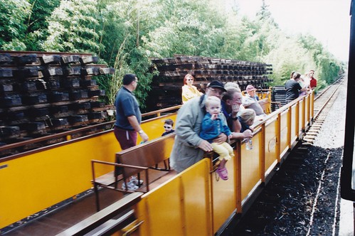
The locomotive was then set-back into the headshunt, points reversed, and run forwards along the run-round loop, closely watched by the passengers, particularly those in the end vehicle - an open, converted bogie freight wagon.


Ja1250 setting back into headshunt (Glenbrook Vintage Railway, 2001)


The train included an open, converted bogie freight wagon (Glenbrook Vintage Railway, 2001)

During the run-round, the locomotive stopped to take coal from an adjacent coal heap, using a small jib crane fitted with a grab. The crane was air operated by connecting a long hose to the brake hose on the locomotive and using the compressor on the locomotive to power the crane. I'd come across locomotive turntables using an air motor powered from the engine being turned (in the U.K., because of the original predominance of vacuum brakes, vacuum tractors were the norm) but I'd not encountered other equipment powered in this way. The 'Ja' then completed the run-round and was coupled-up for the return journey.

I'd been invited to see if I could make the 'Ja' steam on the way back to Glenbrook, where the gradient was reported as 1 in 50. The fire looked in good shape, but I decided to thicken it a little in the hope of bringing the pressure near to 'blowing-off' by the time we set off. There was plenty of 'Strongman' hard coal in the tender, in a convenient size for shovelling, so the challenge was to synchronise operation of the foot treadle so that the firedoors opened before the shovel blade tried to enter the firehole and keep pressure on the treadle until the shovel blade was completely withdrawn. Quite quickly, I managed to get a reasonable rhythm and found the experience delightful, musing that it was a distinct improvement on the usual arrangements in my country! I was gratified to see the boiler pressure respond to my treatment and, on the ascent back to Glenbrook, my usual 'little and often' treatment produced satisfactory results. The trainee decided to deal with the live steam injector, so I didn't get a chance to master setting the unfamiliar pattern in use. We arrived back at Glenbrook and I let the trainee have the fire back, thankful that I'd not disgraced myself.

The 'Ja' class had a good supply of 'Strongman' coal in the tender (Glenbrook Vintage Railway, 2001)

I stayed on the footplate as the crew ran Ja1250 round its train, ready to take the next service, then I thanked them for their kindness and reluctantly returned to the platform.


The crew on Ja1250 during my visit (Glenbrook Vintage Railway, 2001)


Ja1250 leaving Glenbrook (Glenbrook Vintage Railway, 2001)

Ja1250 leaving Glenbrook. Note the design of the Guard's ducket window (Glenbrook Vintage Railway, 2001)

Whilst the service train was down the line, two motorised inspection trollies were raising funds for the railway by offering rides the length of the station. I was tempted, but declined.


Motorised Inspection Trolley (Glenbrook Vintage Railway, 2001)

Only much later did I discover that, in 1967, the original Strongman deep mine, near Greymouth on New Zealand's South Island, had suffered a disaster which killed 19 miners. It was replaced by the Strongman 2 mine which operated from 1994 to 2003.

My pictures

Glenbrook Vintage Railway