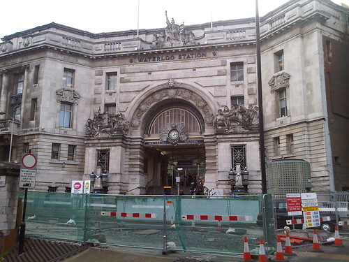
 A modern view of the former L.S.W.R. London terminus at Waterloo showing the imposing main entrance for foot passengers, rather spoilt by the temporary works in the foreground. After the 'Great War' of 1914-1918, this entrance became the Memorial to L.S.W.R. staff lost in World War I.
I was brought up in the Midlands in the early days of the post-war Nationalised railway so, although I was familiar with both the former L.M.S. and G.W.R. lines, the former Southern Railway was very much a 'foreign railway' to me. It was some time before I started to discover some of the history of the lines in the south of the country.
Upon Nationalisation in 1948, the Southern Region of British Railways absorbed the assets of the Southern Railway. The Southern Railway had been created in 1923 by the government-directed grouping of railways into the 'Big Four' (L.M.S., G.W.R., L.N.E.R. and S.R.). The Southern Railway brought together the London Brighton and South Coast Railway, the South Eastern and Chatham Railway and the London and South Western Railway.
Brief early history of the London and South Western Railway
I've mentioned some early railways in England in the post here and this mentions the origins of the London and South Western Railway. The success of the Liverpool and Manchester Line which opened in 1830 encouraged the promotion of the London and Southampton Railway as early as 1831. A limited service started on 21st May 1838 between a London terminus at Nine Elms and Woking Common. As construction of the line towards Southampton continued, the name of the railway was changed to the more impressive-sounding 'London and South Western Railway'. I believe this was to avoid offence to the people of Portsmouth (who considered Southampton a modern upstart) as the railway planned an extension to Portsmouth. The railway used this new name (or the contraction 'South Western Railway' or simply the 'South Western') without change or amalgamation until the Grouping in 1923.
The initial route to Southampton was opened throughout in 1840. A branch to Richmond was opened in 1846 but the growing traffic showed up the inadequacy of Nine Elms as a terminus. An extension was authorised from Nine Elms to a new station near the south end of Waterloo Bridge.
Both the new line, (which, ambitiously, had four lines from the start) and the new station, called 'Waterloo', were raised on arches. On the 4-track extension over the arches, the western pair of lines were used for Richmond Line Trains. The Richmond line was extended to Windsor in 1849 and the term 'Windsor Lines' was coined for the western pair of lines. Today, there are eight running lines into Waterloo but the western group are still the 'Windsor Lines'.
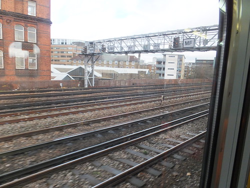 View from Up train approaching Waterloo. L-R: Windsor Reversible, Up Windsor, Windsor Fast, Windsor Slow, Main Fast.

A modern view of Waterloo Station (centre) with Hungerford Bridge leading to Charing Cross station towards the top. Although the station and rail approaches are much extended, the way in which the line from Nine Elms was extended over arches is still apparent. On the north bank of the Thames note the Palace of Westminster (left), Whitehall and Trafalgar Square with Nelson's Column (right).
In 1848, Nine Elms was closed to the public (although retained for Royal Trains and goods) when all passenger traffic was diverted to Waterloo. The initial Waterloo Station had four platforms with two 'middle lines'. The L.S.W.R. intended to extend the line beyond Waterloo to get nearer to the City of London, which was the ultimate destination for many of its regular passengers. As a stop-gap, one of the 'middle lines' was extended to form a through connection with the South Eastern Railway (later to become the S.E.C.R.) but today there's only a pedestrian connection between the terminal platforms at Waterloo and the through platforms at Waterloo East. As an alternative, the L.S.W.R. supported the initiative to build an underground electric railway from Waterloo to the City. From the line's opening in 1898, the L.S.W.R. operated the railway on behalf of the Waterloo and City company, but it later acquired ownership outright. There's a little more on the Waterloo & City Line in the article here.
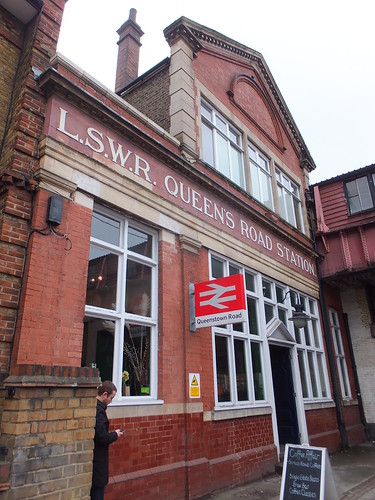
Queenstown Road station, opened 1877 on the extension to Waterloo, still proudly displays its L.S.W.R. origins and its original name, Queen's Road Station.
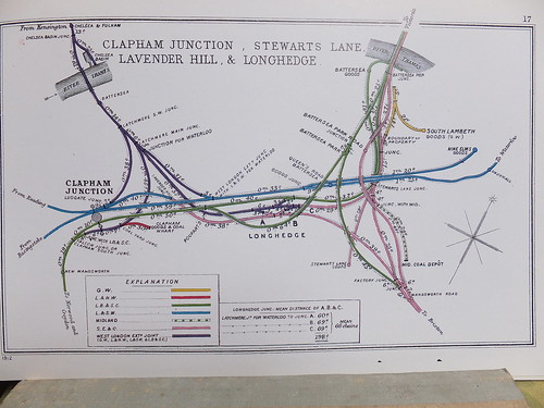 Click for larger image.
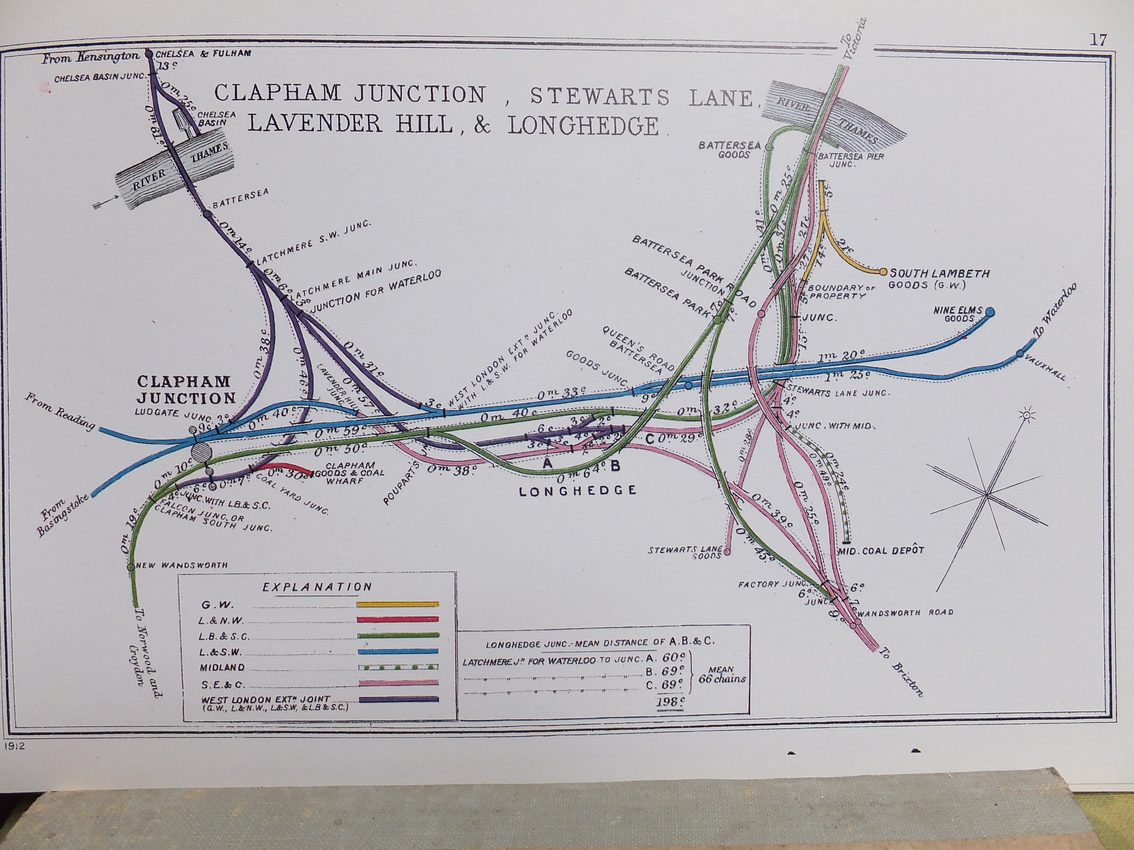
Details of the junctions between the L.S.W.R. and other railways in the vicinity of Clapham Junction. This diagram is one of a series prepared by the Railway Clearing House in 1914 which appear in the reprint 'Pre-Grouping Railway Junction Diagrams 1914', published by Ian Allen (ISBN 0 7110 1256 3).
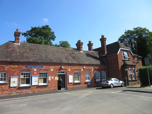 The attractive station building provided at London Road (Guildford).
Ultimately, the reach of the L.S.W.R. extended to the far west, covering Exeter, Plymouth, Padstow, Bude and Ilfracombe.
The section 'Related articles in this blog' (below) lists other posts concerning the L.S.W.R. around London.
Books
[1] 'The London & South Western Railway' O.S. Nock, published by Ian Allen.
[2] 'Locomotives of the London and South Western Railway Part 1' by D.L. Bradley, published 1965 by RCTS.
[3] 'The South Western Railway' by Hamilton Ellis, published 1956 by George Allen and Unwin.
[4] 'History of the Southern Railway' by C. F. Dendy Marshall, revised by R. W. Kidner reprinted 1982 by Ian Allen (ISBN 0 7110 0059 X).
[5] 'Great Locomotives of the Southern Railway' by O. S. Nock, Guild Publishing, 1987 edition by Book Club Associates.
[6] 'Southern Steam' by O. S. Nock, published by David & Charles (ISBN 0 7153 5235 0).
[7] 'London's Termini' by Alan A. Jackson, published by David & Charles (0 330 02746 6). (The L.S.W.R. Terminus at Waterloo is described in Chapter 11).
[8] 'Southampton's Railways' by Bert Moody, Waterfront Publications (ISBN 0 946184 63 1).
Maps
Details of what remains of the L.S.W.R. today are shown in two sections of the 'Quail Track Diagrams':-
'Railway Track Diagrams Book 5: Southern and TfL' Third Edition, published by TRACKmaps (ISBN 978-0-9549866-4-3).
'Railway Track Diagrams Book 3: Western' Fourth Edition, published by TRACKmaps (ISBN 0-9549866-1-X).
External Links
London and South Western Railway (Wikipedia).
Related articles in this blog
Waterloo Station, London.
Waterloo Station, London (Part 2).
London Underground: The Waterloo & City Line.
Clapham Junction Station, London.
By Rail to Guildford.
My Pictures
These are albums which include pictures taken in recent times showing former L.S.W.R. infrastructure:-
Clapham Junction.
London: former 'Southern' lines.
London's Railways.
Waterloo Station.
Tuesday, 17 November 2015
Origins of the Southern Railway: Part 1 - L.S.W.R.

Monday, 16 November 2015
Wolverhampton High Level Remembered
I prefer to recall the station as it was when I was growing up in the 'fifties although wartime had brought the whole of our railway system, including High Level station, to a low ebb. Sadly, I have no photographs of my own to supplement those memories but the books referenced in the earlier post mentioned above document that time. Below are a few specific memories.

Wolverhampton High Level Station as
I remember it, viewed from Railway Drive.
Overall Roof
At Wolverhampton High Level, platforms 1 and 2 were beneath an imposing overall roof of typical LNWR design. Electrification saw this demolished, of course. At least places like Crewe, Preston and others retain examples of the LNWR structures, even if modernised. The picture below shows a small, less-modernised section of this type of roof over platform 1 at Crewe.
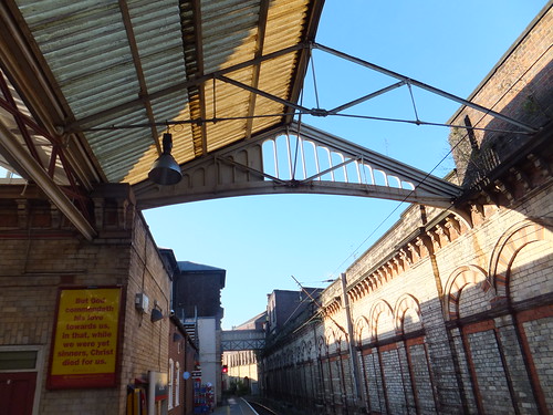 LNWR-style roofing at Crewe.
Footbridge
Near the Birmingham end of the Overall Roof at Wolverhampton there was another typically LNWR feature - the footbridge between platform 1 and the island platform serving platforms 2 and 3. This was also lost during the overhead electrification project but similar footbridges survive - the photograph below was taken at Narborough on the Nuneaton Leicester line. I remember the risers on the footbridge steps at Wolverhampton carried advertising - a repeated message on vitreous enamelled steel sheets but I can't remember the product promoted.
 At Narborough, the footbridge serves not only the two platforms but also the adjacent level crossing.
Access Tower
Platform 2 at Wolverhampton was home to a large, wooden access tower, looking like some medieval siege tower. I saw it in use by electricians replacing failed electric lamps but I presume it was used for any type of maintenance on the roof. It was on small wheels allowing it to be pushed into position and then a windlass and system of ropes allowed the telescoping sections to be raised and lowered.
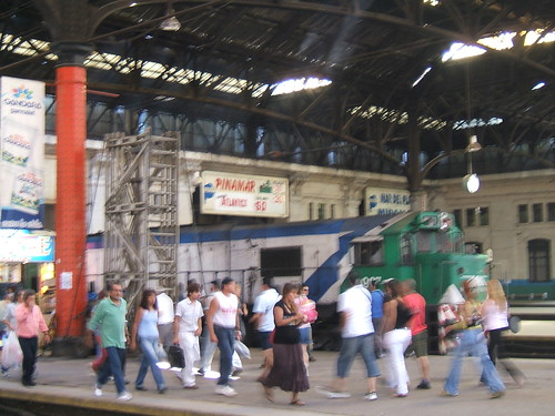
Platform adornments
At one time, I remember a large, detailed ship model in a glass case on the platform. I think it represented one of the Isle of Man ferries. At another time, there was a model of 'Rocket' in a glass case. By inserting a coin, an electric motor would rotate the driving wheels and operate the pistons and connecting rods. The proceeds were for charitable purposes (a railway orphanage, I think). There was usually a weighing machine to check your weight after inserting an old penny. More interesting was the label making machine. Here, again for money, you could produce your own labels by embossing a series of letters on aluminium strip. The inclined front face of the machine carried a single pointer which you turned to select the next character before pressing an embossing lever. This could prove disappointing as the aluminium strip had a habit of not indexing forward the right amount, resulting in overlapping characters. Even worse, sometimes the aluminium strip had run out.
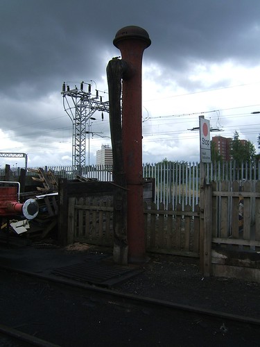
Water Column
The LNWR had a very austere standard design of water column. I often watched crews watering at the columns provided at the end of Platform 1 (Down) and Platform 2 (Up). There was no nonsense about a hinging crane arm that could be swung out to assist in insertion of the 'bag' - the rivetted leather hose which delivered water - into the filler on the engine. The fireman grasped a chain attached near the open end of the 'bag' and hauled it up to the locomotive filler. In frosty weather, this was particularly challenging. Freezing of the water main or water valve in winter was hopefully prevented by a small coal brazier to which firemen would add a few lumps periodically. The water valve was near the top of the column, operated by a lever near the base which moved from 'six o'clock' (closed) to 'twelve o'clock' (fully open). Very often, quite a torrent of water would spray from the top of the column, causing the driver (who usually operated the water valve whilst his fireman struggled on the top of the engine) to be cautious when trying to shut the valve. The movement was often completed by a judicious kick to the lever to ensure the valve had closed.
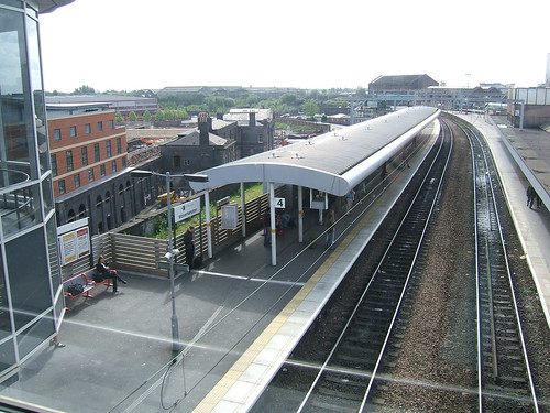
Wolverhampton Station Today
The modern station in Wolverhampton is a typically soulless affair as most of the features of its earlier history have been swept away. In the picture below, the 'new' platform 4 is on the left, sited on what, in steam days, were sidings and Up and Down goods lines.
For track diagrams of the modern railway around Wolverhampton, refer to 'Railway Track Diagrams' Book 4: Midlands & North West', Second Edition 2005, published by Trackmaps (ISBN: 0-9549866-0-1). The First Edition of this book was published by Quail in 1988.
My pictures
This album (started in 2007) gives an idea of the modern scene on West Midland's railways:-
West Midland Railways.
Wednesday, 11 November 2015
Wolverhampton High Level Station in Steam Days
 The restored Queen's Building, built 1849, formed the original gateway to Wolverhampton High Level railway station. It was designed by Edward Banks.
The southern approach to High Level from Portobello Junction on the Grand Junction Line involved a twisting, tightly-curved route.
In the diesel era, I had offices overlooking this approach and I remember one day when a driver attempted to re-start a long train of loaded 'HAA' hopper wagons destined for Ironbridge Power Station from a signal check on the tight curve. I'm afraid that, rather than follow the curve, the train 'straightened itself out' and most of the wagons tipped over on their sides.The Stour Valley line through Dudley Port diverged from the Portobello route at Crane Street Junction, curving in the opposite direction to exit Wolverhampton on a viaduct.
The through station was built on the straight, although the southern end of the platforms had to curve to reach Crane Street Junction. There were three platforms - Down (Platform 1), Up Main (Platform 2) and Up Loop (Platform 3). Platform 1 had a short bay platform at the Crane Street end, usually referred to as Platform 1 Bay. There was a 'Middle Siding' in between the roads serving platforms 1 and 2 accesible from either end generally used for 'parking' spare vehicles or locomotives. Platform 1 also had a short bay at the north end which stabled vans for sundries traffic.
The approach to Wolverhampton High Level from the north was difficult too - curved and also with a sharp gradient rising into the station. There was a group of carriage sidings on the Up side just north of the station, with a carriage shed a little further north. These sidings provided stock for originating London trains.
Near the end of the steam era, London trains were often hauled by 'Princess Coronation' class locomotives. One frosty, winter morning I remember the driver of a grubby 'Pacific' struggling for about fifteen minutes to move his rake of coaches from the carriage sidings into platform 3, watched by his cold, waiting passengers.

Click on the image above for a larger view
1903 Railway Clearing House diagram of the lines around Wolverhampton.
The station area was controlled by four manual signalboxes, all of London & North Western Railway (L&NWR) style and numbered 1 to 4 from the south, as was L&NWR practice. For signalling diagrams, refer to book reference [5] (below).
I only ever visited Number 1 box, which controlled Crane Street Junction. This box seemed to be called 'Crane Street' by railwaymen as often as 'Wolverhampton Number 1'. Standard L&NWR block instruments communicated with the adjacent boxes at Heath Town Junction on the original line from Portobello Junction, Monmore Green on the Stour Valley Line and, just 227 yards away, Wolverhampton Number 2. Running signals were upper quadrant, using various types of signal post. It was a cramped location and, at either end of the box, additional glazed lights were fitted in the gable end above the standard windows. This was a feature provided to assist signalmen in observing signals at locations where signals close to the box would be otherwise difficult to see. Unusually for this type of signal box, the lever frame was along the rear wall of the box, away from the track. Perhaps this was to improve the signalman's view of the curving layout of tracks?
When 25 kV a.c. electrification was decided upon for Britain's railways, it was High Level Station that was retained and the former Great Western Low Level Station that was abandoned. Whilst the refurbished Low Level Station Building remains as 'Grand Station Conference and Event Venue', very little of the High Level station from the steam era remains.
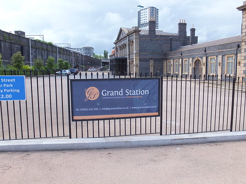 Left: Original retaining wall supporting the remaining station, Right: Low Level Station Building is now 'Grand Station'.
Books
[1] ‘Rail Centres: Wolverhampton’ by Paul Collins (originally published in 1990 by Ian Allen, reprinted by Booklaw Publications in 2008) ISBN 1-901945-23-5.Related posts on this site
[2] ‘Wolverhampton Railway Album Volume 1’ by Simon Dewey & Ned Williams (Uralia Press) ISBN 0 9500533 2 5.
[3] ‘Wolverhampton Railway Album Volume 2’ by Simon Dewey & Ned Williams (Uralia Press) ISBN 0 9500533 3 3.
[4] ‘Wolverhampton to Stafford’ by Vic Mitchell (Middleton press) ISBN: 978 1 908174 79 6.
[5] ‘British Railways Layout Plans of the 1950’s - Volume 11: LNW Lines in the West Midlands’ (Signalling Record Society) ISBN: 1 873228 13 9.
West Midland Railways.
9:17 a.m. to Birmingham.
More on Wolverhampton High Level.
My pictures
West Midland Railways.
Tuesday, 10 November 2015
'Single-Wheeler' locomotives
This is not a comprehensive review of British locomotive designs with just one driven axle but rather a gentle ramble around some of the candidates.
In a steam engine, steam is used to push a piston (connected to a piston rod) up and down a cylinder. The reciprocating motion of the piston rod is used to rotate an axle via a connecting rod. The axle, in turn, drives a load. Many early stationary engines worked like this without refinements.
But when it comes to locomotives, you really need two cylinders set to provide power at different 'angles' to get over the problems of starting. Early locomotives had two 'driving wheels' connected to the driven axle producing what's often called a 'Single Wheeler' (they would be more accurately described as 'Single Driving Axle' but I suppose since you can only usually see one wheel at a time, 'Single Wheeler' stuck). It's necessary to provide at least one more axle provided with non-powered 'carrying wheels' to make a practical locomotive - a rectangular vehicle with a wheel near each corner.
The 'Rocket' class
The first main-line passenger railway in the world was the Liverpool and Manchester Railway. The events leading up to the building of that line, including the Rainhill Trials (the competition held in 1829 to determine whether locomotive engines could provide the motive power, rather than using stationary engines and cable haulage), are briefly described in the post Early Locomotive Design.
The Stephensons (father George and son Robert) applied all the knowledge acquired building earlier locomotives for colliery haulage in producing 'Rocket', their entry for the Rainhill Trials. Their design placed the driving axle at the front and the carrying axle beneath the footplate which, in Whyte Notation we now call an '0-2-2'. The simplicity of this layout, combined with other sound ideas, particularly the multi-tubular boiler, gave the Stephensons victory in the Trials and the order to provide the motive power for the the Liverpool and Manchester Railway.
In 1830, Stephenson's built seven more of the 'Rocket' class locomotives ('Meteor', 'Comet', 'Arrow', 'Dart', 'Phoenix', 'North Star' and 'Northumbrian') for the Liverpool and Manchester Railway. Various alterations were made - larger cylinders, larger boiler diameter. The water-jacketed firebox was made larger and better integrated with the boiler barrel than in 'Rocket'. Some of these had a recognisable smokebox ('Rocket' had only a large 'elbow' to collect the hot gases from the fire tubes and divert them up the chimney). The inclined cylinders of 'Rocket' were changed for virtually horizontal cylinders, partly to reduce the "hammerblow" effect on the notoriously weak rails of the time.
The historical importance of 'Rocket' means that a number of working and non-working replicas have been built over the years, including the 1979 working replica, now held by the National Railway Museum.The 'Planet' class
The 1979 working replica of 'Rocket' in Manchester to celebrate the 180th birthday of the Liverpool & Manchester Railway.
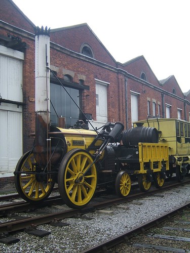
The pace of development was remarkable. The innovative 'Planet' design - almost as revolutionary as 'Rocket' had been - was also introduced in 1830. The cylinders were changed from 'outside' to 'inside' and placed in the base of the smokebox to reduce condensation losses, producing a '2-2-0' wheel arrangement. The disadvantage of this change was the need to provide a double-crank driving axle for the connecting rods to turn. With the production techniques of the day, broken crank axles were a risk so 'Planet' had both outside frames and inside frames to provide better support to the crank axle. Before the end of 1830, three more 'Planet' class locomotives had been built - 'Majestic', 'Mercury' and 'Mars'.
In 1831, more 'Planet' class were delivered to the Liverpool and Manchester Railway - 'Jupiter', 'Saturn', 'Sun', 'Venus', 'Vulcan', 'Etna', 'Fury' and 'Victory'. 'Vulcan' and 'Fury' were actually built by Fenton, Murray and Company to the Stephensons' design.
The significance of the 'Planet' design led the then Museum of Science and Industry in Manchester (now Museum of Science and Industry and part of the Science Museum Group) to construct a working replica of 'Planet' which was commissioned in 1992. There are a number of posts in this blog which discuss the 'Planet' replica (or the design of the original locomotive), in the section about the Museum of Science and Industry here.Limitation of the 'Single-Wheeler' design
The 'Planet' replica.
As the torque applied at the rail-wheel interface is increased, any locomotive will eventually slip, at a point partly determined by the weight carried by the driving wheels (the 'adhesive weight') and the condition of the rail head. In any 'Single-Wheeler', 'adhesive weight' is less than the total locomotive weight because some weight is taken by the non-powered carrying axle (or axles). 'Adhesion' is briefly discussed in the post Driving the 'Planet' replica.
Although the 'single-wheeler' 'Planet' class excelled on fast passenger trains, many of the earlier designs for collieries had made all the locomotives weight adhesive, either by having four equal-sized wheels with the wheels on each side interconnected by coupling rods (as in 'Locomotion') or by arranging gearing to drive all wheels. At the Rainhill Trials 'Sans Pareil', the only serious competitor to 'Rocket', had four equal-sized wheels with the wheels on each side interconnected by coupling rods (there are pictures of the 'Sans Pareil' replica in the album Liverpool & Manchester 175th).
In 1831, the Stephensons produced a 'modified Planet' with four equal-sized wheels interconnected on each side by coupling rods, providing better adhesion for hauling goods or assisting trains up the inclines. That year, 'Samson' and 'Goliath' were produced, with more to follow in later years.
 Elevation and Plan of 'Samson' class (from a drawing originally published in "The Engineer").
There's a little more on the 'Samson' class in the post 'Planet' in Perspective.
'The Samson Project' is a modern initiative which hopes to build a working replica of this class either as an '0-4-0' or the later '0-4-2' variant.So why did the Stephensons stay with the 'single-wheeler' design for passenger engines? The production limitations of the time meant that very close dimensional tolerances could not be achieved, resulting in increased 'stiffness' and friction when coupling rods were provided. The reputation of the 'Single-Wheeler' for free-running meant that designers continued to use this format until the end of the nineteenth century.
The 'Patentee' type (and its freight derivative)
Stephenson's continued to develop larger, more powerful engines retaining the single driving axle for passenger trains. The 'Patentee' class adopted an additional pair of carrying wheels giving a '2-2-2' wheel arrangement. The freight versions of the 'Patentee' were usually '0-4-2'. The extra pair of wheels improved the ride, compared with four-wheeled locomotives. The '0-4-2' arrangement lasted for some time and was used by other manufacturers (such as Todd, Kitson and Laird who produced 'Lion'. There are a number of posts on 'Lion', its 'supporters' club' The Old Locomotive Committee and live-steam models of 'Lion' here).
Large 'Single-wheelers'
The top speed of a locomotive could be increased either by making the piston speed higher or by using a larger driving wheel. In the early days, the strength limitations of available materials meant that using larger driving wheels was the better option, although this made locomotives more prone to slipping.
Some designers were tempted to take this business of large driving wheels for higher speeds rather to extremes but, in the hands of a skillful driver, it's remarkable what feats were achieved. A selection of designs are listed below.
'Firefly' class
In 1840, Daniel Gooch introduced onto Brunel's Great Western Railway the 'Firefly' class of broad gauge '2-2-2' with driving wheels just over 7 feet in diameter. This very successful design ultimately extended to 62 locomotives. There's a description on Wikipedia here.
There is a full-size working replica of 'Firefly' described on The Broad Gauge Society site here. This replica is at Didcot Railway Centre, where it is occasionally steamed on a special broad gauge railway described here.'Iron Duke' class
'Firefly is depicted on a medal commemorating the 150th Anniversary of the GWR.

'Great Western' followed in 1846, also originally built as a '2-2-2' but with 8 feet diameter driving wheels. Upon breaking its leading axle, the locomotive was rebuilt as a 4-2-2 (with the leading carrying wheels fixed were in the frames, not arranged as a bogie), then becoming one of the fast, capable 'Iron Duke' class, described on 'Wikipedia' here.
The importance of 'Iron Duke' induced the Science Museum to produce a full-size working replica in 1981, in time for GWR 150th Anniversary which was celebrated in 1985. This replica is now held by the National Railway Museum and there's a little more here. There's more about the replica 'Iron Duke' on The Broad Gauge Society site here.'Columbine' class
The replica 'Iron Duke' on display at Toddington (Photo: Rob Speare).

In 1845, Alexander Allen built 'Columbine' at Crewe for the Grand Junction Railway (which became part of the London & North Western Railway the following year). This '2-2-2' had outside cylinders and many features perpetuated by Crewe for many years. The locomotive was not finally withdrawn until 1902 and is now part of the 'National Collection', displayed in LNWR "blackberry black' lined livery. There's a brief entry on the National Railway Museum site here. The 'The Victorian Web' has a nice collection of photographs here (although the text is a little suspect).
 'Columbine' on display in York (Photo: NRM).
I first saw this locomotive over 50 years ago in the Paint Shop at Crewe, along with '0-4-2' 'Lion'.
'Crampton' designs and 'Cornwall'
In 1846, a design by Crampton featured a low-slung boiler for stability and a single driving axle placed well back, allowing fairly large wheels for speed. The design became more popular in France and Germany although a number were operated in Britain. The most remarkable example in this country was the 6-2-0 'Liverpool' with 8 foot diameter driving wheels built in 1848 for the London & North Western Railway. The 'Cramptons' are described on Wikipedia here.
In 1847, Francis Trevithick produced 'Cornwall' for the London & North Western Railway as a '4-2-2' with 8 foot 6 inch diameter driving wheels, intended as an 'improved Crampton'. To keep the centre of gravity low, the unusual boiler was placed below the driving axle! In 1858, Ramsbotton carried out a major rebuild as a '2-2-2' retaining the large driving wheels but with the driving axle conventionally passing underneath the boiler, as described on Wikipedia here.
 'Cornwall' on display at Shildon (Photo: James E. Petts via Creative Commons).
When I became a volunteer at Birmingham Railway Museum in the late 1980s, 'Cornwall' was in store in the shed. I sat on the footplate many times imagining the locomotive in steam.
'Stirling Singles'
On the Great Northern Railway in 1870, Patrick Stirling introduced a very successful class of 4-2-2 'Singles', finally totalling 53 locomotives, with a driving wheel diameter of 8 foot 1 inch. There's a short 'Wikipedia article here.

Stirling 4-2-2 displayed at Doncaster in 2003 (Photo: Our Phellap).
Caledonian Railway 'Single' 123
The most famous of the Caledonian Railway 'Singles' is the preserved '123' which participated in the Race to the North. Dugald Drummond adopted 7 foot driving wheels for the 123 built by Neilson in 1886 (Neilson later became part of North British Locomotive Company Limited and there's a short history here).
 Caledonian '123' (Photo: Glasgow Museums).
Midland Railway 'Singles'
As late as 1896, Samuel Waite Johnson produced the '115' class for the Midland Railway with driving wheels around 7 foot 9.5 inches diameter. They could certainly 'run' and the appearance of the single driving wheel at speed (or their tendency to slip) suggested their nickname 'Spinner'. There's a Wikipedia article here).

'Spinner' at Rainhill in 1980 (Photo: Antony Guppy).
An unusual 'Single Wheeler'
Aveling Porter are best known for their road rollers and traction engines but they did manufacture some railway locomotives for shunting purposes. Most of these were four-coupled but there is a preserved '2-2-0' Well Tank built in 1926 named 'The Blue Circle' which manages with one cylinder and a flywheel. There's some information about this remarkable survivor on the Bluebell Railway website here, and there's a very short post in my blog here which links to an album of pictures. This locomotive has also carried the name 'Fergus', commemorating its appearance in 'Thomas and Friends'.
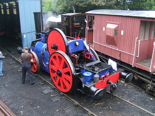 'Blue Circle' being prepared for service by Mick on the Battlefield Line in 2007.
The Large 'Single-wheeler' era ends
With the improvement in materials and production technology, it became possible to permit higher piston speeds with safety and the need for very large driving wheels declined. In this country, a driving wheel around 6 foot 8.5 inches diameter became the norm for fast running. Increasing train loads meant that a single driving axle was inadequate and 2, 3 or 4 axles would be coupled together. Again, the improvements in production techniques meant that the power losses originally associated with coupled wheels were acceptable.
Single Wheelers I've driven
'Rocket' replica
My first involvement with the 'Rocket' replica was at a Gala at Birmingham Railway Museum (late 1980s, I think) when I spent some time on the footplate with Ray Towell from the National Railway Museum. 'Rocket' visited the Museum of Science and Industry in Manchester (now Museum of Science and Industry) in 2005 and again in 2010 (celebrating 175 and 180 years, respectively, of the Liverpool and Manchester Railway). I managed to do a bit of driving and firing on both occasions. There's a little more about these events (with links to pictures) here.
'Planet' replica
When the 'Planet' replica was being built at the Museum of Science and Industry in Manchester, I was already a volunteer driver there. I did a few odd jobs during erection. I remember balancing on top of the boiler as the overhead crane lowered the tall chimney which I had to guide into its mounting flange on the smokebox.
In October 1992, there were lots of special steamings following the official launch. The locomotive went out on two sets of 'Trials', firstly at the Great Central Railway (at Loughborough) then to the East Lancashire Railway (at Bury). I was involved on both these visits and there's some information in the post The Planet Replica. We also made a visit to the National Railway Museum (at York) for a Gala, where we ran 'Planet' up and down on a special demonstration line without conveying passengers but I'm not sure of the date. 'Planet' did make a number of subsequent visits to other sites, although I wasn't personally involved in these. I was involved in driving 'Planet' at Manchester during the 175 and 180 year celebrations of the opening of the Liverpool and Manchester Railway and during the Transport Festival (and Great Garratt Gathering) in 2009. There's a little about the 175 and 180 year events here and a short report on the Transport Festival here.
I continued to drive in Manchester on the regular weekend service and a few special events (I well remember the Dalek Invasion in Manchester) until some time after 'Planet's' 21st birthday (described here).
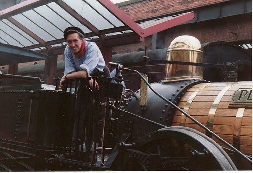 'Planet' replica (and a much younger Jan) at the original platform at Manchester some time in 1992-1993 (Photo: L. Walker, Wigan).
'Iron Duke' replica
When I was at York with the 'Planet' replica (mentioned above) the 'Rocket' replica was giving passenger rides on the standard gauge demonstration line and the 'Iron Duke' was giving passenger rides on the broad gauge demonstration line. They offered me a drive on either (not both) at the end of the public service. I elected for 'Iron Duke' which remains the only 7-foot gauge locomotive I've driven, although I've driven 5-foot 6-inch gauge in India (see the post My First Trip to India (continued)) and 5-foot gauge in Ukraine (see the post Ukraine 2005).
'The Blue Circle'
Mick, the owner of 'Blue Circle' has always encouraged my interest in his unusual motive power and one day he let me fire and drive up and down at Shackerstone on the Battlefield Line. It was an interesting experience!
 'Blue Circle' at Shackerstone in 2010: Driver's view.
Related articles on other sites
George Stephenson.
Robert Stephenson.
Related articles on this web site
Early Locomotive Design.
The Planet Replica.
'Planet' in Perspective.
Liverpool & Manchester 180th Celebrations.
'Planet' at MOSI - The First 21 Years.
Driving the 'Planet' replica.
Aveling & Porter Locomotive.
My pictures
Liverpool & Manchester 175th.
Liverpool & Manchester 180th.
Monday, 9 November 2015
Electrification Telephone Systems for British Rail
In the post Starting my own business I described setting-up a business and being awarded, in 1970, our first order for selective call telephone equipment from the London Midland region of British Rail. This equipment was for use in connection with the provision of new Power Signal Boxes at Warrington, Preston and Carlisle.
Electrification Telephone Systems for Crewe
Because the West Coast Main Line was being electrified at 25 kV 50 Hz, there was also a need for a separate system of 'Electrification Telephones' with its own, distinctively-marked weatherproof telephones connected back to the Electrical Control Room (ECR) located at Crewe. This control room, often called the 'Electric Control Room' or, more usually, just 'ECR' had been built by British Railways as part of the earlier Euston to Manchester Electrification Project. The ECR was located within what was then called Crewe District Electric Depot, on the down side of the Chester line, in between Crewe North Junction and Crewe Steel Works signal box.
When I returned to the site in 2008, the ECR was still there but the whole site had become Crewe International Electric Maintenance Depot (or Crewe IEMD) operated by E.W.S. See my report here.The 'Electrification Telephones' were placed at regular intervals along the route for use in the event of emergencies involving the Overhead Line Equipment (OLE). 'Electrification Telephones were also located at OLE outdoor switches and Track Section Cabins (TSC).
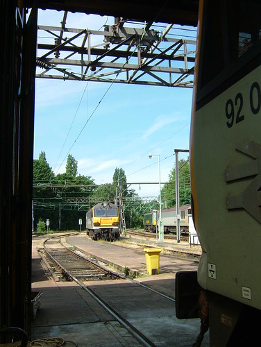
Crewe IEMD: View of the yard taken from within the depot in 2008.
In designing the original selective call equipment, we'd had to solve the problem of reducing the power consumption of the signalling decoder so that all the telephones on a circuit could be powered from the telephone line, eliminating the need for batteries at each telephone. But the requirements for the Electrification telephone system were harder to meet since it was also necessary that a number of telephones on the same circuit be able to join in the same conversation. This meant that we needed to reduce the power consumption of the speech circuit so that, when a call was in progress, the telephone line pair could supply power to a group of telephones engaged in the same conversation. After more development, we were satisfied that we could meet these requirements and tendered to the London Midland region of British Rail for a system covering 300 route-kilometres of electrified railway.
We won the tender and in 1971 were awarded the contract to supply Electrification telephones, repeaters, terminal racks and central operator consoles for use on the line from Weaver Junction (south of Warrington) to Carlisle. Production of this new order overlapped the first order for selective call telephone equipment which we'd started to work on in 1970.
Electrification Telephone Systems for Cathcart
The Electrical Control Room at Crewe was responsible for the line as far as Carlisle but electrification was being extended to Glasgow. There was a second Electrification Control Room at Cathcart, around three miles south of the centre of Glasgow. Later in 1971, we were invited to tender for the supply of a similar system for the Scottish Region of British Rail covering 200 route-kilometres of electrified railway controlled from Cathcart. We received the order for that system, too, so we were kept quite busy with three overlapping contracts for selective call telephone equipment.
The requirements for Cathcart included the supply of a Cord Switchboard - a manual switchboard with plugs and jacks to allow a number of calls to be routed simultaneously by the operator. Apparently, a number of earlier Electrical Control Rooms involved the use of a Cord Switchboard and it was a feature the client wanted to retain.
We still had plenty to learn about conventional telephony systems so another period of intense study was called for to enable us to work out how we could adapt a standard Cord Switchboard (designed to interconnect a number of Central Battery telephones to a group of outgoing junction circuits) to our selective call systems (designed to work with keyboards). My starting point, as always, was to consult the two volumes of the book 'Telephony' by J. Atkinson.
Back in the 1970s, there was no internet, of course (there's a splendid brief history of the internet by the Internet Society here). Today, you can research any topic with a few clicks and it's an amazing asset but conventional books are essential as well. There's a brief introduction to telephone switchboards on Wikipedia here but see also A manual telephone exchange: CBS2 on John Hearfield's good-natured and quirky site.
Plessey still made standard cord switchboards so we ordered one of those and, after some sleepless nights, came up with a design for a small sub-rack with reed relay interfaces mounted on plug-in circuit boards which we installed in the back of the switchboard.

A similar Cord Switchboard
(Photo: The Telephone Museum).
In general, British Rail performed their own installation and testing of our equipment but from time to time we were involved in visits to various sites to assist. Needless to say, I was always delighted to have an opportunity to poke about on a railway. However, for the Scottish Region project, whilst the railway were installing the telephones, they wanted us to install the cord switchboard and commission the whole system. Usually, two or three of us would fly up to Glasgow from Birmingham, we'd beaver away for a day then fly back. This was in the days of British European Airways (BEA) before they merged with BOAC in 1974 and became British Airways. Originally, they had Vickers 'Viscount' turbo-props on the route but later they were replaced by the Hawker-Siddeley 'Trident' with three Rolls-Royce 'Spey' jet engines.
I remember one trip when we took a huge, steel deed box as luggage. We'd crammed it with installation materials, tools and test equipment. It took two of us to move it but, to my surprise, the airline handled it without demur. No 'enhanced airport security' in those far-off, innocent days.
We managed to install and locally test the cord switchboard but Scottish Region were having problems completing their lineside cable system over which our telephones would operate so that we were delayed in completing commissioning. I began to understand their problems one day when, having been assured all was ready, we flew to Glasgow. On our arrival, they apologised and said that a section of recently-completed telecommunications cable had been stolen overnight and we'd thus have to postpone our testing. Apparently, they always made sure that cable was jointed the day it was laid, to discourage theft, but sometimes determined thieves would just hacksaw through the cable in a couple of places and carry away a section to 'scrap-in' for the copper. Live power cables were not immune from theft, they added. Perhaps not such innocent days, after all.
I'm pleased to confirm that, eventually, we were able to complete our commissioning.
Electrification Telephone Systems for Hornsey
In 1974, we received an order for one more system of Electrification Telephones for British Rail. This was for the Great Northern Electrification Project for the Eastern Region, covering 100 route-kilometres of electrified railway. This system was controlled from an Electrical Control Room at Hornsey, about four miles north of King's Cross, London. For this project, we supplied telephones with mounting plates plus repeaters, terminal racks and a Cord Switchboard (similar to that supplied for Cathcart). For this project, we also took responsibility for all installation and commissioning, including all the lineside telephones. Handling all aspects of installation gave a new dimension to this project and I'll write a little more when I can.
Wednesday, 4 November 2015
Starting my own business

The nameplate of the parent company Contactor Switchgear Limited (Photo: Wolverhampton History and Heritage Website).
With the arrogance of youth, I thought I could do a better job on my own. I decided to set up my own business, with encouragement from my wonderful mother who believed it better to try and fail than spend a lifetime regretting that I'd not made the attempt.
Well, there were some distinctly rocky times ahead but I've had some wonderful experiences and definitely made the right choice.
I started trading as 'J. C. Ford Consultant Electronics Engineer' during 1966. My mother had agreed to my using part of the family home (a modest terrace house) comprising the front room downstairs as an office, plus the cellar as a stores and workshop. For some years, the cellar had been virtually a 'no go' area and it was a major task cleaning it out, painting it and laying on better lighting. The worst part was the small adjunct forming a coal cellar. Although we no longer used coal, removing the evidence of a century's deliveries of solid fuel was rather daunting.
Things were very slow at first - nobody wanted to know. Everybody had told me to 'line up' work from contacts before I left employment but that didn't seem right to me, so I didn't. At first, the situation was rather bleak but, because I'd left my employer on good terms, after a while I was offered some sub-contract design and build work by them which helped a lot.
One of the most remarkable projects was the design and build for my former employers of a Ships Movement Indicator to be supplied to Dover Harbour Board. Because of the sheer size of the panels involved, for a few weeks we ended up taking over most of the living room as well as the office and cellar. Mealtimes became a very cramped affair.
Apart from sub-contract work for my previous employer, I managed to obtain some small industrial automation jobs in the local area. They were interesting, but not very profitable (come to think about it, an awful lot of contracts since have been like that).
An introduction to Gerry Gardner, a successful businessman and marvellous British eccentric, led to a change of pace. His company near Canterbury was bidding on a large contract for a Private Mobile Radio system for Lancashire Constabulary and he wanted us to design special digital selective call equipment for use with Philips VHF mobile radio equipment. Although Philips had their own selective call system, it didn't meet the requirements for the Police Network. In supporting the bid, I had my first ever flight, as described in the post here. Subsequently, I made a number of trips to Lancashire (travelling by land) for meetings or tests. It was a fascinating time, not least because the popular television show 'Z Cars' (which ran from 1962 to 1978) although set in the fictional town of 'Newtown' was actually based on Kirkby and Lancashire police. The comparison of fact and fiction was enthralling.

'Z Cars' Opening Title Logo
(Fair use claimed).
I was treated with great kindness by Gerry Gardner and often visited his headquarters which were in a large thatched barn next to his rambling, medieval home. Because of the success of the system for Lancashire Constabulary, we produced other systems for Fire Authorities and the Port of London Authority.
A few people I'd known at Contactor Switchgear (Electronics) Limited who had also moved on came to work with me and it was clear that I'd have to find alternative premises.
I'm afraid I made a rather odd choice, renting most of the former British Waterways canal depot in Broad Street, near the centre of Wolverhampton. This had originally been built for the canal carrying company of Fellows Morton and Clayton Ltd. There was a substantial two-storey brick warehouse building with offices, ground floor warehouse (including an internal canal basin!) and an upper floor warehouse reached via a wonderful spiral staircase. One wing of this building was retained by British Waterways Board as their local Estates Office. In the yard there was a toilet block and a small two-storey building which was already let to an elderly man who made canvas shop blinds. The business had originally made and repaired the large canvas sheets used by freight-carrying narrow boats. The accommodation was completed by a fairly modern 3,000 square foot steel-framed warehouse clad in corrugated cement asbestos sheeting. Finally, there was an outside canal basin.
Needless to say, charming as the property was, it was not particularly suitable for manufacturing electronics equipment. The site was huge compared with our immediate needs but I'd taken the precaution of ensuring that we could sub-let space we didn't need. I suppose the steel-framed building would have been easiest to adapt for our use, but we'd already had interest from a steel fabricating firm in renting that building and soon concluded a letting agreement with them. Rather later, a small mechanical engineering firm rented part of the upper floor of the main warehouse.
For our own needs, partitions and ceilings were erected in part of the ground floor warehouse to provide stores and production areas. At about this time, my former employers had decided to 'slim-down' their electronics operation, resulting in their maintenance manager disposing of a quantity of second-hand workbenches, chairs, shelving units and partitions. Unexpectedly, he offered to sell them to me at very reasonable prices and they proved invaluable in moving into our new home.
 The upper part of the main building at Broad Street Depot, as seen from the adjacent railway station in 2013.
In 1970, British Rail approached us about the possible supply of selective call telephone equipment for the electrification between Crewe and Carlisle. Having produced successful systems for use over radio, in my ignorance I imagined that a similar system for use on telephone circuits would present little challenge. A steep learning curve followed as we grappled with the special problems of line communications.
The railways had previously used a system from Plessey which used mechanically resonant reeds to detect a specific calling frequency. Disadvantages were that each telephone installation needed a different resonant reed and its own battery power supply. In addition, when used outside, a large weatherproof housing was required to mount the batteries, the control unit and the telephone instrument.
The Post Office (which wasn't privatised as British Telecommunications until 1981) had approved a weatherproof wall telephone made by Plessey generally referred to as the '745' (there's information on this telephone here).
Our design aim was to cram everything inside this telephone instrument, provided that we could reduce power consumption sufficiently to allow the telephone to be line powered using a variation on established Central Battery techniques. A small number of voice frequencies transmitted as a sequence of tones would allow a single type of selective call decoder to be configured (on site, if necessary) to respond to any desired code. The proposed technique offered the possibility of significant economies. Just when we'd solved the technical problems, we were hit from another direction - component supply problems. I've written about this in the post If it were easy, everyone would do it.
We won the contract with our innovative approach and were kept busy over the next three years building the required equipment in connection with the Power Signal Boxes being installed at Warrington, Preston and Carlisle covering 400 route-kilometres of railway. We supplied our 'C.B. Selective' telephone equipment complete with repeaters, terminal racks, spares, maintenance equipment and training services.
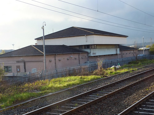 Warrington Power Signal Box, pictured in 2012.
More.
Friday, 30 October 2015
The Battlefield Line Steam Gala
On the Sunday, I was 'marked' to drive visiting 'Austerity' 0-6-0ST locomotive 'Cumbria'. There's more information about 'Cumbria' on the Furness Railway Trust Site here. I turned up early as 'Cumbria' and 'Sir Gomer' were booked to double-head a demonstration freight train departing Shackerstone at 08:45. I found 'Cumbria' and 'Sir Gomer' outside the shed, coupled together bunker to bunker. The fire in 'Cumbria' was being lit so I set about oiling round. Fortunately, 'Cumbria' is in 'as-built' state without mechanical lubricators on the framing and the mechanical drive that necessitates so access was not a problem and I was able to climb into the motion to attend to the eccentrics and big ends without difficulty. I've lamented before that I find the other 'Austerity Tank' I drive fairly regularly, 'Lord Phil' at Peak Rail, difficult to prepare because of the 'modernisation'.
Both engines were in steam in plenty of time but both engines needed to take water and Danny said we'd need coal after our freight train run. So, coupled together, the two engines trundled over to the water column on platform 2 road. We stopped so that 'Sir Gomer' could take water first and whilst he took water, we uncoupled. Because the freight train was stabled in the DMU siding, we had a bit of a shunt to undertake. 'Sir Gomer' went across to the DMU siding, attached the double-braked freight train and drew the whole train down to the North End, clear of the crossover to the single line. Meanwhile, we took water and Phil, the signalman, loosed us to the Section Signal. With the crossover reversed, 'Sir Gomer' propelled the whole train onto us, with Danny "on the floor" giving hand signals to Brian on 'Sir Gomer'.
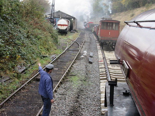 With Danny controlling the move, 'Sir Gomer' propels the freight train onto waiting 'Cumbria'.
The goods train was coupled to us, uncoupled from 'Sir Gomer' and, with the crossover set normal again, 'Sir Gomer' moved north along platform 2 road, clear of the crossover. With the crossover reversed again, we then propelled the freight into platform 1. Finally, 'Sir Gomer' came across and coupled "on top of us".
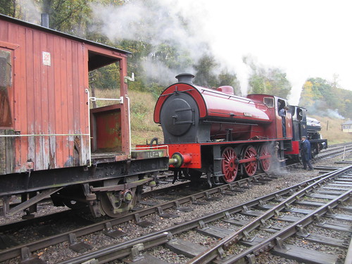 'Cumbria' and 'Sir Gomer' ready to leave Shackerstone with the 08:45 freight.
Once the Guard had arrived and checked the train, we were "Right Away" on time with Danny supervising firing by the cleaner, Jacob. As we passed the signal box, the signalman, Phil, showed the Single Line Staff to 'Sir Gomer' but handed it to me. In steam days, it was always the rearmost locomotive which carried the Staff.
Peak Rail has reversed this tradition so, when top-and-tailing there, it's the leading engine which carries the Staff.We made a slow departure - the limit is 5 m.p.h. over the crossover from platform 1, Dead Slow over the relaid track panels, then 10 m.p.h. up the bank until clear of the Barton Lane road bridge. We then picked up a bit of speed. At the two foot crossings, there are 'W' boards ('Whistle') and 'Sir Gomer' complied. In this area, there was a group of photographers trackside but there were various people waiting for us to pass at various places down the line.
 A group of photographers capture the 08:45 freight.
As you approach Market Bosworth there's an 'SW' board ('Sound Whistle' - I think the Great Western originally preferred this formulation) but 'Sir Gomer' didn't whistle. Then Danny shouted "Whistle!", so I did. It appeared that 'Sir Gomer's' whistle chain had become detached, leaving the engine mute. Although we were not booked to stop, Brian brought the train to a stand in the platform so that a whistle repair could be effected and, when the Guard gave the 'tip', both engines whistled and we set off for Shenton. For some time, there had been a 15 m.p.h. slack passing over the bridge near the south end siding, but this had recently been downgraded to a 5 m.p.h. limit. Once clear of this, we were able to hustle on to Shenton.
Leaving the two engines coupled together, we ran round our double-braked train (that is, a brake van on each end), so we didn't have to do the extra shunt which would have been needed to get a single brake van onto the other end of its train.
This used to be a question for shunters - simple loop, one engine, set of wagons, one brake van, what are the moves?Having used the Single Line Staff to work the points for us at the Shackerstone end of the loop, the Guard showed the staff to me, as I was now the leading engine, but handed it to 'Sir Gomer'. As soon as the Guard was "back in his box" at the rear of the train, he gave the "Right Away". Once we were clear of the speed restriction in Shenton Station, I was able to open 'Cumbria' up a little.
The arriving train stops with the brake van just outside the loop points. Van brake is applied and brake van is uncoupled. Engine draws wagons into station and sufficient wagon handbrakes are applied before engine uncouples, draws forward to headshunt, reverses round the loop to the brake van, attaches it and takes it forward round the loop to the headshunt, then propels the brake onto the waiting wagons. Brake van is attached to wagons, brakes set as required, engine uncouples, forward into headshunt, reverse around the loop until outside the loop points which are then set towards the wagons. Finally, engine moves forward onto the wagons. Job done!
We found her a rather noisy engine. Both injectors were very loud (and the one on the fireman's side wasted a lot of water). In full first valve with the gear notched up one notch (she went a bit 'off-beat' on two notches), there was a loud roar from the chimney - a mixture of the expected four discharges per revolution of the wheels and a continuous noise, possibly turbulence caused by the vacuum ejector or misalignment of the blast pipe. At least the row drowned out the occasional thumps and bangs from the axleboxes and big ends. But, having said that, she gamely hauled our train back to Shackerstone, where we arrived about 'right time'. We cautiously made our way into platform 1, passing the 'Collett Goods' which had 'hooked on' to the 4-coach Griddle Car set in platform 2, ready to work the ten o'clock departure.
We uncoupled from 'Sir Gomer', leaving Brian to propel our train back through platform 1 and stable it in the DMU siding, whilst we kept out of the way on the 'back road' at the north end. 'Sir Gomer' returned, picked up the 4-coach 'Set 2' from the 'front road' at the north end and positioned it in platform 1 ready for the eleven o'clock hauled by 'Dinmore Manor'. Once the coaching stock was removed, we were able to shunt across to the 'front road' to await coaling, after which there was time for a bit of breakfast before our next duty.
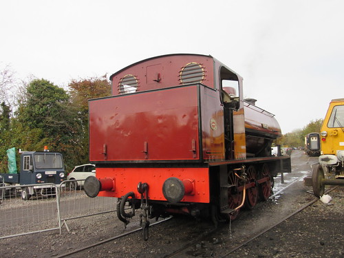 3794 'Cumbria' awaiting coaling.
Passenger trains were booked to depart Shackerstone hourly. The 'Collett Goods' was back in good time and enthusiasts scuttled across from the train they'd just arrived on to platform 1 for another trip down the line on the eleven o'clock departure. Once 'Dinmore Manor' had left with its train, we were able to shunt via platform 1 to couple onto the head of the 'Griddle Car Set' in platform 2 ready to work the 12 o'clock.
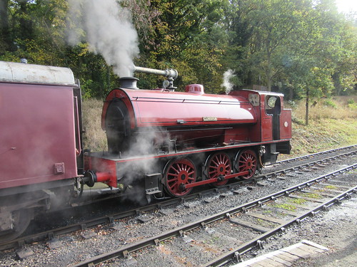 'Cumbria' ready to take the 12 o'clock departure.
We were a little late away. Although we had a good run down to Shenton, we were still a couple of minutes late at Shenton, as the Guard pointed out. We ran round smartly and had another good run back to Shackerstone, this time, of course, chimney leading and ran into platform 2 about right time. The 'Collett Goods' was ready to take the one o'clock out of platform 1 and, when that departure had left, 'Dinmore Manor' was able to take her place at the other end of the train we'd brought in.
Dinmore Manor was first restored to traffic in 1995 at Tyseley Locomotive Works. When she was first steamed, they were keen to try her out looking for any problems before she left Birmingham, and I was fortunate enough to have her for a few hours whilst we ran up and down the demonstration line continuously. I'd been told that, to celebrate the event, I could allow Museum Volunteers to have a footplate ride on this "fresh off" (the term for a locomotive emerging from the works after overhaul) and it was a very jolly time. Then, she was in green livery but she now sports unlined black with the original British Railways insignia on the tender, affectionately called 'the Lion astride a Mangle-wheel'. There's more about the '7800' class here and more about the preservation group which owns 'Dinmore Manor' here.
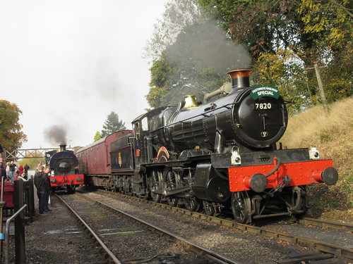 'Sir Gomer' stands in platform 1 and 7820 'Dinmore Manor' waits to take the two o'clock from platform 2.
The 'Collett Goods', working tender first, arrived back in platform 1 in plenty of time to allow the 2 o'clock to leave 'right time'.
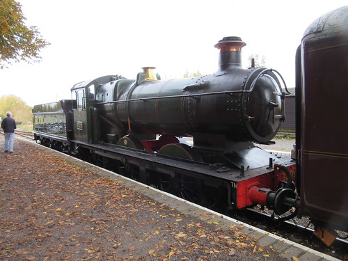 3205 Collett Goods, having left with the one o'clock is back before 2 o'clock.
We then had plenty of time to take water again and couple onto the stock in platform 1. When 'Dinmore Manor' arrived back, we "got the road" for the 3 o'clock departure and, receiving the "Right Away" from the Guard, we set off on our last round trip of the day.
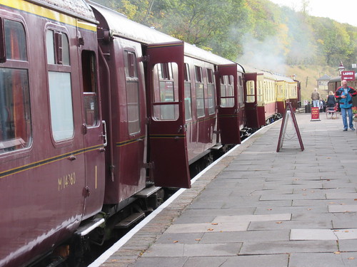 'Set 2' coaches in platform 1, with 'Cumbria' just visible at the far end, ready to take the 3 o'clock train.
We had another pleasant trip, although some doubts started to be expressed as to whether we should have taken on a little more coal. You often hear talk of "sweeping the tender out" to get home and sometimes it's true. The picture below shows Jacob sweeping out our bunker. When we arrived back in platform 1 at Shackerstone, 3205 and 7820 were ready to double-head the last train of the day from platform 2.

Jacob sweeping out the bunker.
'Sir Gomer' had already disposed and moved into the shed so we knew we would have to shunt our train out of the way ourselves. After the 4 o'clock had left, we were able to run round our train using platform 2, couple onto the stock and create vacuum. Since this would be a propelling move, Danny moved to the head of the movement, to keep a look-out and give handsignals. Because of the line curvature, these handsignals were given on the left of the train to Jacob on the fireman's side of the footplate and he relayed them to me. We couldn't move the stock quite as far as we'd hoped because somebody had parked a Land Rover across the siding. Once the handbrake had been applied to the train, we uncoupled and scuttled off to the shed.
Danny had judged matters to perfection. Whilst we'd had adequate steam to complete the shunt in safety (as boiler pressure falls, the effectiveness of the locomotive steam brake is reduced) with enough steam left to fill the boiler (using the 'best' of the two injectors), there was very little fire left to require 'cleaning' and little clinker. The boiler could be left to cool naturally, minimising the stresses and reducing the chances of creating leaking tubes and stays.
The day had been dry and I understand passenger numbers had been healthy. All-in-all, an interesting and satisfying day.
Related posts on this site
'Sir Gomer'
The 'Austerity' 0-6-0ST locomotive.
All my Battlefield Line posts.
My Pictures
Battlefield Line Steam Gala, October 2015
All my Battlefield Line pictures.
[Moves in connection with coaling corrected: 4-Nov-2015]
Thursday, 29 October 2015
Double Wire Working of Points and Signals
Railway signalling in Britain was originally based on the operation of 2-aspect semaphore signals by a single wire and operation of points using rodding. This blog has an (incomplete) series of articles about these techniques, starting at Railway Signalling in Britain: Part 1: Introduction.
In continental Europe and its export markets, a completely different approach developed using double wires kept under tension to control each semaphore signal and each set of points. This technique was usually employed with a type of lever frame described as 'Turnover'.
The double wire approach conferred some advantages, most importantly allowing points to be operated at greater distances from the signal box than using rodding and allowing semaphore signals provided one or two arms to be controlled from one double wire. A further potential advantage compared with single-wire operation of signals is that, with single wire operation, the first part of the lever movement may be 'wasted' in taking up the slack. Similarly, if the bell cranks in point rodding runs become worn, that results in 'lost motion' of the lever. Because both wires in the double-wire approach are maintained in tension by Compensators, 'lost motion' is eliminated.
There's an excellent 'primer', written in 2004 by Dr James B. Calvert, here.
The 1932 book ‘Lewis’s Railway Signal Engineering (Mechanical)’ (book reference [1] below) has a chapter on Double Wire Working which you can read here.
Details of design and signal aspects displayed vary from country to country. The paragraph below applies to Poland.
Signal arms project to the right of the post (rather than to the left as in Britain) and arms have a distinctive shape and colouring.Thailand
In a signal provided with one arm (often used for 'starting' or 'departure' signals) the arm stands horizontal for 'stop' and is raised to an angle of 45 degrees for 'proceed'.
In a signal provided with two arms (often used for 'home' or 'entrance' signals) the upper arm stands horizontal and the lower arm stands vertical for 'stop'. 'Proceed at line speed' is indicated by raising the upper arm to an angle of 45 degrees and maintaining the lower arm vertical. 'Proceed at reduced speed' (for instance, entering a loop line) is indicated by raising the upper arm to an angle of 45 degrees and lowering the lower arm to an angle of 45 degrees.
At night, coloured lights are displayed through moveable spectacles.
My first experience of double wire working of points and signals was when my firm supplied equipment for a Train Despatcher system in Thailand. I made a number of visits to the country during the installation and commissioning phase. Most of the signalling installations were double wire, controlled from distinctive Turnover Frames. At one signal box (Hua Hin, I think), the smiling signalman let me work the frame between trains to my heart's content. I was fascinated with levers which turn through 180 degrees, where the tip of the lever is moved through an arc of over seven feet. Viewed from the left of the frame, the lever arc is from about "11 o'clock" to "5 o'clock" Having been brought up on Mr. Webb's frames for the London and North Western Railway with 'hoop' catch handles, I found Turnover Frames very odd. Having pulled the lever to about the "2 o'clock" position, you then need to reverse your grip on the handle so that you can push it down to the "5 o'clock" position. The signals were of the 'German' upper quadrant pattern, common in Europe and further afield, where the signal post and arm design is very different from British practice and, most confusingly, when viewed from the front, signal arms extend to the right of the post.
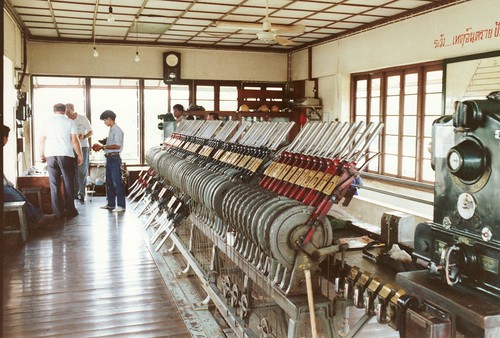 A Signalbox with a large Turnover Lever Frame.
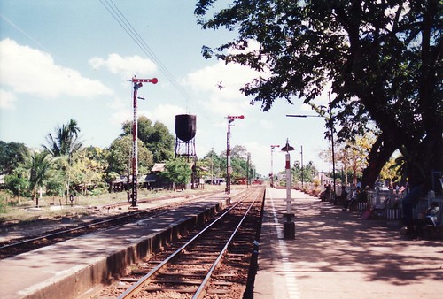 Three semaphore 'starting' signals at a wayside station.
After the Train Despatcher project was completed in 1989, I returned to Bangkok to assist in setting up Bangkok Railway Museum and I arranged for a small Turnover Frame to be exhibited, along with a pair of Electric Token machines, representing a wayside station. There's a short post about the setting up of the Bangkok Railway Museum here, with links to pictures.
Poland
In 2003 I accompanied my friend Mike to Poland for steam locomotive driving on 'The Wolsztyn Experience', briefly described here. Out in the country, most signals were semaphore of the 'German' pattern, although colour-lights prevailed where we joined the main lines at Posnan, Zybasyn and Lesno. I was able to have a good look at the turnover frame at one of Wolsztyn's two signalboxes.
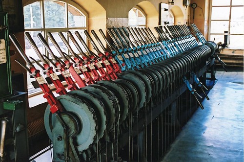 Wolsztyn Signalbox: Detail of Turnover Lever Frame.
 A row of semaphore signals at Wolsztyn. The black metal box displaying a diagonal white marking is a mechanical point indicator.
Indonesia
Visiting Yogyakarta, Java in 2010, I made a brief visit to Maguwo station which has semaphore signals and points controlled using the double wire system from a turnover frame. Signals were similar to the 'German' pattern but the arc of the levers in the Turnover Frame (viewed from the left) was restricted, extending from "12 o'clock' to "5 o'clock". There's a brief report here.

Part of the Turnover Frame at Maguwo, Indonesia.
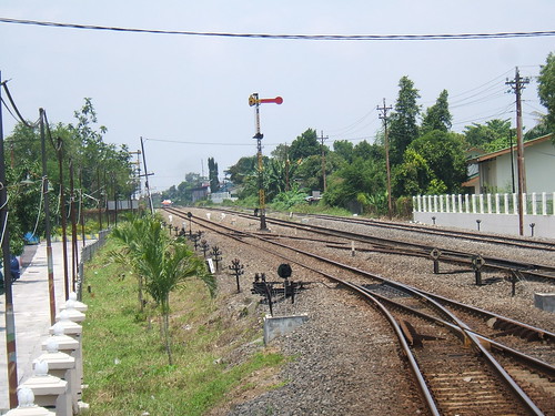 Maguwo: Single arm 'starting' signal with two arm 'home signal' just visible left background. Note the point indicators and point/signal wires carried on pulleys
Russia
On my trips to Russia, I only found colour light signals in use but at the Rolling Stock Museum, Novosibirsk (which I visited in 2012 as part of a trip from Ulaan Baatar to Moscow, described here), I found a very Germanic-looking 2-arm 'Entrance' signal with a Signal Cam Wheel mounted on the post.
 Click on image for larger view
Upper part of a 2-arm home signal, showing the post-mounted Signal Cam Wheel operating both arms through push rods.
Vietnam
On my second visit to Vietnam as part of my 'Far East 6' trip in 2013 (described here), I was able to see a little more of the railways which mainly feature colour light signals. But in places I found semaphore, double-wire operated signals, as shown below. However, these were lower quadrant arms, extending to the left of the post. The front of the arms was red and white and they would have looked almost British, apart from generally having two 'stop' arms, one of which was usually hanging straight down. I presume turnover frames controlled these mechanical installations but I didn't have an opportunity to confirm this.
 Click on image for larger view
Lower arm of a 2-arm 'Entrance' signal, showing the post-mounted Signal Cam Wheel operating both arms through push rods.
China
In 2013, I travelled to Tibet by train from China: the journey is described in the post Travelling on the Qinghai - Tibet Railway. As expected, all the railway signals were colour light. Then I had a couple of days in Shanghai and, in Shanghai Railway Museum, I found a 2-arm semaphore signal similar in appearance to those in use in Vietnam. However, the Chinese example had two escapement mechanisms near the base of the post rather than a conventional Signal Cam wheel so I'm not certain it was intended for double wire operation.
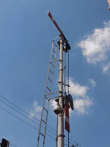
A preserved 2-arm 'home' signal from the Tai Yuan Railway Administration, now on display at Shanghai Railway Museum (complete with CCTV camera).
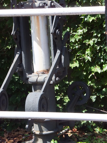
Detail of escapement mechanism at the base of the post.
Britain
The Board of Trade did not permit operation of points using rodding which were more than 350 yards from the controlling lever frame. The use of double-wire operation of points was not authorised until 1925, after which a few installations were made, either as complete turnover frames or simply as a short extension to a conventional lever frame.
Rowsley Down Sidings had one of the early LMS non-interlocked turnover frames - a rather crude affair where a counterweight near the end of each lever held it 'normal' or 'reverse'. In this design, the arc of the levers in the frame (viewed from the left) was from "10 o'clock' to "3 o'clock". There's a picture on Dominic Beglin's page Old Pictures Part 1. The LMS then produced a more refined frame design called the 'LMS New pattern Turnover Frame'. There's a description of some of the LMS double-wire initiatives on Dave Harris's Derby Signalling Web Site page Cottage Lane Crossing. Barrow Hill Up Sidings Box also used this pattern frame and there are more details on the indispensible site 'The Signal Box' here. When Barrow Hill Up Sidings Box was abolished, its Turnover Frame was preserved by the National Railway Museum. Apparently, both the Great Western Railway and the London & North Eastern Railway Railway had a few Turnover Frames.
Peak Rail
Peak Rail have a project in hand to install a Midland-pattern signal box at the present northern terminus, Rowsley, to control the points at the north end of the station. This will feature double-wire operation from a frame of the 'LMS New pattern Turnover' design (part of the Barrow Hill Up Sidings Turnover Frame mentioned above) housed in the structure from Bamford Signalbox (relocated again). Progress on this project is shown on Dominic Beglin's page Latest Project News. There's also a discussion thread on 'The Signal Box' site here.
Related articles on other sites
Two-Wire Transmission.
Double Wire installations in Australia (A very detailed article by Andrew Waugh).
The Signal Page (Information on signalling practice in many countries).
Book references
[1] ‘Lewis’s Railway Signal Engineering (Mechanical)’ revised and enlarged by J H. Fraser (Constable & Company Ltd. 3rd edition 1932).
[2] 'Modern Railway Signalling' by Tweedie and Lascelles (Blackie and Son Ltd 1925).
My pictures
Railways in Thailand (1989).
Polish Railways (PKP).
Java: Maguwo Station.
Railways in Vietnam.
Shanghai Railway Museum.