skip to main |
skip to sidebar
History
The first tunnel under the River Mersey was a railway tunnel. The authorising act of 1866 was for the Mersey Pneumatic Railway but investors were chary of such a novel concept and progress was not made until James Brunlees took over in 1870. He changed the name to the Mersey Railway, envisaging a conventional underground railway operated by steam locomotives. With gradients as severe as 1 in 27, it was still a challenging line.
Work started in 1879 and continued for a number of years. During the tunnel construction phase, 'Scientific American' published an upbeat review of progress and, through the work of Project Gutenberg, this contemporary account appears below.
 NO. 384, NEW YORK, MAY 12, 1883
THE MERSEY RAILWAY TUNNEL.
The work of connecting Liverpool with Birkenhead by means of a railway tunnel is now an almost certain success. It is probable that the entire cost of the tunnel works will amount to about half a million sterling. The first step was taken about three years ago, when shafts were sunk simultaneously on both sides of the Mersey. The engineers intrusted with the plans were Messrs. Brunlees & Fox, and they have now as their resident representative Mr. A.H. Irvine, C.E. The contractor for the entire work is Mr. John Waddell, and his lieutenant in charge at both sides of the river is Mr. James Prentice. The post of mechanical engineer at the works is filled by Mr. George Ginty. Under these chiefs, a small army of nearly 700 workmen are now employed night and day at both sides of the river in carrying out the tunnel to completion. On the Birkenhead side, the landward excavations have reached a point immediately under Hamilton Square, where Mr. John Laird's statue is placed, and here there will be an underground station, the last before crossing the river, the length of which will be about 400 feet, with up and down platforms. Riverward on the Cheshire side, the excavators have tunneled to a point considerably beyond the line of the Woodside Stage; while the Lancashire portion of the subterranean work now extends to St. George's Church, at the top of Lord street, on the one side, and Merseyward to upward of 90 feet beyond the quay wall, and nearly to the deepest part of the river.
When completed, the total length of the tunnel will be three miles one furlong, the distance from wall to wall at each side of the Mersey being about three-quarters of a mile. The underground terminus will be about Church street and Waterloo place, in the immediate neighborhood of the Central Station, and the tunnel will proceed from thence, in an almost direct line, under Lord street and James street; while on the south side of the river it will be constructed from a junction at Union street between the London and Northwestern and Great Western Railways, under Chamberlain street, Green lane, the Gas Works, Borough road, across the Haymarket and Hamilton street, and Hamilton square.
Drainage headings, not of the same size of bore as the part of the railway tunnel which will be in actual use, but indispensable as a means of enabling the railway to be worked, will act as reservoirs into which the water from the main tunnel will be drained and run off to both sides of the Mersey, where gigantic pumps of great power and draught will bring the accumulating water to the surface of the earth, from whence it will be run off into the river. The excavations of these drainage headings at the present time extend about one hundred yards beyond the main tunnel works at each side of the river. The drainage shafts are sunk to a depth of 180 feet, and are below the lowest point of the tunnel, which is drained into them. Each drainage shaft is supplied with two pumping sets, consisting of four pumps, viz., two of 20 in. diameter, and two of 30 in. diameter. These pumps are capable of discharging from the Liverpool shafts 6,100 gallons per minute, and from the Birkenhead 5,040 gallons per minute; and as these pumps will be required for the permanent draining of the tunnel, they are constructed in the most solid and substantial manner. They are worked by compound engines made by Hathorn, Davey & Co., of Leeds, and are supplied with six steel boilers by Daniel Adamson & Co., of Dukinfield, near Manchester.
In addition to the above, there is in course of construction still more powerful pumps of 40 in. diameter, which will provide against contingencies, and prevent delay in case of a breakdown such as occurred lately on the Liverpool side of the works. The nature of the rock is the new red sandstone, of a solid and compact character, favorable for tunneling, and yielding only a moderate quantity of water. The engineers have been enabled to arrange the levels to give a minimum thickness of 25 ft. and an average thickness of 30 ft. above the crown of the tunnel.
Barges are now employed in the river for the purpose of ascertaining the depth of the water, and the nature of the bottom of the river. It is satisfactory to find that the rock on the Liverpool side, as the heading is advanced under the river, contains less and less water, and this the engineers are inclined to attribute to the thick bed of stiff bowlder clay which overlies the rock on this side, which acts as a kind of "overcoat" to the "under garments." The depth of the water in one part of the river is found to be about 72 ft.; in the middle about 90 ft.; and as there is an intermediate depth of rock of about 27 ft., the distance is upward of 100 ft. from the surface of low water to the top of the tunnel.
It is expected that the work will shortly be pushed forward at a much greater speed than has hitherto been the case, for in place of the miner's pick and shovel, which advanced at the rate of about ten yards per week, a machine known as the Beaumont boring machine will be brought into requisition in the course of a day or two, and it is expected to carry on the work at the rate of fifty yards per week, so that this year it may be possible to walk through the drainage heading from Liverpool to Birkenhead. The main tunnel works now in progress will probably be completed and trains running in the course of 18 months or two years.
The workmen are taken down the shaft by which the debris is hoisted, ten feet in diameter, and when the visitor arrives at the bottom he finds himself in quite a bright light, thanks to the Hammond electric light, worked by the Brush machine, which is now in use in the tunnel on both sides of the river. The depth of the pumping shaft is 170 feet, and the shaft communicates directly with the drainage heading. This circular heading now has been advanced about 737 yards. The heading is 7 feet in diameter, and the amount of it under the river is upward of 200 yards on each side. The main tunnel, which is 26 feet wide and 21 feet high, has also made considerable progress at both the Liverpool and Birkenhead ends. From the Liverpool side the tunnel now extends over 430 yards, and from the opposite shore about 590 yards. This includes the underground stations, each of which is 400 feet long, 51 feet wide, and 32 feet high. Although the main tunnel has not made quite the same progress between the shafts as the drainage heading, it is only about 100 yards behind it. When completed, the tunnel will be about a mile in length from shaft to shaft. In the course of the excavations which have been so far carried out, about 70 cubic yards of rock have been turned out for every yard forward.
Ten horses are employed on the Birkenhead side for drawing wagons loaded with debris to the shaft, which, on being hoisted, is tipped into the carts and taken for deposit to various places, some of which are about three miles distant. The tunnel is lined throughout with very solid brickwork, some of which is, 18 inches thick (composed of two layers of blue and two of red brick), and toward the river this brickwork is increased to a thickness of six rings of bricks--three blue and three red. A layer of Portland cement of considerable thickness also gives increased stability to the brick lining and other portions of the tunnel, and the whole of the flooring will be bricked. There are about 22 yards of brickwork in every yard forward. The work of excavation up to the present time has been done by blasting (tonite being employed for this purpose), and by the use of the pick and shovel. At every 45 ft. on alternate sides niches of 18 in. depth are placed for the safety of platelayers. The form of the tunnel is semicircular, the arch having a 13 ft. radius, the side walls a 25 ft. radius, and the base a 40 ft. radius.
Fortunately not a single life has up to the present time been lost in carrying out the exceedingly elaborate and gigantic work, and this immunity from accident is largely owing to the care and skill which are manifested by the heads of the various departments. The Mersey Tunnel scheme may now be looked upon as an accomplished work, and there is little doubt its value as a commercial medium will be speedily and fully appreciated upon completion.
Beyer Peacock supplied massive 0-6-4T condensing locomotives to operate the Mersey Railway and the line finally opened in 1886, but conditions in the tunnel for passengers (let alone enginemen) were atrocious. The railway was soon in financial difficulties and receivers were appointed in 1887. The financial situation was improved in 1888 by the connection of the tunnel lines to the Wirral Railway, producing a proper suburban network extending to Wallasey and New Brighton. However, despite the provision of steam driven fans (the largest 40 feet in diameter!) intended to keep the tunnels clear, steam traction only lasted until 1903 when, to the relief of everyone concerned, electric traction took over. The three books in the 'References' section below have further information about the Mersey Railway.
The picture below shows one of the condensing locomotives, clarifying the operation of the condensing facility. A large slide valve, fixed to the side of the smokebox, was provided in the exhaust from each cylinder. A control rod from the footplate either diverted the exhaust into the smokebox (when working above-ground) or into the side tank (when in the tunnel). An inverted U-shaped pipe linked the two side tanks and vented air (or uncondensed steam). Note that, in the present 'Cecil Raikes', each side tank has a separate vent.
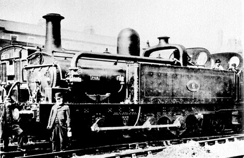 Locomotive No. 6 'Fox' in service (Photo: 'The Pictorial Encyclopedia of Railways' by Hamilton Ellis, published by Paul Hamlyn, 1968).
Following electrification, the redundant steam locomotives were sold off. In 1904 locomotive No. 5, 'Cecil Raikes', was sold to Shipley Colliery in Derbyshire in 1904, where it worked for the next fifty years. Then followed some years in storage at Derby Locomotive Works before British Railways Board presented the locomotive to National Museums Liverpool in 1965.
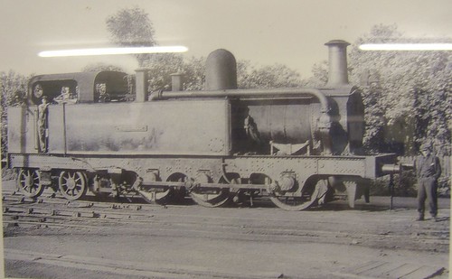 'Cecil Raikes' in colliery service at Shipley.
Since the Museums had no suitable way of displaying the locomotive, it was placed on loan and displayed at Southport Steam Centre ('Steamport') which occupied the disused British Railways steam shed at Southport.
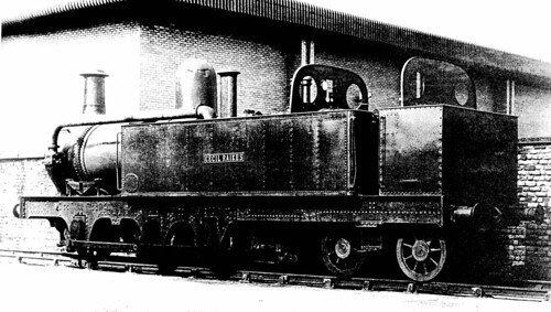 'Cecil Raikes' at the Southport Steam Centre (Photo: Southport Steam Centre).
This is where I first saw 'Cecil Raikes' in the 1980s. The 'Steamport' operation subsequently relocated to Preston as The Ribble Steam Railway and 'Cecil Raikes' returned to Liverpool Museums and was again placed in store.
I next saw the locomotive in 2010, as I described in my post here. The museum staff allowed me to take a series of pictures.
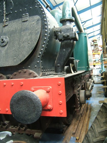
There was little space to frame the shot but this perhaps gives an idea of of the size of this powerful 0-6-4T.
Articles on other websites
See Wikipedia article here.
See also Liverpool's Historic Rail Tunnels
Book References
[1] 'The Line Beneath The Liners: A hundred years of Mersey Railway sights and sounds' by John W. Gahan, published by Countyvise (ISBN 0 907768 40 7 and Avon AngliA Publications (0 905466 57 8).
[2] 'An Illustrated History of Liverpool's Railways' by Paul Anderson, published Irwell Press (ISBN 1-871608-68-6).
[3] 'British Railway History - An outline from the Accession of William IV to the Nationalisation of Railways, 1877-1947' by Hamilton Ellis, published by George Allen and Unwin, 1959.
My pictures
Profile - 'Cecil Raikes'.
[Revised 10-Oct-2013 - picture of 'Fox' added]
On Sunday 29th September 2013 I was rostered as Steam Driver at Peak Rail with Mike as fireman. Once again, we were operating top-and-tail with a seven coach rake (including the 'Exhibition Coach', a converted 'BG' bogie brake with a display of photographs outlining volunteer activities as a 'recruiting tool') and the Class 31. Mike and I were on the south end of the train with 'Lord Phil' facing Matlock and the Class 31 was on the north end.
We had a one-hour 'Driving Experience' course prior to the public service, so we came 'off shed' at Rowsley at 09:15 and made our way light engine to Darley Dale to be ready for our trainee, Mr. Stone, at 09:45. We spent the next hour trundling between Darley Dale (south of the Down Home signal) and Matlock Riverside (north of the River Derwent bridge). At 10:45, we left our trainee at Darley Dale and scuttled 'light engine' to Rowsley to pick up our train.
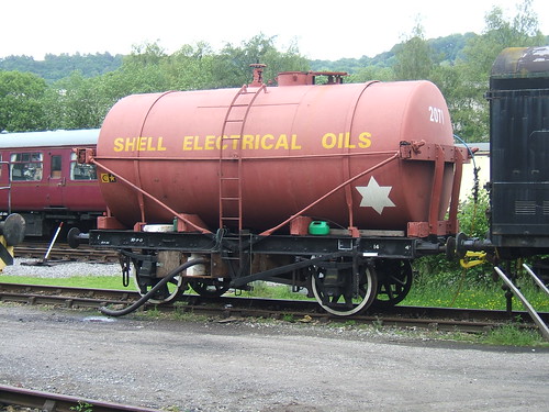
The Guard called us onto the coaches, Mike coupled-up and together we replenished the saddle tank. Taking water at the south end of Rowsley station is a bit tedious at present. A 4-wheel tank wagon is parked on an adjacent siding and filled from a water main via a ball valve fitted in the top of the tank. The water tank is connected to a portable water pump driven by a petrol engine. The water pump discharges through a long canvas fire hose which has to be dragged across to the steam locomotive and lifted up to the top of the saddle tank and secured inside the tank filler. We normally repeat this process two more times during the day.
 The nicely-restored 'Shell Electrical Oils' tank wagon used as a water tank at the south end of Rowsley station.
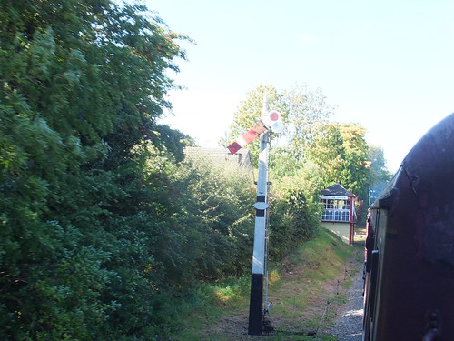
We operated the usual five round trip service, hauling each train to Matlock (Town) and then suffering the indignity of being dragged backward to Rowsley by the Class 31. The picture below shows us passing Church Lane signal box on the way to Rowsley whilst being pulled by the Class 31.
 Passing Church Lane, with a good view of the Midland Railway lower-quadrant signal in the 'Off' position.
The 'Palatine' Dining Train boarded diners on the 12:31 departure from Rowsley and we met up with our trainee again as he was dining on the train with his family to complete 'The Peak Rail Experience'.
The Derbyshire Dales Narrow Gauge Railway was running as a further attraction. I've written briefly about this railway here, with a link to my pictures.
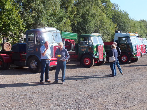
The Limestone Run is a once-a-year run of about 100 miles around the Peak District for Vintage Commercial Vehicles. In 2013, it was held on 29th September, starting at Belper and terminating in the afternoon at Peak Rail, Rowsley. There are a couple of pictures below taken from my Set Vintage Commercial Vehicles at Peak Rail. You can find more pictures on Facebook here. We were very lucky with the weather and it was another good day.
 Drivers relax having completed the Limestone Run.
 Later in the afternoon, the yard had filled up with preserved vehicles.
My pictures
'Lord Phil'.
Vintage Commercial Vehicles at Peak Rail
In the 1970s, I took a few aerial photographs of Brewood Hall myself, but they have currently gone missing. They were taken as we returned from the Isle of Man in a twin-engined Piper 'Aztec'. Our route to Birmingham took us just to the south of Brewood Village. The camera was a 'Halina' 35 m.m. camera and with only a standard lens, there was not a lot of detail.
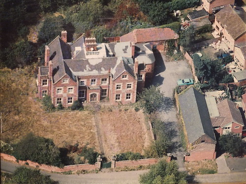
The first three pictures below were taken over a period of years by firms who overfly a likely area taking photographs 'on spec' and then send a salesman door-to-door trying to sell framed prints.
 This picture must date from the 1970s, when the path to the front gate was flanked with flower beds. The road at the front of the property, Sparrow's End Lane, was narrow and 'hugged' the outside of the front wall. This is a photograph of a print which has rather faded.
 Lack of funds in the 1980s led to ugly temporary roof repairs. The garden is unkempt, too. This is a photograph of a print.
 The aerial photography must have been taken around 2008. This is a photograph of the print the firm supplied. I complained about the poor colour balance of the print, but I've not tried to correct it. By this time, there had been significant expenditure on the main building and the small barn had been restored. Sparrow's End Lane had been re-aligned and widened to serve a new housing development, so there is now a 'wedge' of grass between the front wall and the road.
This year, I had an e-mail from Aerial Impressions, who originate in Australia. The e-mail was inviting commissions to take photographs on a forthcoming planned photographic mission in my area. I decided to place an order with them and we exchanged maps showing exactly the extent of the property to be covered. I received an acknowledgment confirming that, subject to weather, photography in my area would start within a few days.
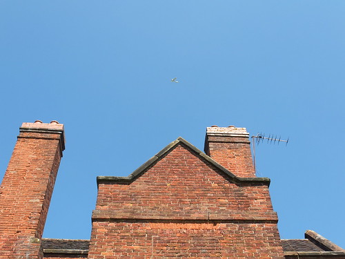
I'd almost forgotten my order when, some days later, I heard an aircraft overhead. That's not so unusual - we get quite a few light aircraft over-flying. We also get helicopters - the police and the Air Ambulance are regulars. We also get a number of military flights - Boeing 'Chinook' twin-rotor helicopters and 'Hercules' four-engine transports are commonplace. A few years ago, low-flying jet fighter aircraft were frequent fairly terrifying visitors, but that seems to have virtually ceased. The aircraft I could hear appeared to be manoeuvring so I thought "I wonder if that's the aerial survey?", grabbed my camera and went outside.
The high wing monoplane certainly appeared to be circling the property, so I attempted a picture. It always amuses me to take pictures of photographers at work, but I'd never attempted a picture of an aerial survey before. Well, the result is pretty poor - the target was too quick for me!
 My feeble attempt to capture the survey aircraft.

An enlargement of part of the above photograph
perhaps makes the aircraft more obvious.
A week or so later, I received a disc from Aerial Impressions with around 50 high-resolution shots they'd taken. I was very pleased with the result and there was confirmation that it really was the survey aircraft I'd attempted to photograph because I was clearly visible on the lawn to the left of the Hall in around half of their pictures.
 Brewood Hall in 2013. Jan is on the lawn to the left of the Hall.
There is a set of pictures Brewood from the Air which shows the village of Brewood and Brewood Hall. The Aerial Impressions pictures can be viewed in their full 21 Megapixel resolution.
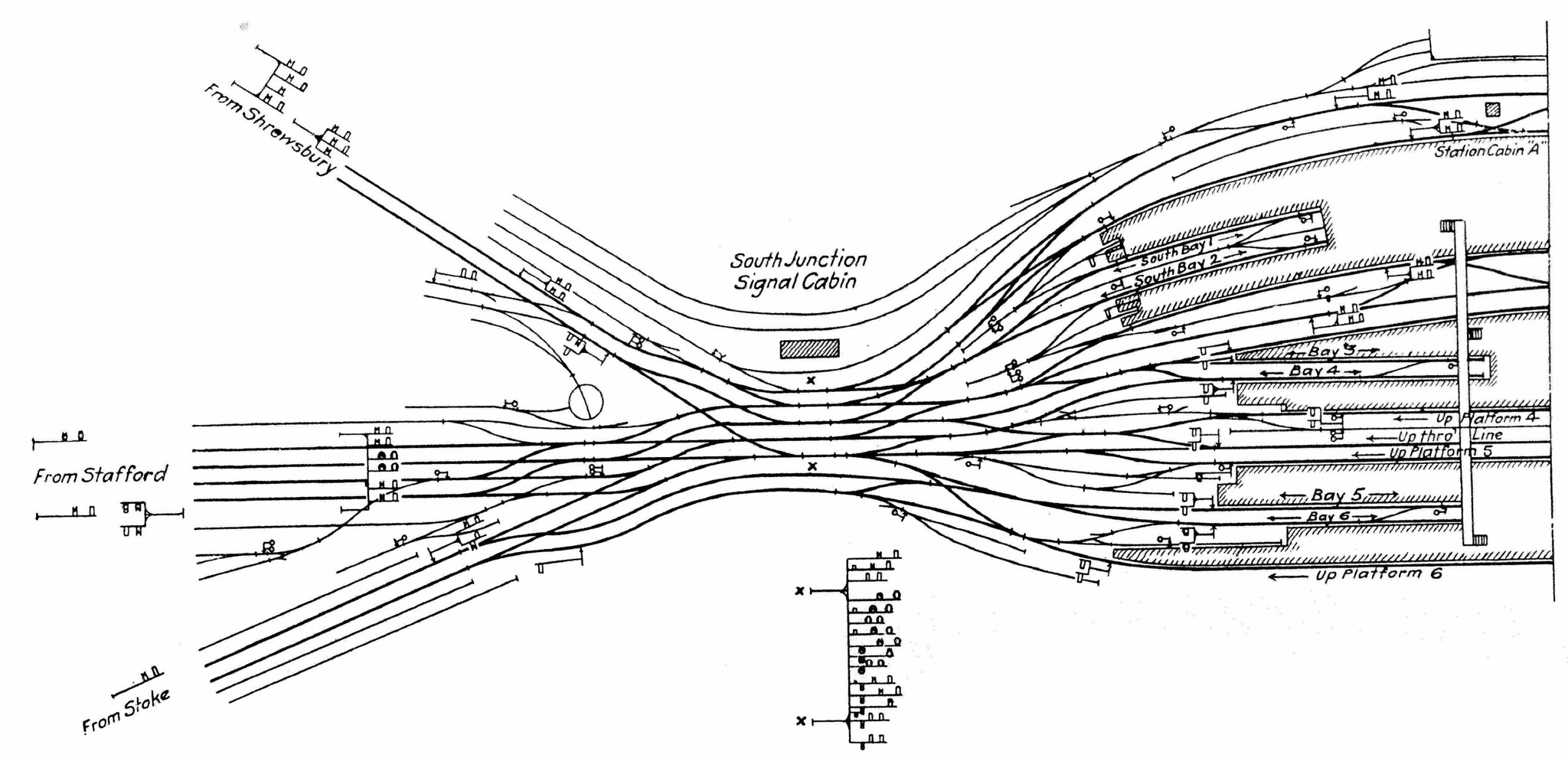
I make no apology for returning, once again, to the railways around Crewe. In the post Railways at Crewe in the '50s I talked about my early facination with the railways at Crewe, and included a sketch I made at the time showing the layout around Crewe South Junction. In the 1950s, Crewe South Junction was controlled from a large 'ARP' signal box with a Westinghouse Style 'L' Power Frame. This signal box was situated on the Up side of the lines and is briefly described here.
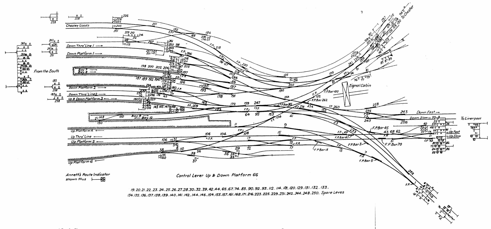
But this was not the first signal box at Crewe South Junction to use power operation of points and signals. Between 1896 and 1907, the railways around Crewe were rebuilt and expanded. F. W. Webb and A. M. Thompson developed the 'Crewe' All Electric System for use at important signal boxes. A number of signal boxes around Crewe, including Crewe South Junction, were equipped with this system which featured electric operation of points and electric operation of fairly standard looking LNWR lower-quadrant semaphore signals.
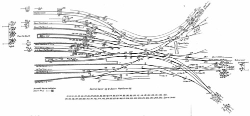
The diagram below shows the arrangements at Crewe South Junction after 1907.
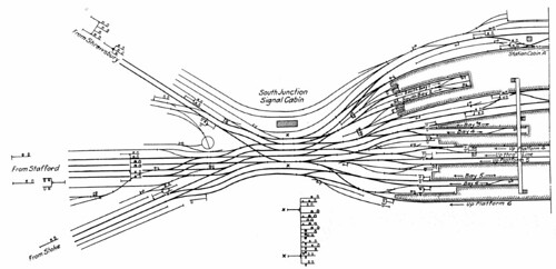 Click here for larger version
Diagram of the lines controlled by Crewe South Junction.
This diagram appeared in the book 'Power Railway Signalling' [Reference 1], together with similar diagrams for Crewe North Junction and Salop Goods Junction.
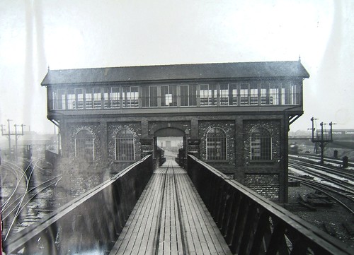
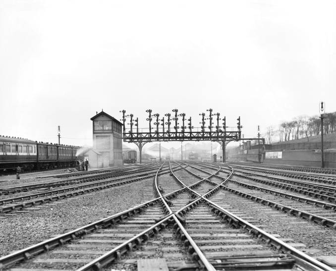
The installation included a marvellous Pratt truss signal gantry spanning the main lines just outside the signal box, shown in the picture below. I think the gantry itself survived the 1940 rebuilding - with all the semaphore signal dolls removed, the gantry was equipped with colour light signal heads and route indicators.
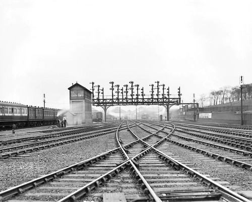 Click here for larger version
Crewe South Junction, looking north towards the station, in 1916 (Photo: National Railway Museum)
The post Crewe North Junction History outlines the succession of signal boxes at the north end of Crewe station, starting in 1863, but I don't know about early arrangements at Crewe South Junction. Can anybody help?
References
[Reference 1] 'Power Railway Signalling' by H. Raynar Wilson, published c1908, reprinted in two parts by P. Kay (ISBN 1 899890 00 9).
This report is based on information from Doctor Hla Tun, who also supplied the photographs.
The Bagan Clinic treated 5,337 patients in August 2013, bringing the total number of treatments since the Clinic opened on 6th August 2011 to 75,229.
Many patients have to set off very early in the day (or even the previous day, sleeping overnight in the Monastery compound), to register for treatment. For this reason, a free lunch is provided for patients.
 Volunteers cooking meals for waiting patients at the Bagan Medical Clinic in the Monastery compound.
In the picture below, taken in front of the Bagan Clinic, patients are queuing to be served lunch by Monks. Local donors have provided blue plastic drinking water bottles for use by the Patients - you can see these under the green awning on the right of the picture.
The majority of Patients have travelled anything from 50 to 200 km to attend the Clinic. This is why lunches are provided with the help of the Monks.
 Patients queuing to be served lunch.
Treatment Summary
The table below summarises the number of treatments per month and the total number of treatments since the clinic started.
| Month |
Patients treated |
Total treatments |
| August 2011 |
355 |
355 |
| September 2011 |
784 |
1,139 |
| October 2011 |
1,434 |
2,573 |
| November 2011 |
1,723 |
4,296 |
| December 2011 |
2,013 |
6,309 |
| January 2012 |
1,605 |
7,889 |
| February 2012 |
2,464 |
10,353 |
| March 2012 |
4,603 |
14,956 |
| April 2012 |
2,043 |
16,999 |
| May 2012 - Jan 2013 |
To be added |
To be added |
| February 2013 |
2,713 |
49,850 |
| March 2013 |
2,713 |
49,850 |
| April 2013 |
2,061 |
54,924 |
| May 2013 |
3,303 |
58,227 |
| June 2013 |
5,586 |
63,813 |
| July 2013 |
6,079 |
69,892 |
| August 2013 |
5,337 |
75,229 |
Clinic photographs in 2013
Bagan Medical Clinic (2013).
Related posts in this blog
You can find all the posts about the Bagan Medical Clinic here.

An evocative black-and-white picture of the Docks when Coal was King.
(Photo: Museum of Liverpool)
My earlier post Liverpool discussed my fascination with Liverpool. When I was young, the whole of the extensive dock system, operated by the The Mersey Docks and Harbour Board (M.D.& H.B.), was still active.
Although the docks themselves were 'enclosed', hidden behind massive walls, the Liverpool Overhead Railway gave a splendid aerial view of the activities on the many quays. See The Liverpool Overhead Railway.
The docks were served by extensive railway sidings and the M.D.& H.B. had a double-track 'main line' linking the landward side of all the docks and, for much of the route, this ran under the elevated tracks of the Liverpool Overhead Railway. Parts of this 'main line' track were 'inset' using granite setts and the cobbled route then also formed a vehicle thoroughfare.
The M.D.& H.B. ran its own fleet of steam locomotives and one of these has been preserved by Liverpool Musuem. Sadly, this locomotive is not currently on display, but is in a Museum of Liverpool store. I visited the Museum Store on 15th May 2010 (the visit is described here) and I was able to inspect the 0-6-0 saddle tank built in 1904 by Avonside. There are a few pictures of the Avonside here. A few years previously, I'd seen the locomotive when it was still on public display in the Transport Gallery at the old Liverpool Museum in William Brown Street (now called the 'World Museum Liverpool'). Prior to that (when I was quite young) I remember seeing these engines at work around the docks.
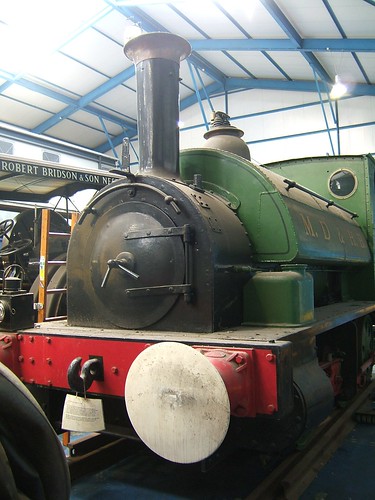
The preserved Avonside 0-6-0T is not on display,
but is in a Museum of Liverpool store.
From 1907 until 1994 the Mersey Docks and Harbour Board had their headquarters in the Port of Liverpool Building, usually called the Dock Office, an impressive building which, together with its next-door-neighbour the Cunard Building and next-door-but-one neighbour the Liver Building, form the 'Three Graces'.
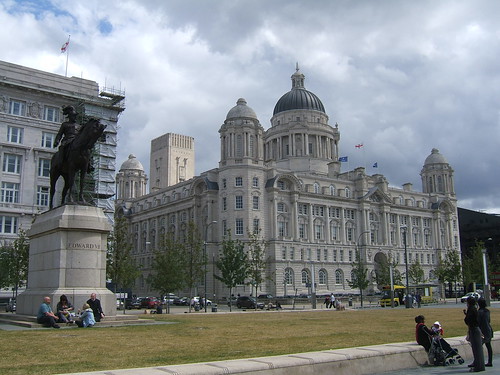 The Dock Office, Pierhead, Liverpool.
After 1994, re-development as residential and office space restored the grandeur of this Edwardian Baroque Garde II* building. For more details, see the Wikipedia article here.
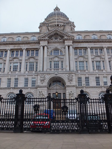
The portland stone exterior features extensive carving. The plaques on the ornamental gates feature gilded inter-twined letters 'MDHB'. Note the maritime reference on the gate pillars - gilded tridents.
There are more pictures of the Dock Office and the 'Three Graces' in my set of pictures Liverpool.
I was lucky to have seen Liverpool before major changes altered its role. Today, a reduced set of docks is operated by the Mersey Docks and Harbour Company, part of Peel Ports.
External Links
The Mersey Docks 1949.
Mersey Docks and Harbour Company (Wikipedia).
Port of Liverpool Building (Wikipedia).
Book References
[1] 'Jesse Hartley - Dock Engineer to the Port of Liverpool 1824-60' by Nancy Ritchie-Noakes, published by National Museums and Galleries on Merseyside (ISBN 0 906367 05 0).
[2] 'L.N.W.R. and the M.D.& H.B. - The History of the Dock Lines from the Records' by J. C. James, Limited Edition published c1981.
[3] 'Prince's Dock - A Magnificent Monument of Mural Art' by Adrian Jarvis published 1991 by Merseyside Port Folios (ISBN 0 9516129 0 5).
[4] 'Liverpool and its Canal' by Mike Clarke and Allison Hewitt published 1992 by Merseyside Port Folios (ISBN 0 9516129 3 X).
[5] 'An Illustrated History of Liverpool's Railways' by Paul Anderson, published Irwell Press (ISBN 1-871608-68-6).
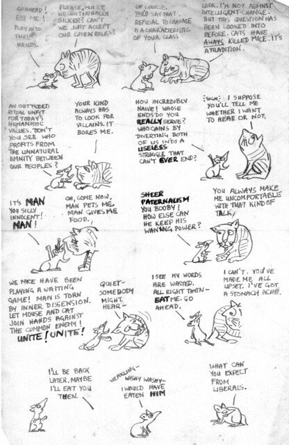
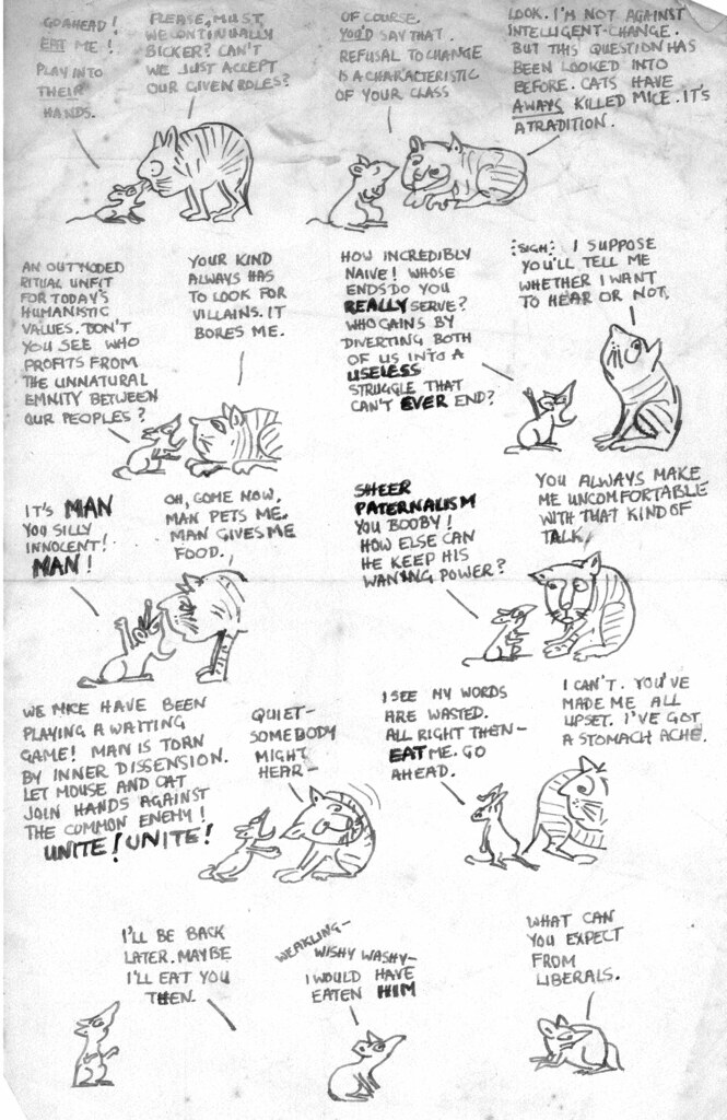
Over 50 years ago I was amused by a cartoon about a mouse and a cat. I can't remember the publication it appeared in or the cartoonist but I must have been impressed because I laboriously copied each frame by hand using a fountain pen onto a piece of foolscap paper (before 'International' paper sizes became commonplace). I found my copy (a little faded at the top), scanned it and here it is. I've called it 'Militant Mouse'.

Click here for a larger version.
With acknowledgments to the original artist.
Introduction
Railway Signalling in Britain developed over a long period and it continues to evolve. In the, as yet incomplete, series of posts 'Railway Signalling in Britain' (starting with Introduction), I described some of the equipment but I've not said much about the Signalmen themselves who made the whole system work.
The very early days of railways had something of a 'Wild West' flavour so railway companies brought ex-army men into management to impose some military discipline on the staff. But this discipline could be harsh, encouraging railwaymen, in turn, to become members of Trade Unions.
Back in the steam era, railwaymen of all grades were "a breed apart". Enginemen, in particular, had arduous working conditions but enjoyed wide respect for their skills. Signalmen were also respected for their knowledge and their ability to keep the trains moving.
In less-busy signal boxes, the work wasn't too physically tiring and there might be plenty of time for sitting around but in larger, busier signal boxes, the signalmen would be on the go throughout the shift. The majority of signal boxes were manned by one signalman at a time and locations were sometimes quite remote, so the work tended to appeal to men with independent minds who were happy with their own company (or, perhaps, were just plain 'cussed'). The safety of trains relied heavily on the integrity, concentration and training of signalmen so responsible, disciplined men were the ideal. The ideal was not always achieved and the history of signalling is a fascinating story of the piecemeal addition of ever-more-complex mechanical or electrical features to prevent signalmens' errors resulting in accidents.
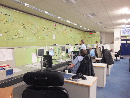
Although 'mechanical' signal boxes (that is, signal boxes which rely on physical effort by the signalman to move points and semaphore signals) still survive in the United Kingdom, their use is much reduced. Power Boxes covering larger areas are now more typical, like Manchester Piccadilly Signalling Control Centre, which I described here following a visit in March 2013.
 Manchester Piccadilly Signalling Control Centre.
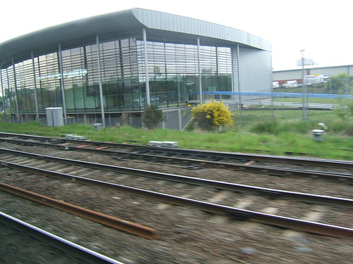
The modernising trend is continuing towards what are called Integrated Electronic Control Centres (IECC) covering even larger areas. There's a brief description in 'Wikipedia' here. The picture below (snatched from a passing train) shows the futuristic West Midlands Signalling Centre at Saltley, Birmingham, which is progressively taking over control of the the railways in the West Midlands.
 The futuristic West Midlands Signalling Centre at Saltley, Birmingham.
My Viewpoint
These notes principally relate to British Practice post-Nationalisation in the late 1950s and early 1960s. Although there was only one railway authority (British Railways Board), the system was divided into a number of 'Regions' which retained a fair amount of autonomy in some fields. In addition, those 'Regions' were the result of well over a century of amalgamations of private companies so it's perhaps unsurprising that equipment and working practices could vary significantly from place to place.
Most of the signal boxes I frequented were on the London Midland Region (and many were absorbed former London and North Western Railway establishments) so, in general, that's what I'll describe and illustrate because that's what I'm most familiar with.
In the late 1950s and 1960s I met many signalmen and, as in any walk of life, they varied a lot in knowledge and temperament. To some extent, their characters were formed by their working conditions, so I'll try to describe 'Life in the Signal Box' as I saw it.
In the post Visiting Signalboxes I talked about my interest in railway signalling and that started a whole series of posts about various mechanical signal boxes I managed to visit when I was young. There are some links in that post to articles about individual signal boxes, but I've not yet covered all the signal boxes mentioned.
 Tipton Owen Street was one of the mechanical signalboxes I visited.
Unionisation
Most railway workers joined a Trade Union and many were members of the National Union of Railwaymen, usually known as the 'NUR'. In 1990 this union merged with the National Union of Seamen to form the National Union of Rail, Maritime and Transport Workers, usually known as 'RMT' (Wikipedia article here). Most footplatemen were members of the Associated Society of Locomotive Engineers and Firemen, usually known as 'ASLEF' (Wikipedia article here).
Day-to-day conditions and promotion were regulated by agreements of Byzantine complexity made between the British Railways Board and the Unions.

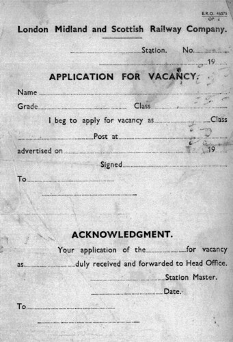
This blank L.M.S. 'Application for Vacancy' form E.R.O. 46075
was found inside a 1938 train register book.
Rules and Signalman's Regulations
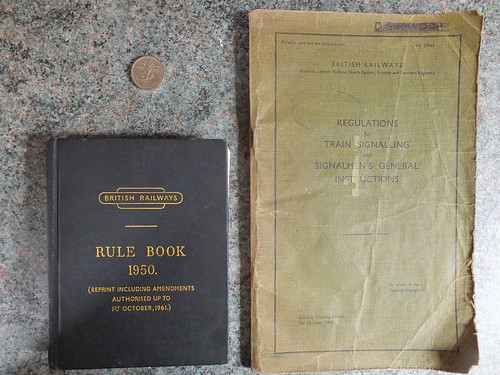
Prior to Nationalisation, each railway had its own Rule Book. By 1950, British Rail had introduced its own Rule Book, a pocket-sized book used by all the regions. The Rule Book was reprinted in 1961, incorporating all the amendments to date.
Signalmen additionally worked to the "Green Book" or, to give its proper title 'Regulations for Train Signalling and Signalmen's General Instructions' issued in two versions in 1960. Whilst the Eastern, London Midland, North Eastern, Scottish and Southern regions managed to share one version, the Western region (never really regarded as a 'team player') needed a version of its own.
 The 1961 Reprint of the 1950 British Railways Rule Book alongside the Signalmen's "Green Book" - 'Regulations for Train Signalling and Signalmen's General Instructions' (pound coin included to show size).
This was not all of the paperwork signalmen needed to be familiar with - there were also Sectional Appendices (more on Sectional Appendices can be found on Brian Robertson's site here), Local Instructions, Working Timetables and Weekly Notices (which included details of Engineering Work and Special Trains).
Classification of Signal boxes
Signalboxes were graded according to how much work was done, largely based on the number of lever movements, from Class 4 (relatively quiet) to Class 1 (busy) and Special Class (demanding). A single signalman could cope at most signal boxes but some large or busy boxes required more than one. Some boxes had a junior position which might be termed 'Telephone Boy' or 'Booking Lad' to share the work with the signalman. Strategically-important boxes sometimes had a senior position of Regulator, who would decide on the order of trains.
Hours of Opening of Signalboxes
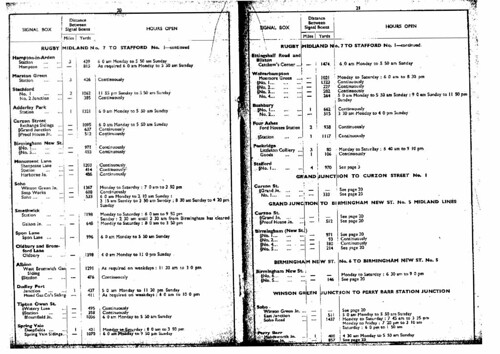
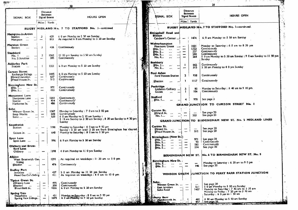
Some signalboxes had to be open continuously if any trains were to run, such as Tipton, which controlled a busy level crossing. Other signalboxes might not be needed at night, or for parts of the weekend, such as Deepfields. There were also signalboxes that only needed to be open intermittently 'as required', such as Tipton Curve Junction. A publication showed the normal hours of opening of each signal box, but this could be changed to cater for special trains, engineering works or accidents.
 Click here for larger image
Double-page from 'Hours of Opening of Signal Boxes' Book, showing the Stour Valley line.
Shift Working Patterns
This depended upon the specified opening hours but there were normally three 8-hour shifts: 6.00 a.m. to 2.00 p.m. (called 'Early Shift'), 2.00 p.m. to 10.00 p.m. ('Late Shift') and 10.00 p.m. to 6.00 a.m. ('Night Shift'). Each week, these shifts would rotate so that the man on 'Earlies' in one period would be 'Nights' in the next period. Similarly, the 'Night' man would move to 'Lates' and the 'Late' man to 'Earlies'. Since Rest Days had to be given, three men could not keep a box open continuously and a fourth man was needed to cover Rest Days. Originally, there would be three 'Regular' men who would always work the same box and their 'Rest Days' would be covered by a 'Relief' signalman who would be trained to operate a number of signal boxes, providing Rest Day 'cover' at each of them. 'Relief' signalmen would also deputise for 'Regular' signalman who were on Annual Leave or Sick. Arrangements could become quite involved.
When I was visiting signalboxes around the West Midlands in the late '50s and early '60s, the number of 'Regular' men seemed to be reducing. Modernisation of the railways was well in hand and it was clear that re-signalling schemes were going to need much smaller numbers of staff in the future. The proportion of turns covered by 'Regular' men was reducing and, particularly as older signalmen retired, 'Relief' signalmen were kept busy making up the shortfall. Signalmen were allowed to work up to 12-hour shifts and some men (particularly those with young families) were happy to accept overtime. But, of course, the writing was on the wall and the period leading up to the commissioning of Wolverhampton Power Signal Box on Monday 16th August 1965 was a sad time as many of my friends received redundancy notices.
The Block System
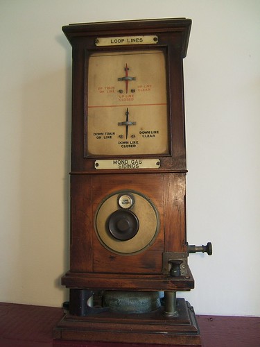
Most double-lines were controlled by the Absolute Block system, where signalmen communicated with adjacent signal boxes using block signalling equipment comprising electric single-stroke bells and galvanometers. There's a brief description of Block Instruments here.

L&NWR-pattern 'DN' Permissive Block Instrument, originally in use at Watery Lane Signalbox.
The single-stroke bell was controlled by a tapper key, a bit like a Morse Key. This key protruded from the block instrument case. Most of the key was metal but there was a dished knob made of a material like Ebonite which could be pressed down by a forefinger to sound the bell in the adjacent box. A spring would push the key back up, ready for the next stroke. This is a bit different from a Morse Key where there would normally be a round knob you could grasp with a thumb and two fingers. The Ebonite knobs were often noticeably worn away, having been used for the passage of many thousands of trains. Also the spring return could become rather weak, so some signalmen would use their thumb to help push the key back up. It was a good idea to avoid touching the metal part of the key - when the electric current was disconnected at the end of a stroke, the coil in the bell at the adjacent box would generate a brief 'back e.m.f.' voltage which could be many hundreds of volts and give a nasty shock. If the signalman happened to be holding a lever with the other hand, providing a more efficient 'earth', the shock was more severe.
Signalling a through train involved accepting the 'Is Line Clear?' from the box in the rear ("Taking On"), obtaining 'Line Clear' from the box in advance ("Sending On"), clearing the signals ("Pulling Off"), observing the train as it passed, sending 'Train Entering Section' ("Section") to the box in advance, ensuring a tail lamp was carried, replacing the signals, giving 'Train Out of Section' ("Knocking Out") to the signal box in rear and waiting for the box in advance to send 'Train Out of Section'. Even this repetitive process could get quite demanding at busy times when trains followed one another on short headways and, of course, trains were being handled in both directions.
The Train Register Book
A key feature of signal boxes was the Train Register Book, which I've described here. Every bell signal was recorded with its time, together with explanatory notes. Entries were supposed to be made as things happened, so as to act as an aide-memoire to a temporarily-confused signalman. Some signalmen might let a number of trains pass, remembering only, say, passing time, before bringing the train register up to date and reconstructing all the individual timings based on their familiarity with the location. The Train Register was the equivalent of the 'Black Box Recorder' for the mechanical age. In the event of an incident, the Train Registers from all the signal boxes involved would be collected (each signal box would start a new Train Register so that they could continue to log movements). The collected registers would then be subjected to forensic study to try to establish whether any irregularity has been involved. Of course, all bell signals were logged in the registers of two adjacent signal boxes so the time Box A claims he 'Sent On' a train to Box B should be the same as the time Box B enters for 'Taking On' the train.
The Box Clock
For the Train Register system to work, boxes had to have an accurate reference to the time. Every signal box had a wall clock, often mounted above the desk holding the Train Register Book. These clocks were spring-driven and required winding on a regular basis. To ensure that clocks did not become inaccurate, a Time Signal was transmitted once daily. Where signal boxes had at least one telephones, the time signal could be issued by telephone, but, where necessary, the time signal could be relayed using the block bell from an adjacent signal box with a telephone. In the West Midlands, all the boxes I visited had at least one omnibus telephone (see 'Communications' below) connecting all the signal boxes on a stretch of line together and usually extended to the District Control Office in Birmingham. The Control Office would have had an accurate clock system and at 9.00 a.m. each day it would issue the Time Signal to all signal boxes by a series of short rings on the Control Telephone circuit, so that each signal box received a distinctive 'Buzz-Buzz-Buzz-Buzz-Buzz ...'. On receipt of the Time Signal, signalmen corrected their clock as necessary and recorded in the Train Register book the necessary correction. Anything more than two or three minutes correction would initiate remedial action. Sometimes, there would be no Time Signal at 9.00 a.m. In this case, it would often be sent at 10.00 a.m. I never found out quite why this occurred.
The Lever Frame
The role of the signalman was an interesting blend of the celebral and the physical. Working the lever frame was definitely physical but it was not a matter of brute force but rather of learning the correct technique for each lever to achieve success. Some levers, particularly for points and signals nearer the box, often needed only moderate effort. Levers which operated more than one set of points or signals at a greater distance could be harder. It was sometimes better to use body weight to get a 'swing' to move a set of point blades correctly, as otherwise the point blades might not move sufficiently. But too much 'swing' could cause the blades to 'bounce' and still not 'fit-up'. Failure could result in not being able to bolt the points with the associated Facing Point Lock lever (in the case of facing points) or clear the signal for the move (because the Signal Detector was 'tied'). Distant signals, often out of sight on the end of three quarters of a mile of signal wire, could be very problematic, particularly if the cable run had become fouled by weeds or temperature change had slackened the wire. Various forms of Slack Adjuster were often provided but correct adjustment could be tricky. Where distant signals were out of sight, electrical repeaters were provided with three indications - 'ON', 'OFF' and (where the signal arm stood between valid 'ON' and 'OFF' positions) 'WRONG'. It could be very dispiriting to have used what you were confident was the correct technique only to have the repeater stubbornly show 'WRONG'.
In some signalboxes, it was considered sacrilege to operate a lever with your bare hands, and the use of a duster was mandatory. It's certainly true that perspiration from the hands can tarnish metal levers but most of the boxes I visited, even those that were kept very clean, seemed to have a more robust view.
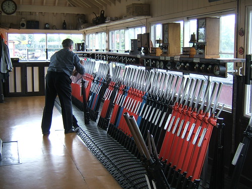
 Part of a large mechanical lever frame. This is the preserved Exeter West signalbox, preserved at Crewe Heritage Centre.
Communication Facilities
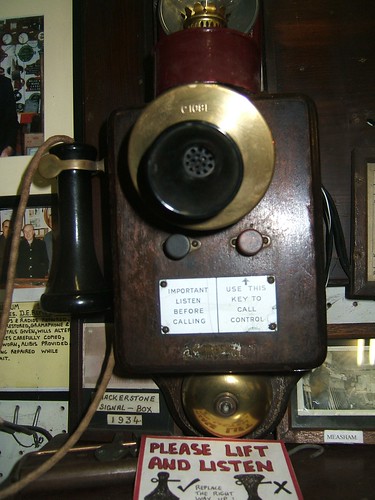
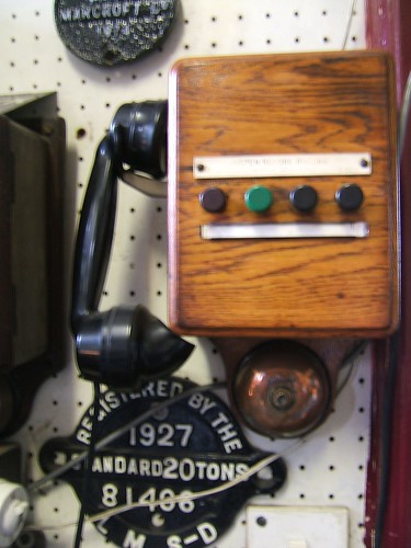
In the early days, the block signaling equipment might be the only communication with the outside world. There were bell codes to cope with various mishaps such as 'Train passed without tail lamp', 'Train running away wrong line' but there were limits and over a period telephones were introduced in most signal boxes. The pictures below show a couple of patterns of telephones widely used in signal boxes. At larger boxes, a Key and Lamp Unit might be installed, so that a number of circuits could be answered using just one handset. A Key and Lamp Unit is described here.
Some signalmen, if not otherwise engaged, would talk incessantly about every topic under the sun on the 'Box-to-Box' omnibus telephone circuit to whoever would listen, some liked to "ear-wig", listening to the wide-ranging discussions but rarely making a contribution and some used the telephones only for operational reasons.
I hope to write more about railway communications in the future.

Wall-mounting Local Battery 2-button D.C.-ringing Omnibus Telephone with separate Microphone and Receiver displayed in Shackerstone Railway Museum.

Wall-mounting Local Battery 4-button D.C.-ringing Omnibus Telephone with combined Microphone and Receiver (Hand Micro-Telephone) displayed in Shackerstone Railway Museum.
Heating Signalboxes
Signal boxes could be cold, draughty places. The ground floor of a signal box, the 'Locking Room', was provided with a long slot at ground level to allow the signal wires and point rodding to be led outside. This admitted quite a gale, which could readily find an exit onto the operating floor 'upstairs' through the numerous slots which allowed the levers in the frame to be moved. It was not uncommon to find pieces of old carpet laid across the lever slots on the operating floor, leaving only the regularly-used levers exposed. In addition, there were usually lots of glazed window units on the operating floor, many of which could be slid open, giving rise to draughts even when closed. Finally, signal boxes were located based on operational requirements and the need to give the signalman a good view of the railway he was controlling. This often meant that signal boxes were in rather bleak locations.
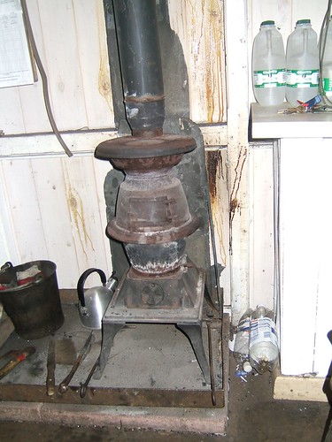
Heating to counter the cold was usually by means of a cast-iron solid fuel stove. A signalman re-opening a signal box after a period of closure could find it cold and damp, so getting a good fire going was normally a priority. Once lit, it would normally be kept lit until the next period of closure. Often, the stove was the only method of boiling water or cooking. The picture below shows the stove at the preserved signal box at Shackerstone.

The Signalbox Stove.
Illumination of Signalboxes
A lot of the signal boxes I visited were gas lit, although some had mains electric light. At least one (Tipton Curve Junction) was lit by 'Tilley' pressurised paraffin lamps. I was delighted to find that 'Tilley' lamps are still available - the website is here.
Toilet Facilities
Not many signal boxes had facilities connected to a main sewer. The most common arrangement was an 'Elsan' chemical toilet, often housed in a small wooden 'shed' on the operating floor level, usually reached from the landing at the top of the (external) signal box steps. The arrangement at Bloomfield Junction - a sliding door on the back wall of the signal box gave access to a separate, small landing with metal handrails leading to the usual wooden 'shed'. A modernised arrangement provided a pre-cast concrete 'hut' adjacent to the signal box. 'Elsan' are still in business but the current arrangements shown on their website seem a vast improvement on what I remember.
Furnishings
Furnishings were usually fairly basic. Generally, the floor of the box would be covered by a heavy-duty brown linoleum but this was not universal.
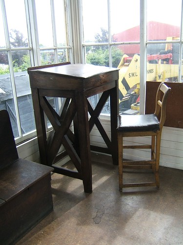
There was always a tall writing Desk, with the Train Register book open on the sloping top. The sloping top was hinged to reach the storage space inside which held various documents such as a copy of the Working Timetable and Weekly Notices and supplies of Single Line Working forms. It was possible to find quite old documents abandoned in this storage space. The photograph below shows a rather nice 'high chair' but I think this refinement was missing at the signal boxes I visited - normally, signalmen would stand at the desk to enter times in the register.

The Desk in the preserved Crewe Station 'A' Box.
There would usually be some sort of 'easy chair' pulled up near the stove where signalmen would spend free time. This would be arranged so that the signalman could relax in the chair and talk on the box-to-box omnibus telephone circuit. Some of these chairs were life-expired and had had various repairs carried out. I particularly remember the throne-like chair at Bloomfield Junction. The 'wings' and back had been massively extended, using odd bits of orange box wood, presumably to shield the signalman from the draughts but creating the appearance of a rather beat-up sedan chair.
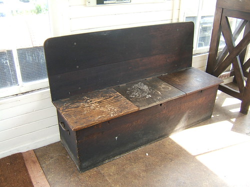
There would also be a Locker for Signalmen's personal possessions. The example shown in the photograph below is a common design, divided into three lockable sections so that up to three regular signalmen could each have private storage space.
 The Locker in the preserved Crewe Station 'A' Box.
Reporting Responsibilities
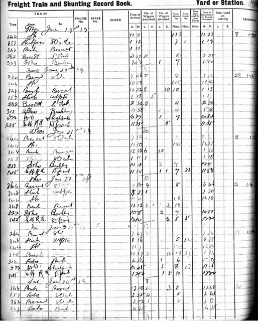
Boxes with more freight involvement often completed a 'Freight Train and Shunting Record Book' detailing freight trains, time spent, vehicles attached and detached. Abstracts from this would be passed to the Control Office by telephone regularly.
 Page from a Freight Train and Shunting Record Book (dated 1939).
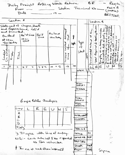
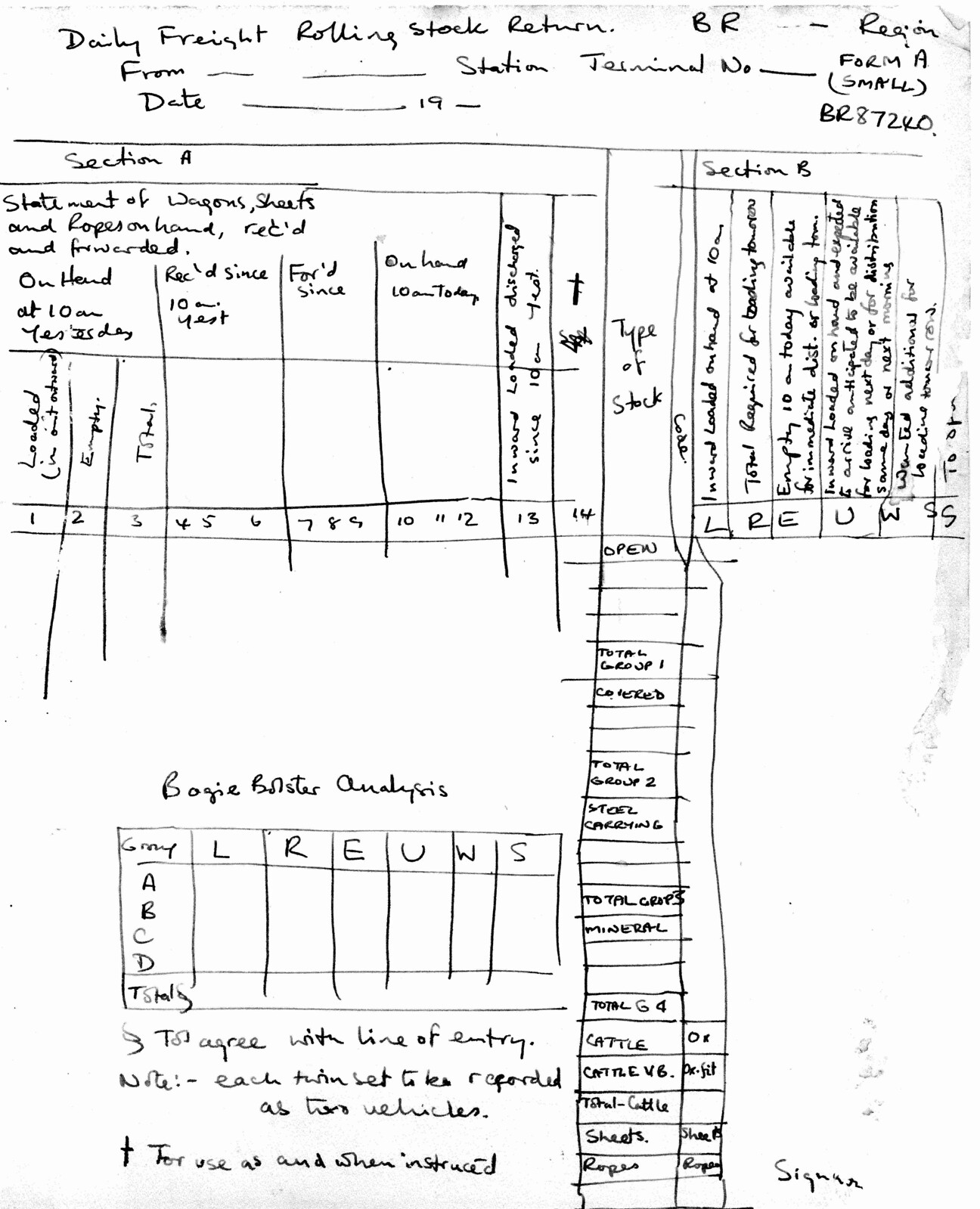
Some locations had to submit a 'Daily Freight Rolling Stock Return' to assist the Control Office with keeping track of freight vehicles (some hope - see my short post here) and ensuring that yards had sufficient empty wagons on hand for traffic to be loaded. I didn't get a copy of this comprehensive return but I did do a quick sketch.

Click here for larger image
Daily Freight Rolling Stock Return FORM A (SMALL) BR87240: Sketch showing layout of this form.
These old document systems were eventually overthrown. In the late 1960s, British Rail invested heavily in computers and a system called 'TOPS' (Total Operations Processing System) which had worked well on the Southern Pacific Railroad in America was introduced. There's a 'Wikipedia' article on TOPS here. By the 1970s 'TOPS' was also controlling freight wagons, as described here.
Supervision of Signalmen
Each Stationmaster or Yardmaster would be responsible for one or more signalboxes in his area, making regular visits to each signal box. All official visitors to a signal box, such as the Stationmaster, would make an entry in the Train Register. The Stationmaster would also make a check of entries in the train register and entries of interest (like "Clock Correct at 9.00 a.m. Time Signal") would receive a 'Tick'.
The 'Green Book' specified the exact sequence of Bell Codes to be used and complying with this was called "Working 'Up'". However, it was common for signalmen to use a somewhat simplified version called "Working 'Loose'". For instance, receipt of 'Two Beats' (Train Entering Section) was supposed to be acknowledged on the bell and the Block Indicator turned to 'Train on Line'. When "Working 'Loose'" the bell acknowledgement would be omitted.
Provided a signalman spotted the approach of the Stationmaster whilst working 'Loose', the adjacent signal boxes would be warned to start working 'Up' by sending the unoffical bell signal '1-2-1, 1-2-1' ("Gaffer Approaching"). The genuine bell signal '1-2-1' was used (where authorised) for 'Train Approaching'.
The Signalmen's Inspector could also appear unexpectedly. He was responsible for 'passing-out' new signalmen and would periodically make visits to signal boxes. He could be relied upon to have a detailed knowledge of all the signalling regulations, so signalmen could not hope to bluff this gentleman.
Book References
There are a number of books written by men who were signalmen. I've listed a couple by Adrian Vaughan:-
[1] 'Signalman's Morning' by Adrian Vaughan, published John Murray (ISBN 0-7195-3827-0).
[2] 'Signalman's Nightmare' by Adrian Vaughan, published John Murray (ISBN 0-7195-4285-5).
I'd visited a number of signal boxes before being introduced to Catchem's Corner in the late 1950s. But "Catchem's" (as it was always called) was the first signal box I learnt to operate. It fired my imagination and led to a period where I spent long periods in various signal boxes around the West Midlands. My blog post Visiting Signalboxes describes these early visits.
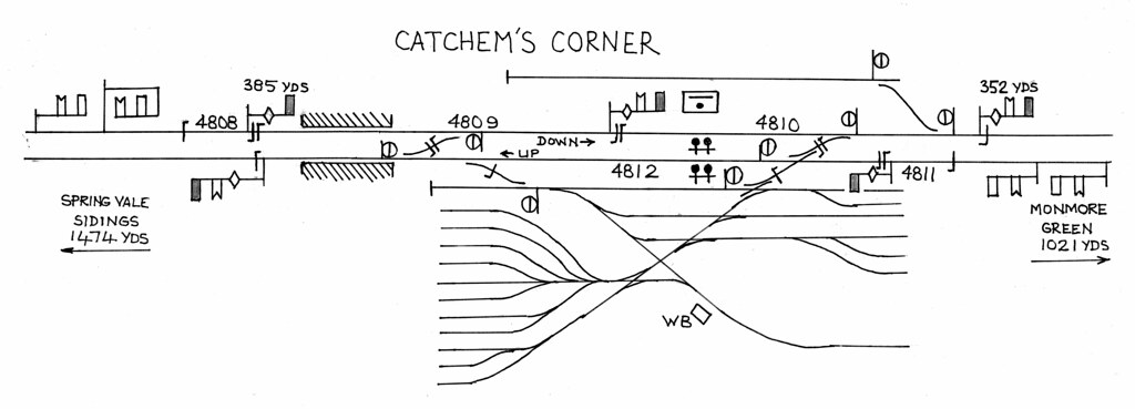
Catchem's Corner Signal Box lay on the Stour Valley Main Line from Wolverhampton High Level to Birmingham New Street. The adjacent signal boxes were Monmore Green (1021 yards in the Wolverhampton direction) and Spring Vale Sidings (1474 yards in the Birmingham direction).
The double-track line was more-or-less straight on a rising gradient through Monmore Geen and past Catchem's Corner on an embankment, curving left through Ettingshall Road and Bilston Station and on to Spring Vale Sidings. The signal box controlled the access to Ettingshall Road Goods Depot which was at a lower level than the main lines, necessitating a fierce gradient on the access sidings. At the time of my visits, this was quite a busy depot as the immediate area was home to a number of large engineering works, notably John Thompson.
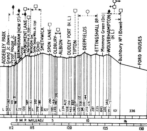
 Gradient Diagram of Stour Valley Line.
The signal box, situated on a broad embankment on the down side of the main lines, was a standard L.M.S. pattern with a brick base, wooden top, gable roof and with the lever frame on the side of the box away from the track.
The L.M.S. lever frame placed all the interlocking on the operating floor in a compact form, behind the levers. The catch-handles on the levers were the 'trigger' pattern fitted behind the lever (like an old-fashioned car handbrake). To reduce the walking the signalman had to do, L.M.S. practice placed all the main running signals near the centre of the frame. Bracketed from the roof on a series of bars the block shelf ran the length of the lever frame and accommodating various electrical repeaters, two L&NWR Block Signalling Instruments and a Block Switch. The Signal Box Diagram was suspended above the block shelf, showing the layout of points and signals controlled by the signal box together with the distance to principal features from the box and a gradient diagram. Heating was provided by a coal stove situated in the middle of the glazed wall nearest the track. The floor was covered with heavy-duty brown linoleum.
 Click here for larger image.
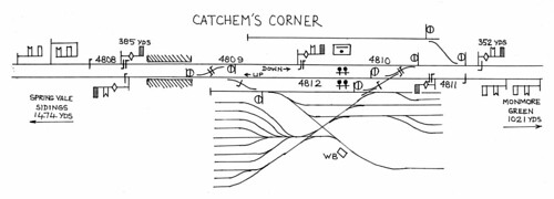
Sketch plan of area controlled by Catchem's Corner Signal Box.
I didn't have a camera of my own at that time so I have no pictures of the box. If I produced any sketches at the time showing the track layout, they don't appear to have survived (it was around fifty years ago), so the simplified sketch above is made from memory, combined with information from the John Swift diagrams (see 'References' below).
Ettingshall Road Goods Depot and Sidings
There were no facing points on the main lines so access to all sidings was by drawing ahead and setting back. The main sidings, crane roads and goods sheds were reached by setting back from the Down Main but there was another group of sidings which could be used by Up trains attaching or detaching.
On the Down side, there was a single, long siding reached by drawing ahead and setting back. I think that this was probably a addition during World War II, to act as a refuge for a Down freight train which Wolverhampton was not ready to handle, allowing the main line to be cleared for more important trains.
Ettingshall Road and Bilston Station
This was a modest affair served by stopping trains. It had two wooden platforms flanking the main lines and the main station buildings on the Up side were also wooden. Access to each platform was by long ramps from Parkfield Road, which crossed under the railway a few yards on the Birmingham side of the station. As far as I remember, there was an electric bell operated from the signal box to alert the station staff to an approaching stopping service.
Down Signals
Down Outer Distant was mounted underneath Spring Vale's Down Home on a short LMS tubular post outside Spring Vale box.
Down Inner Distant was mounted underneath Spring Vale's Down Starter - a distinctive 'Gallows' signal with the arms on a wooden cantilever to the right of a lattice main post [see Note 1].
Down Home 1 was an LMS tubular post.
Down Home 2 was a very short LMS tubular post, just outside the box, with Monmore Green's Down Outer Distant carried underneath.
Down Starter was an LMS tubular post, with Monmore Green's Down Inner Distant carried underneath.
Up Signals
Up Outer Distant was mounted underneath Monmore Green's Up Home on a LMS tubular post.
Up Inner Distant was mounted underneath Monmore Green's Up Starter on a LMS tubular post.
Up Home was an LMS tubular post [see Note 2].
Up Starter was Upper Quadrant on a tall wooden post - the post almost certainly a survivor from the previous L&NWR lower quadrant arrangement. A Distant for Spring Vale was carried underneath.
Detonator Placers
Emergency Detonator Placers on the Up and Down main lines were operated from two levers in the centre of the lever frame.
Block Instruments, Block Control, Track Circuit and Signal Repeaters
Two L&NWR Block Signalling Instruments and a Block Switch stood on the Block Shelf. The block instrument connected to Spring Vale Sidings had a larger bell dome, giving a lower tone, allowing the signalman to distinguish that block bell from the one to Monmore Green, which had a smaller bell dome and a higher tone. The Block Switch allowed Catchem's Corner to "switch out", so that the block section extended between the signal boxes on either side which remained "switched in". Much later, I remember working Tipton Station box when the next box was Wolverhampton No. 1 (because Bloomfield Jn., Deepfields, Spring Vale, Catchem's and Monmore Green were closed).
Three track circuits covered the two main lines within 'Station Limits' and, outside the first 'Stop' signal in each direction, there was a 'Berth' track circuit (probably 200 yards in length). If 'Line Clear' had not been obtained from the next signal box, the 'Berth' track circuit held the home signal electrically locked until an approaching train had been 'brought under control'. The state of each track circuit (Clear/Occupied) was shown by electromechanical indicators fixed to the front of the block shelf. There were certainly repeaters for the weight bars of the distant signals (slotted with the arm above - see the article Slotting). I can't remember whether any of the stop signals had arm repeaters, or which signals had lamp repeaters. There's a general description of signal repeaters in the article Signal Arm, Slot and Lamp Repeaters.
Hours of Opening
In common with a number of signal boxes on the Stour Valley at the time, Catchem's Corner was normally open from 6.00 a.m. Monday to 5.50 a.m. Sunday.
Historic Events
The splendid 'Railways Archive' site has a PDF of the report following an accident at Catchem's Corner in 1912 here. It gives a fascinating insight into how the railway was then, plus clearly showing how a moment's lapse of concentration can have disastrous consequences.
In 1965, after I'd stopped visiting Catchem's Corner, John Thompson shipped a series of loads called the "Heaviest Single Load carried by British Railways" through the Ettingshall Road Goods Yard. There's a detailed article with photographs about these loads in 'BRILL' (see 'references ' below). I did signal one of these loads through Tipton Curve Junction and I've described that here.
Notes
[Note 1] Near the end of mechanical signalling on this line, this signal was replaced by a conventional tubular post, with a 'Shunt Ahead' arm underneath. This later arrangement is shown in the post Railway Signalling: Spring Vale Sidings Box.
[Note 2] Near the end of mechanical signalling on this line, a motor-operated distant for Spring Vale Sidings was placed underneath the Up Home. This later arrangement is shown in the post Railway Signalling: Spring Vale Sidings Box.
References
For a track diagram produced by John Swift showing Catchem's Corner, refer to the Signalling Record Society publication 'British Railways Layout Plans of the 1950's', 'Volume 11: LNWR Lines in the West Midlands' (ISBN: 1 873228 13 9).
There's nothing left now except plain double track - see 'Railway Track Diagrams Book 4: Midlands & North West', published by Trackmaps (ISBN: 0-9549866-0-1).
'Keep Big Loads off the Roads - a record of the single heaviest load carried by BR' in 'British Railways Illustrated' ('BRILL') Volume 9 Number 3, December 1999.
The following brief report is based on information from Doctor Hla Tun, who also supplied the photographs.
Second Bhamo Cruise 2013
On 31st August 2013, the 'Road to Mandalay', on its second Bhamo Cruise in 2013, anchored off Shwe Paw Island, at the end of the Ayeyarwady River's Second Defile. The Guests were able to visit the island and participate in the distribution of stationery to the 103 students at the island's school.
 Students at Shwe Paw Island school standing on benches, ready to recite poems to the visitors after the distribution of stationery.
There is no clinic, no doctor and no nurse on Shwe Paw island. Patients need to go to Shwe Ku Town on the 'mainland' if they wish to see a doctor. Doctor Hla Tun always treats patients during his visits to the island and the shelter at the ferry landing stage is used as a makeshift 'clinic'.
 Treatment of patients in the shelter at the ferry landing stage.
Third Bhamo Cruise 2013
On 15th September 2013, a further visit was made to the island school and, once again, stationery was distributed.
On the same day, Doctor Hla Tun treated patients in the shelter at the ferry landing stage.
The photographs above are from the set RTM Social Contribution.
I've previously visited Shwe Paw Island myself in 2010 and 2012. My reports are here (for 2010) and here (for 2012).
[Visit during Third Bhamo trip added 25-Sep-2013]
The following brief report is based on information from Doctor Hla Tun, who also supplied the photograph.
During the 'Road to Mandalay' second Bhamo Cruise in 2013, a donation of 80 sets of Blood Bottles and Blood Sets was made to Katha District Hospital. These are used for collecting blood from blood donors at the hospital. The blood is used for transfusions during emergency surgical operations or emergency situations involving profuse bleeding.
This was the second occasion on which donations of Blood Bottles and Blood Sets have been made to the hospital.
 Donation of empty Blood Bottles and Blood Sets to a Laboratory Technician at Katha District Hospital.
The photograph above is from the set RTM Social Contribution.
On 14th September, during the third Bhamo Cruise in 2013, a further donation of 48 sets of Blood Bottles and Blood Sets was made to the hospital. That was third donation of Blood Bottles and Blood Sets to the Hospital, bringing the total number of Blood Bottles donated to 128.
I've not visited the Katha District Hospital but I've been to Katha in 2010 and 2012. My reports are here (for 2010) and here (for 2012).
[Details of donation made on 14-Sep-2013 added on 29-Oct-2013]
When the Vintage Tea Party (described in a post here) was being planned earlier this year, an interest in letting people see some of the inside of Brewood Hall was discussed. There have been a number of visits in the past (including two organised by Brewood Civic Society). It was agreed that the Vintage Tea Party organisers would take bookings for conducted tours on the 14th and 15th September 2013.
About 120 people booked so they were arranged into four groups - 2.00 p.m. and 3.30 p.m. on Saturday 14th and at the same times on the Sunday.
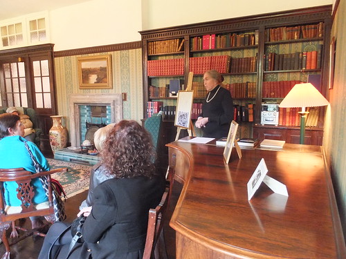
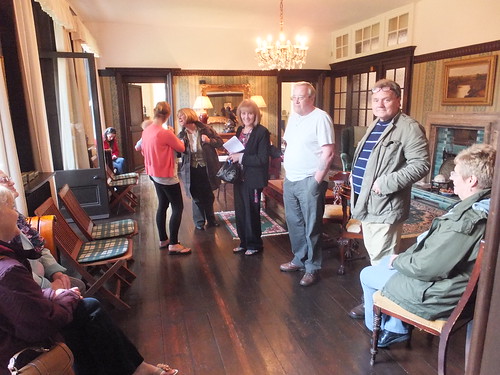
Each group assembled in the Lounge Hall at the appointed time where there was sufficient seating for (most) people. Jan gave a talk lasting around half an hour about the history and architecture of Brewood Hall (the post Brewood Hall has some information about history and architecture).
 Jan talks about the history and architecture of the Hall.
 Marion and Visitors in the Lounge Hall.
The group was then divided into two. Jan led the first party on a tour of the principal rooms of the building, finishing in the oak-panelled Dining Room. At the same time, Marion Reeves led the second party on a tour of the Small Barn (which received a major restoration a few years ago - the post Brewood Hall Small Barn has a little more information) and the Gardens (when the weather permitted), finishing back in the Hall itself. Jan then took the second party around the principal rooms and Marion took the first party to see the Barn and Gardens.
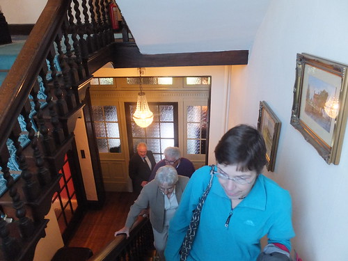
 Visitors climbing the Main Stairs to the First Floor.

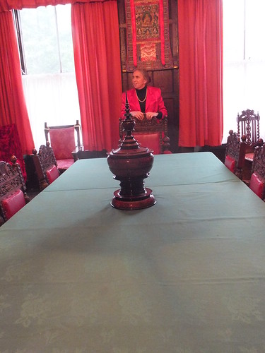
Jan describes the Tibetan wall-hanging - 'Thangka' - on the panelling behind her in the Dining Room.
At the beginning of September, the weather had turned much colder. On the Saturday, the weather was bright, cold but mainly dry. The Sunday was dull, cold and with intermittent rain. If visitors found the weather too inclement for a tour of the Gardens, they were invited to spend additional time in the Oriental Room, which has numerous artefacts from various countries.
Everybody seemed to enjoy the event and a number of the Visitors commented that they found the tour very interesting.
No admission charge was made for these tours, but donations were invited towards the work of the Jan Ford Foundation which supports charitable initiatives in Myanmar (Burma) including a Free Medical Centre, various School Projects and a number of Orphanages. There are a number of posts describing these initiatives which can be found here.
There are a few pictures taken during these Conducted Tours in the set Tour of Brewood Hall, September 2013.
There are a number of posts which describe earlier visits to Brewood Hall:-
NADFAS visit to Brewood Hall
Visit to Brewood by 'History Walks'
Wulfrun College Retired Staff Association visit Brewood Hall
'Inner Wheel' visit to Brewood Hall
Brewood Scouts visit Brewood Hall
Staffordshire Libraries visit to Brewood Hall
Brewood Civic Society visit to Brewood Hall
You can find all the posts about Brewood Hall here.

 Locomotive No. 6 'Fox' in service (Photo: 'The Pictorial Encyclopedia of Railways' by Hamilton Ellis, published by Paul Hamlyn, 1968).
 'Cecil Raikes' in colliery service at Shipley.
 'Cecil Raikes' at the Southport Steam Centre (Photo: Southport Steam Centre).