Wednesday, 15 May 2013

Victoria Station, London

Brought up in the Midlands in the early days of the post-war Nationalised railway, the former Southern Railway was very much a 'foreign railway' to me. It was some time before I started to discover some of the history of the lines in the south of the country.

Then and Now

The 'Golden Arrow' leaves Victoria at 10.00 a.m. in steam days headed by a Bulleid 'Pacific' (Photo: British Railways).

Approaching Victoria in 2011 on the Brighton Lines, looking towards station.

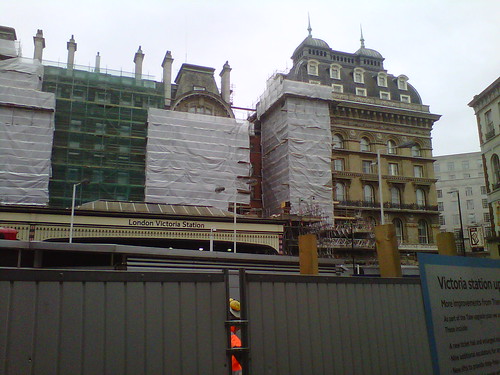
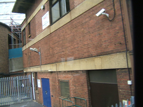
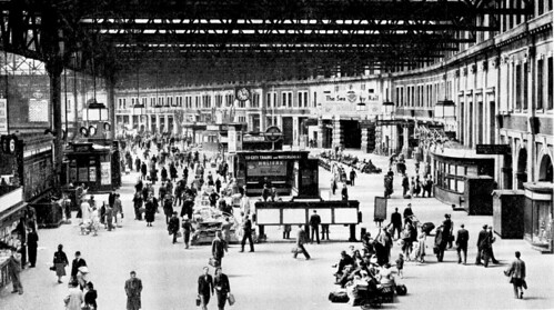
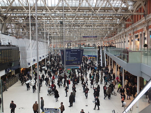
The tower of the building designed by Albert Lakeman in 1939 for Imperial Airways is visible in both pictures. After the Second World War, Imperial Airways was nationalised and became part of British Overseas Airways Corporation. The building is now occupied by the National Audit Office.

Click for larger image
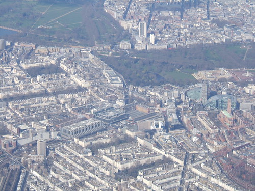
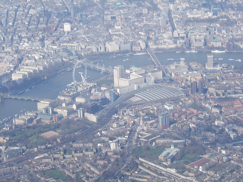
Victoria Station in a 2009 aerial view. The terminus is in the middle of the picture, with the approach tracks towards the lower left. The 'country end' of the station is virtually buried under modern developments. Hyde Park is top left, with Green Park and Buckingham Palace to the right. Centre right is Westminster Cathedral (Roman Catholic), designed in the late 19th century by John Francis Bentley in Early Christian Byzantine style.

Brief History

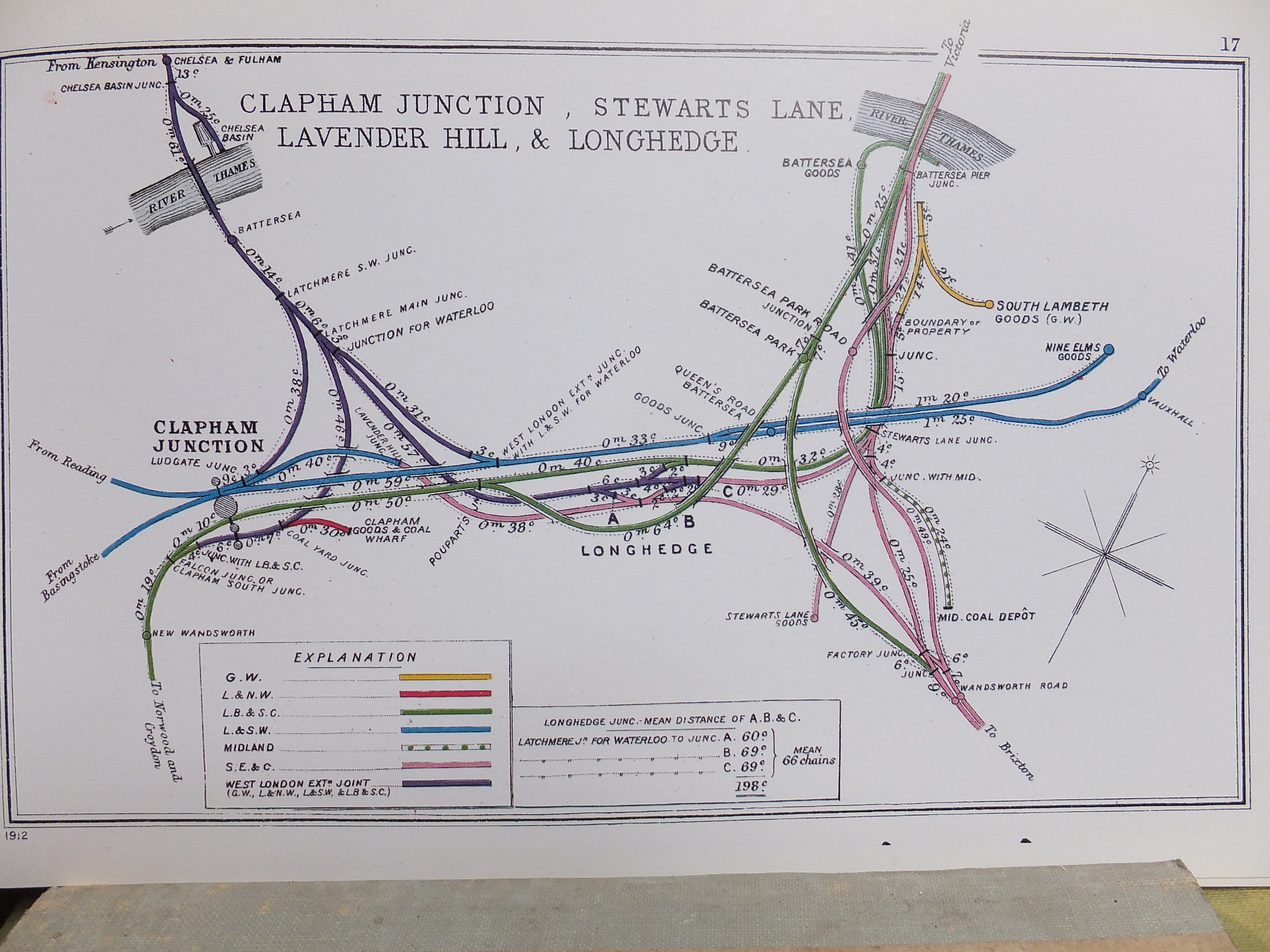
Whereas many of London's terminal stations served one railway company, Victoria ended up serving a number. The London Brighton and South Coast Railway, South Eastern Railway and the London and Chatham Railway initially terminated at London Bridge but co-operated in constructing a new route which crossed the Thames to terminate in what became Victoria Station. The London Brighton and South Coast Railway accomodated itself on the platforms on the western side. The eastern platforms were initially dual gauge and used by the Great Western Railway, the South Eastern Railway and the London and Chatham Railway. These last two railways worked together fairly closely, before amalgamating formally as the South Eastern and Chatham Railway. Traffic growth necessitated widening the Grosvenor Bridge over the River Thames to accommodate additional lines, producing a number of routes which criss-crossed one another south of the Thames, as shown in the 1914 map below.

Click for larger image.
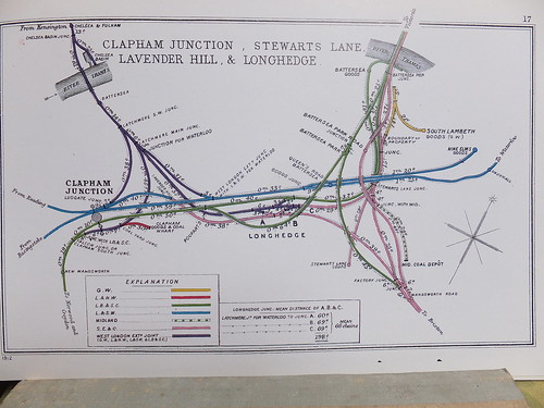
Details of the junctions between various railways in the vicinity of Victoria. This diagram is one of a series prepared by the Railway Clearing House in 1914 which appear in the reprint 'Pre-Grouping Railway Junction Diagrams 1914', published by Ian Allen (ISBN 0 7110 1256 3).

Part of the portland stone facade of the 'Chatham' side of Victoria Station (as rebuilt by the S.E.C.R. and with 'SOUTHERN RAILWAY' branding added after the 'Grouping'), viewed from the street.

Part of the 'Brighton' side of Victoria Station, viewed from the street but well-hidden by ongoing "improvements". The L.B.S.C.R. station building, built in 'Renaissance' style, is on the left with the adjacent Grosvenor Hotel, originally intended for rail travellers, on the right.

The 1921 Railways Act created the 'Big Four' (L.M.S., G.W.R., L.N.E.R. and S.R.). The Southern Railway brought together the London Brighton and South Coast Railway, the South Eastern and Chatham Railway and the London and South Western Railway. Upon Nationalisation in 1948, the Southern Region of British Railways absorbed the assets of the Southern Railway. Even today, Victoria largely operates as two stations side-by-side - the Central Section dealing with the Brighton lines and the Eastern Section serving the Chatham lines.

Signalling

The former power signal box at Victoria controlling the Central Lines. The area is now controlled from Victoria Area Signalling Control (which is actually at Clapham Junction).

Before the Victoria Area Signalling Control was brought into use at Clapham Junction in 1980, Victoria was served by two power boxes. The Eastern Section had a separate signal box with a G.R.S. power frame. This lasted until 1979 when control passed for a short time to a temporary panel in the Victoria Central power box.

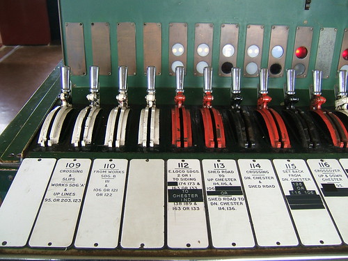
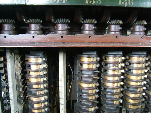
The Southern Railway had installed signalling power frames of Westinghouse Style 'K' at various locations. The Style 'K' retained mechanical interlocking between the miniature levers. The later Style 'L' 'All Electric' power frames introduced electrical interlocking between levers and the Southern Railway was an early adopter of the new design. In 1937, an order was placed for a 225-lever frame for Victoria Central with 51 point levers, 148 signal levers, 2 special levers and 24 spare levers. This was commissioned in June 1939 and continued in service until 1980. A temporary panel then took over until the new Victoria Area Signalling Control was brought into use at Clapham Junction.

A similar Style 'L' miniature lever frame in Crewe North Junction.

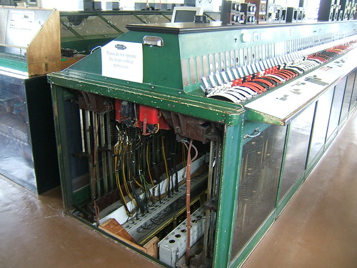
For more information about the Style 'L' frame, refer to Book Reference [3] 'The Style L Power Frame'. For more information about the Eastern Section control, click here and for the about Victoria Central control, click here. These pages are part of the splendid site 'Westinghouse Brake and Saxby Signal Co. Ltd miniature power lever frames'.

The Golden Arrow

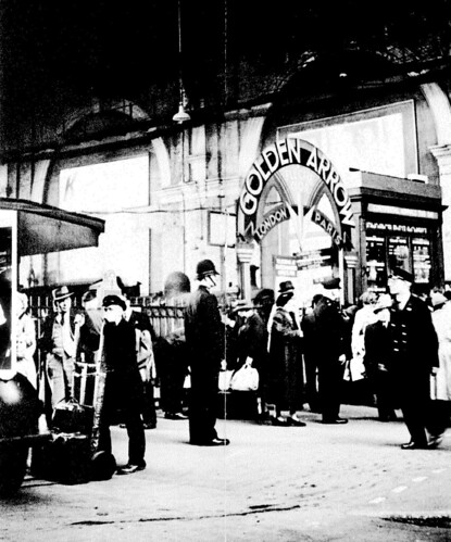
Ticket Barrier for the 'Golden Arrow' at Victoria in the 'Southern' era (Photo: VSOE).

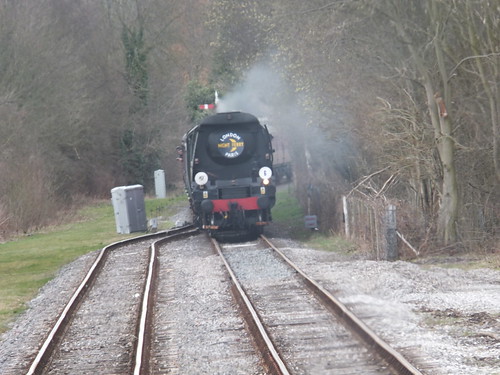
I visited Victoria in the steam era and saw the famous 'Golden Arrow' Pullman train, headed by a gleaming rebuilt Bulleid 'Pacific'. The train might have been exotic, but the station surroundings seemed very ordinary and I remember it looking very like the black-and-white picture above.

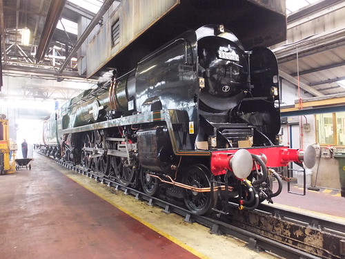
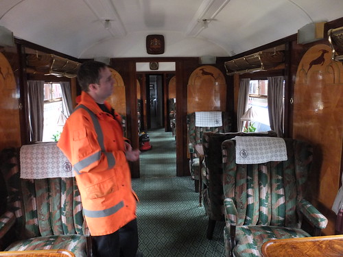
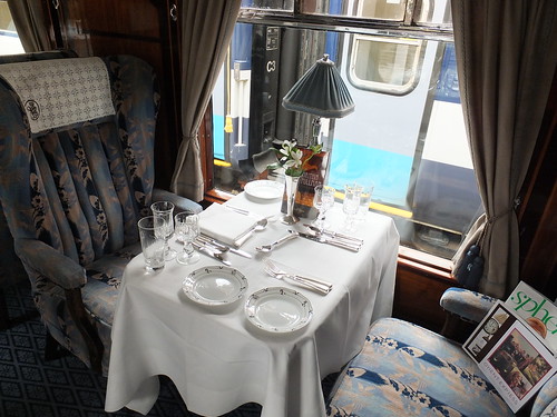
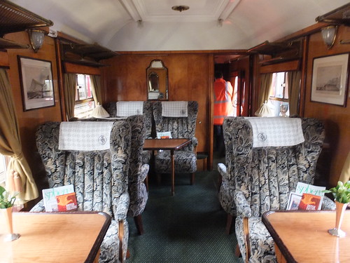
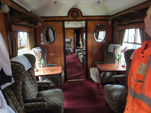
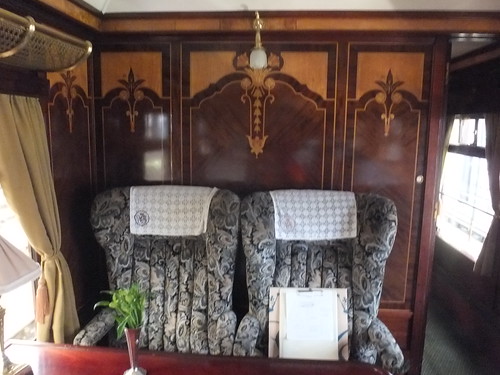
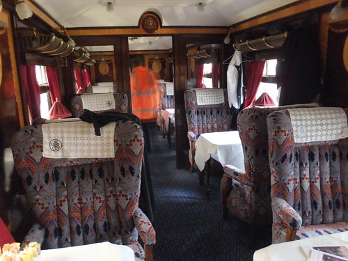
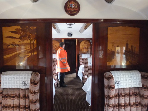
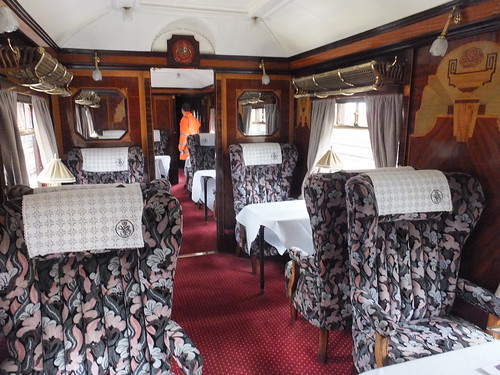
The 'Golden Arrow' is no more, but Victoria still entertains Pullman trains (sometimes steam hauled) operated by VSOE as 'The British Pullman'. I never did get to travel on the 'Golden Arrow' and (so far) I've not travelled on the 'British Pullman' but I have had a conducted tour of the 'British Pullman' rolling stock which is described here.

External web sites

London Victoria Station (Wikipedia).
Victoria (Network Rail).

External Links

London and South Western Railway (Wikipedia).
South Eastern and Chatham Railway (Wikipedia).
London, Brighton and South Coast Railway (Wikipedia).

Book References

[1] 'London's Termini' by Alan A. Jackson, published by David & Charles (0 330 02746 6).
[2] 'Railway Track Diagrams Book 5: Southern and TfL' Third Edition, published by TRACKmaps (ISBN 978-0-9549866-4-3).
[3] 'The Style L Power Frame' written and published by J. D. Francis 1989 (ISBN 0 9514636 0 8).
[4] 'History of the Southern Railway' by C. F. Dendy Marshall, revised by R. W. Kidner reprinted 1982 by Ian Allen (ISBN 0 7110 0059 X).
[5] 'Great Locomotives of the Southern Railway' by O. S. Nock, Guild Publishing, 1987 edition by Book Club Associates.
[6] 'Southern Steam' by O. S. Nock, published by David & Charles (ISBN 0 7153 5235 0).
[7] 'London's Termini' by Alan A. Jackson, published by David & Charles (0 330 02746 6).

Maps

Details of the railways around Victoria today are shown in the 'Quail Track Diagrams':-
'Railway Track Diagrams Book 5: Southern and TfL' Third Edition, published by TRACKmaps (ISBN 978-0-9549866-4-3).

My Pictures

London: Victoria.
London: former 'Southern' lines.
London's Railways.

Monday, 13 May 2013

Railway Signalling in Britain: Part 4 - Semaphore Signal Aspects by Night

At night, the arm of a semaphore signal becomes invisible so the signal aspect is given by a signal lamp (usually paraffin) in front of which two coloured filter glasses connected to the signal arm are moved:-

'Stop' signals - Display either a RED or GREEN light. 'Distant' signals - Display either a YELLOW or GREEN light.
The reliability of the lamp and its ability to continue burning in adverse weather conditions was paramount and considerable ingenuity was devoted to producing suitable designs. Care and cleanliness in the handling and maintenance of signal lamps was essential. 'Lamp Oil' was produced to a high and constant specification to ensure consistent performance. Reports of "Signal Lamp Out when should be lit" were treated with the utmost gravity.

Various designs of signal lamp, produced by different railway supply companies, were in use up to the 1960s and beyond but they had similar features, comprising a substantial sheet steel housing with a hinged lid which was permanently attached to the signal post into which a removable lamp (often called the 'vessel') could be fitted.


'ADLAKE' Lamp Housing, showing 'Bull's Eye' lens, hinging top and chimney (10p coin alongside for scale).

The front face of the housing mounted a large clear glass 'Bull's Eye' lens which focused the light through the coloured filter glasses of the signal arm.

'ADLAKE' Lamp Housing, viewed from above with hinging top opened and removable lamp assembly in position. The fillet in the back left corner of the housing ensures correct alignment of the lamp assembly.

A simple spring clip unlatched the top of the lamp housing, allowing it to hinge open for access to the removable lamp, which simply lifted out using the wire handle provided.


View of lamp removed from lamp housing. The wire carrying handle is in the 'stowed' position.

The large tank forming the base held lamp oil sufficient for 8 days continuous burning with a correctly-trimmed burner. On this pattern, all four sides of the hinging top section protecting the burner were provided with a clear glass.


'ADLAKE' Signal Lamp, opened to show burner and chimney. The locating lugs for the wick adjuster ensure correct alignment of the flame. Screw filler cap for the vessel (with retaining chain) is near front right. The sliding wire clip which latches the hinging top section closed is front right.

The burner has a metal body with a carefully-shaped porcelain insert which helps to produce a fairly broad, flat flame. A flat, woven wick is held in position in the centre of the porcelain insert, with a long 'tail' reaching down into the tank of lamp oil. The wick adjuster is turned to provide the correct length of wick projecting above the burner.

Rear view of this type of lamp housing fitted to an upper quadrant tubular post signal. The signal lamp has a clear lens at the back, the 'back light'. The cast arm at 'six o'clock' with the curved screen is the 'Back Blinder'.

At night, stop signals in advance of the box (that is, leading trains away from the box) could sometimes be seen by the controlling signalman who was able to verify the signal aspect by observation since the red or green indication was facing the signal box. But, in the case of stop signals in the rear of the box, the indication faced away from the signalman. To provide an indication of the aspect displayed at the rear of the signal, signal lamps and the lamp housing deliberately showed a white 'Backlight' at the rear. The lamp itself had a clear glass window and the lamp housing had a small clear glass 'Bull's Eye' lens which focused the light. The exact position of the 'Bull's Eye' left and right was adjustable to optimise the visibility to the signalman. The pivot for the signal arm was provided with a cast arm (at '6 o'clock in the view above) with a curved screen called the 'Back Blinder'. If the signal arm was 'On', the 'Back Blinder' did not obscure the 'Backlight' and the white light was visible to the signalman, confirming that the signal was 'On'. But, if the arm was off (or partially off) the movement of the 'Back Blinder' obscured the 'Backlight'.

Of course, not all signals could be visually checked by the signalman due to position or line curvature. Signal repeating (using electrical techniques) was developed to assist the signalman and I'll describe this in another article.


General view of a signal lamp used by the L.M.S. This was the "ADLAKE" No. 22, made by Lamp Manufacturing & Railway Supplies Ltd.

View from above showing this type of lamp housing fitted to an upper quadrant lattice post signal, with the lamp housing open to show the lighted signal lamp inside. At the top of the picture can be seen the filter glasses producing the appropriate signal aspect.

The picture above shows the red filter glass giving the 'Stop' indication. When the arm is raised to 'Proceed', the other filter glass is moved in front of the lamp. Note that the second filter glass is blue, not green. The signal oil burns with a yellow flame. When the yellow light passes through the blue filter glass, the result is a vivid green 'Proceed' indication.

High-intensity signal lighting

View other sizes.
Brereton Sidings starting signal 'off' with fixed distant for Rugeley Trent Valley below. Both signals are electrically lit and have shaped spectacle glasses, rather than the flat filter spectacle glass used with paraffin-lit signals. The disc signal mounted on the right of the post controls movements into the Power Station and has the remains of a 'secret until lit' route indicator mounted above.

Electric illumination of semaphore signals was also used for some applications. The L.M.S. adopted what they called 'High-intensity signal lighting' in a number of places where clearance or sighting limitations made the use of full-size signal arms impractical. The brighter light indications provided compensation for the poorer visibility of the miniature signal arms. The installation shown in the picture above is in conjunction with full-size arms, but on the approach to the Trent Valley Line which has colour-light signals.

My Pictures

British Railway Signalling Equipment

Go to Part 5 - Signal Arm, Slot and Lamp Repeaters.

Wednesday, 8 May 2013

Waterloo Station, London

I was brought up in the West Midlands in the early days of the post-war Nationalised railway so, although I was familiar with both the former L.M.S. and G.W.R. lines where I lived, the former Southern Railway was very much a 'foreign railway' to me. Around 1951 my mother and I visited Waterloo and other London termini during an extended trip (which even took us to Boulogne, described here). The 'Southern' electrics were very unfamiliar but there was plenty of steam to look at - particularly the 'air-smoothed' Bulleid 'Pacifics'.

A Bulleid 'Pacific' leaving Waterloo (Photo: British Railways).

It was only many years later when I started to discover some of the history of the lines in the south of the country. Waterloo was the London terminus of the London and South Western Railway, which was well-regarded for its locomotives, less so for its passenger coaches and stations. In the 20th century, the London and South Western Railway rebuilt the nondescript Waterloo, producing a terminus which was much admired. The column-free concourse and the platforms were covered by an airy glazed roof and there was an impressive array of offices on the road side of the concourse.

View across the Concourse at Waterloo in the 'Southern' era (Photo: British Railways).

I'm afraid I don't think the station has been much improved in recent years. The modern ticket barriers and retail outlets now encroach onto the platform side of the concourse which is further narrowed by the new mezzanine floor on the road side. Overhead, a bewildering array of suspended signage, CCTV cameras and loudspeakers destroys the original sense of space without easing the traveller's route through the clutter very much. Of course, it's all aimed at increasing the 'retail opportunities' offered to 'customers'.

View across the Concourse from the mezzanine adjacent to platform 1 in 2013.

Post-War developments

Upon Nationalisation of the railways in 1948, the Southern Region of British Railways absorbed the assets of the Southern Railway. The Southern Railway had been created by the 1921 Railways Act which grouped railways into the 'Big Four' (L.M.S., G.W.R., L.N.E.R. and S.R.). The Southern Railway brought together the London Brighton and South Coast Railway, the South Eastern and Chatham Railway and the London and South Western Railway. Steam working was eliminated and third-rail electrification (started by the Southern Railway in the 1930s) was extended to more destinations. Perhaps the biggest change in recent years was the building of Waterloo International to handle the 'Eurostar' trains on the Channel Tunnel route. However, once our very-first High Speed Railway was completed to St. Pancras International (briefly described here), Waterloo International was abandoned and currently wears a forlorn air as Network Rail decide just how much money will be needed to convert the area for use by other trains.

Click for larger image
A modern view of Waterloo Station (centre) with Hungerford Bridge leading to Charing Cross station towards the top. Although the station and rail approaches have been extended since first built, the way in which the line from Nine Elms was extended over arches is still apparent. The long platforms of Waterloo International (beyond the earlier train shed) served the 'Eurostar' trains until High Speed One diverted these trains to St. Pancras International.

Click for larger image
Another aerial view of Waterloo.

Origins of Waterloo Station

The London and Southampton Railway was promoted as early as 1831 and a limited service started on 21st May 1838 between a London terminus at Nine Elms and Woking Common. As construction of the line towards Southampton continued, the name of the railway was changed to the more impressive-sounding 'London and South Western Railway'. A branch to Richmond was opened in 1846 but the growing traffic showed up the inadequacy of Nine Elms as a terminus. An extension was authorised from Nine Elms to a new station near the south end of Waterloo Bridge called 'Waterloo'. In 1848, Nine Elms was closed to the public (although retained for Royal Trains and goods) when all passenger traffic was diverted to Waterloo. The initial Waterloo Station had four platforms with two 'middle lines'. The L.S.W.R. intended to extend the line beyond Waterloo to get nearer to the City of London, which was the ultimate destination for many of its regular passengers. As a stop-gap, one of the 'middle lines' was extended to form a through connection with the South Eastern Railway (later to become the S.E.C.R.) but today there's only a pedestrian connection between the terminal platforms at Waterloo and the through platforms at Waterloo East. As an alternative, the L.S.W.R. supported the initiative to build an underground electric railway from Waterloo to the City. Initially, it operated the railway on behalf of the Waterloo and City company, but it later acquired ownership. There's a little more on the Waterloo & City Line in the article here or, for a detailed history of the Waterloo and City Line, see Book [3] below.

A modern view of the imposing main entrance for foot passengers provided by the L.S.W.R. at Waterloo. After the 'Great War' of 1914-1918, this entrance became the Memorial to L.S.W.R. staff lost in World War I. The view is rather spoilt by the 'temporary' works in the foreground.

Related posts on this web site

Visiting former 'Southern' stations in London (describes Waterloo East).
Waterloo Station, London (Part 2).

External web sites

London Waterloo Station (Wikipedia).
Waterloo (Network Rail).

My Pictures

Waterloo Station.

Books

[1] 'London's Termini' by Alan A. Jackson, published by David & Charles (0 330 02746 6). (The L.S.W.R. Terminus at Waterloo is described in Chapter 11).
[2] 'Railway Track Diagrams Book 5: Southern and TfL' Third Edition, published by TRACKmaps (ISBN 978-0-9549866-4-3).
[3] 'The Waterloo & City Railway by John C. Gillham, published by the Oakwood Press (ISBN 0 85361 544 6).

[9-May 2013: Second aerial photo added, reference to Book [3] added. 18-Sep-2015: 'Related posts' added.]

Friday, 3 May 2013

Railway Signalling in Britain: Part 3 - Slotting

'Slotting' is a technique employed in semaphore signalling which gives two signal boxes control over one signal arm and was commonly used where signal boxes were close together.

Co-located Stop/Distant Signal Slotting

A frequent requirement for slotting occurred where a distant signal controlled by one signal box was mounted on the same post but below a stop signal controlled by the signal box in the rear. The 'slot' prevented the distant arm from coming 'off' until the stop signal arm above it was also 'off'.

The picture below shows the stop signal/distant signal slot on a Western Region pattern lower quadrant signal, with both signals 'on'. The weight bar nearest the camera (with two counterweights) is for the distant, the weight bar with the single counterweight is for the 'stop' signal. With no tension in the signal wires, the weightbars are held in the position shown by the counterweights. Two 'L' cranks at the bottom of the post transfer the horizontal 'pull' on the signal wires to a vertical 'pull' via two short signal wires to the ends of the two pivoted weightbars. A push-rod is attached to the stop signal weightbar, on the counterweight side of the pivot, so that, when the stop signal wire is pulled, the counterweight rises and the push rod is pushed upwards to move the signal arm to the 'off' position. A second push-rod is provided to operate the distant signal arm but this push rod is attached not to the distant weight bar, but to a third weight bar placed in between the other two. This third weight bar is provided with a smaller weight and it also has two projecting lugs which sit on top of the other two weight bars all on the other side of the pivot from the first two weightbars. With both signals 'on' the smaller weight on the third weightbar is lifted by the other two weightbars pushing up against the lugs. The weights are arranged so that if either the stop signal or distant signal wire is pulled, the remaining lug pushing up on the third weight bar keeps the smaller weight lifted.

View other sizes.
View from front of signal with neither signal wire 'pulled' - both Stop and Distant signal arms 'On'.

The picture below (taken from the other side of the signal) shows the situation if both signal wires are pulled. The tension in the stop signal wire holds the counterweight lifted and the pushrod lifted upwards to move the stop signal arm to the 'off' position. The tension in the distant signal wire holds the two distant counterweights lifted. With neither of the two weightbars pushing on the lugs of the third weightbar, the smaller weight falls under gravity, pivoting the third weightbar and lifting the distant pushrod to move the distant signal arm to the 'off' position.

View other sizes.
View from rear of signal with both signal wires 'pulled' - both Stop and Distant signal arms 'Off'.

Stop Signal Slotted by Two Signal Boxes

There were instances where it was considered unsafe for one signal box to have total control of a stop signal and co-operation between two adjacent boxes was enforced by clearing the signal only when both boxes had operated their 'slot' levers. The actual slotting mechanism at the signal was similar to that described above for Stop/Distant Signal Slotting.

Sedgeley Junction signal box had an example. If you look at the sketch signal box diagram in the post Sedgeley Junction (again) you can see that lever 35 'slotted' Dudley East's Down Starter. This was to provide protection for a train on the Down at Coneygree. This particular instance was a bit odd because the slot stood 'off' - you only pulled the lever when you wanted to ensure that Dudley East's Down Starter remained 'on' - the lever was 'normal' most of the time, giving Dudley East sole control of the signal.

The Up and Down Goods between Deepfields and Spring Vale was another example. My Deepfields signal box diagram in the post Railway signalling: Deepfields shows the slot on signal 38 (but omits the ones on 23, 28 and 29, although I did record the complexity of the stop/distant slotting on the down: to get Spring Vales's Distant signal mounted underneath the stop arm controlled by Deepfields lever 2 to show 'off', four weight bars had to be 'off' - one pulled by Spring Vale, one each pulled by Deepfields levers 2, 3 and 4). My signal box diagram of Spring Vale in the post Railway Signalling: Spring Vale Sidings Box does show the slots on Deepfields 23, 28 and 29.

Certainly in London and North Western Railway Signal Boxes, it was common to give the signalman an indication of whether the slot operated by the other box was 'off'. This was achieved by providing 'Face Disks' behind the frame, operated by signal wire. These normally sat horizontal but, when pulled vertical by the other box, displayed 'SLOT OFF'. The excellent book 'A Pictorial Record of L.N.W.R. Signalling' by Richard D. Foster, published by Oxford Publishing Company in 1982 (SBN: 86093 147 1) has more details.

Maintenance of this mechanical complexity must have been a problem and I think there was a policy of eliminating it where possible. I'm sure it's the sort of thing to appeal to A.F. Bound (the LMS Chief Signal and Telecommunications Engineer from 1929). Increasing provision of track circuits, Block Control and electric lever locks would provide justification in some instances for the elimination of mechanical slotting. Another technique was 'Distant Indicator Working' which is briefly described in section 8 of the post Railway Signalling: Tipton (Part 2) and I believe the signalmans' regulations applying where Distant Indicators were provided probably lessened the need for traditional slotting.

Go to Part 4 - Semaphore Signal Aspects by Night.

Railway Signalling in Britain: Part 2 - Semaphore Signals

Part 1 described the evolution of fixed signals. After a long period of development, the 'modern' form of 2-aspect semaphore signalling emerged (but is now being rapidly eliminated by Network Rail).

Types of Fixed Signals

There are two principal classes of fixed signal:-

'Stop' signals - these are mandatory and an approaching driver must stop if the signal displays a 'stop' aspect.

'Distant' signals - these are warning and an approaching driver may pass the signal displaying a caution or restrictive aspect but be prepared to stop at the following 'stop' signal.
Signals comprise a vertical post (of wood, steel tube, steel lattice or occasionally reinforced concrete) on which is mounted one or more 'stop' or 'distant' signal arms each comprising a rectangular 'blade' (of wood or steel) mounted on a pivot so as to extend to the left of the signal post (viewed from an approaching train to which the signal applies) at a height to facilitate observation by the driver of an approaching train.

The two types of signal arm are distinguished by day as follows:-
'Stop' signals - Arm is square-ended. Front of arm is RED with a WHITE vertical band near the end, rear is WHITE with a BLACK vertical band near the end.

View other sizes.
Upper quadrant 'Stop' signal displaying 'STOP' indication (Shackerstone Outer Home).

'Distant' signals - Arm is 'V'-ended. Front of arm is YELLOW with a BLACK chevron near the end, rear is WHITE with a BLACK chevron near the end.

View other sizes.
Darley Dale Down (fixed) Distant Signal. The black and white painting of the post indicates an 'Independent' Distant - one not co-located with a 'Stop' Signal.
The two types of signal are distinguished by night by providing a lamp (usually paraffin), in front of which two coloured filter glasses connected to the signal arm are moved:-
'Stop' signals - Display either a RED or GREEN light.
'Distant' signals - Display either a YELLOW or GREEN light.
Aspects

Both types of signal have two valid aspects, according to the position of the signal arm (which controls the colour of the lamp shown at night):-
Arm is horizontal ('ON' Aspect): 'STOP' (if a stop signal), 'Proceed with Caution' (if a distant signal).
At night, the indications are Red light: 'STOP'(if a stop signal), Yellow light: 'Proceed with Caution' (if a distant signal).
Arm is raised or lowered by 45 degrees ('OFF' Aspect): 'PROCEED'.
At night, the indications are Green light: 'PROCEED'.
If the arm is raised by 45 degrees to indicate 'PROCEED', signal is termed 'UPPER QUADRANT' or, if lowered by 45 degrees to indicate 'PROCEED', signal is termed 'LOWER QUADRANT'.

Subsidiary signals

For special purposes (such as shunting), there are various types of 'Subsidiary signal'. These are 'Stop' signals but provided with smaller arms than 'main' signals and often mounted on the same 'doll' as a main signal.

An elderly Great Western signal. The signal arms are wooden, as is the 'doll' (vertical post) mounting the arms. The lower arm is smaller and the 'S' indicates that it authorises a shunting movement past the signal.

Diverging routes

'Stop' signals are often situated in advance of turnouts (points) where two (or more) routes diverge. Railways in Britain provide 'Route Signalling' where, at diverging lines, there is a separate signal arm for each route. Originally, these arms were placed on a single post, one above the other, with the topmost arm referring to the leftmost route. Particularly where there were more than two routes, this was judged harder for an approaching driver to correctly interpret at speed so this arrangement persisted only on slower lines, such as Goods Lines.

On main lines, individual signal arms are placed on separate, secondary signal posts carried side-by-side on a bracket from a single main signal post. Where a large number of routes are to be signalled, a gantry (or 'signal bridge') carried by two or more posts or supports can be provided. On bracket signals or gantries, the secondary posts are called 'dolls'. The leftmost 'doll' applies to leftmost route and so on.

'Stepping' relates to the relative height above ground of the arms. The highest arm is the highest speed route and so on. Two routes with the same speed limit have the corresponding signal arms 'stepped' to the same height. Note that no absolute speed is implied, requiring the driver to have a detailed route knowledge. [Foreign railways (unless under British influence) developed a system of Speed Signalling where the driver didn't know what route he was to take, only a safe speed to run at. Different signal aspects implied different absolute permitted speeds. It can be argued that this means drivers do not need such detailed route knowledge].

View other sizes.
Lower quadrant Two-doll bracket 'Stop' signal at Tyseley viewed from the rear. This is a standard Western Region pattern. Each 'doll' (post) carries a main arm and a subsidiary (calling-on) arm and is topped with a 'ball and spike' finial.

Positioning of Fixed Signals

Signals are provided to allow each signalman to control trains in his area. On normal double track lines, 'STOP' signals implement the 'Block System'. Each signalman became responsible for the line on which trains approach extending from the previous signalman to his own location. This was called the 'Block Section'. Only one train is allowed in each 'block section' at a time so as to avoid collisions. Each signalman communicated with the signalmen on either side using special electric telegraph instruments called 'Block Signalling Instruments'. There's a little more about 'Block Signalling Instruments' (particularly those produced by the London and North Western Railway) here.

The first 'STOP' signal at each signal box is called the 'Home Signal'. The last 'STOP' signal at each signal box is called the 'Starting Signal' (or 'Starter'). The term 'Section Signal' is increasingly used as an alternative (since the signal controls admission of trains to the Block Section for the next signal box).

Depending upon the location, a 'Starting' signal may not be provided and the 'Home' signal may also serve as the 'Section' signal. Conversely, a signal box may control additional stop signals and there may be more than one 'Home' signal on the approach to the signal box and there may be more than one 'Starting' signal.

To give an approaching driver advance warning of the aspect showing on the 'Home' and 'Starting' signals at the next signal box, a 'Distant' signal is placed in the rear of the 'Home' signal at a distance which, if the 'Distant' is 'On', will allow the driver to bring his train to a stand at the 'Home' signal bearing in mind the maximum permitted speed, the prevailing gradient and the braking characteristics of trains using the route. This distance may be a mile or more. Interlocking of the levers in the signal box is arranged so that the 'Distant' signal can only be cleared to 'Off' if the levers for all the 'Stop'signals on the signalled route have been operated.

Where signal boxes are fairly close together, the requirement to place the 'Distant' signal at a sufficient distance from the 'Home' may result in the 'Distant' signal arm being placed on the same post (and underneath) the last 'Stop' signal of the box in the rear, as shown in the picture below. In some cases, the position of the co-located 'Stop' and 'Distant' signal arms may still not offer sufficient braking distance, in which case a 'Distant' signal arm will also be fitted below a previous 'Stop' signal.

View other sizes.
Darley Dale's Down Home Signal - a tubular post upper quadrant signal with fixed distant for the next signal box (Church Lane) mounted below. Note the Ground Disc signal and Signal Post Telephone mounted at the bottom of the post.

Signal Sighting

It's important that a driver will be able to see a signal at the earliest possible opportunity and great care is taken in the positioning of each signal. Signal posts may be short (where an overbridge before a signal limits the driver's view), tall (where it is desired to 'lift' the arm above a visually confusing background) or cantilevered left or right to improve the driver's ability to 'sight' the signal.

View other sizes.
Church Lane Down Outer Home is a single doll mounted on a right-hand bracket. The 'White Diamond' sign mounted underneath the signal arm was introduced where track circuiting indicated the position of a train detained at the signal in the signal box, relieving the Fireman of the need to report to the signal box to carry out what was originally 'Rule 55'.

Mechanical Operation of Signals by Wire

Operation of the lever in the signal box (from the 'NORMAL' position to the 'REVERSE' position) pulls a stranded steel wire which is carried on a series of pulleys to the signal location where the 'pull' is used to change the signal aspect. A counterweight at the signal ensures that, if the signal wire breaks, the signal arm is returned to the 'On' aspect. The counterweight also assists in returning the arm to 'ON' if excessive friction along the signal wire route tends to prevent the signal wire moving back to the original position when the lever in the signal box is replaced to 'NORMAL'.

View other sizes.
Single signal wire carried on a 2-way alloy signal pulley. The pulley is mounted on a vertical post driven into the ground (in this case a length of U-channel point rodding).

Where signal wires need to change direction (for instance, to cross to the other side of running lines), the change of direction is made on horizontal pulley wheels. A length of chain is interposed into the signal wire in the vicinity of the pulley to provide sufficient flexibility to accommodate 90 degree changes of direction. Depending upon the complexity of the layout, one or more pulley wheels may be fitted to a cast iron carrying frame which is fixed to a wood or concrete 'bed' set into the ground. These pulleys are normally referred to as 'Chain Wheels'.

View other sizes.
Single chain wheel providing around 90 degree change of direction to the signal wire. The frame of the chain wheel is bolted to a concrete 'bed'.

View other sizes.
A more complex run of signal wires (just to the left of the temporary fencing) at Tyseley. In this case, the pulleys are carried on flat steel spikes driven into the ground and a 4-way signal pulley is fitted back-to-back with a 3-way pulley.

There's an article on semaphore signalling on the London and North Western Railway here.

Go to Part 3 - Slotting.

Sunday, 28 April 2013

Railway Signalling in Britain: Part 1: Introduction

I've been interested in railway signalling from a fairly tender age. 'Visiting Signalboxes' talks about this interest and links to recollections of a number of signalboxes. Railway Signalling is a massive subject and I can't hope to offer a comprehensive guide but I will attempt to outline some of the principles involved in a (no doubt erratic) series of articles. This series is confined to 'Britain'. British methods were exported to many parts of the world (particularly former British Empire countries) but quite different techniques evolved elsewhere.

The 131-lever frame of Exeter West, preserved at Crewe Heritage Centre, represents the final stage of the development of mechanical signalling aided by electrical controls and track circuits for the detection of trains.

Early railways used hand signals to communicate with trains. On the Stockton and Darlington Railway, it's said that at night they placed a candle in the window if they wanted a train to stop. The problems of correctly interpreting such casual indications led to the creation of 'fixed signals'. This is a post, fixed in a given location, on which some sort of signal can be displayed, to provide a more effective method of signalling to trains. Different railways initially used an amazing variety of Fixed Signals with Disks, Square boards, Crossbars, Balls, Arms, even a 'Curtain' in a frame which could be displayed or furled away. These 'targets' could be raised, lowered, twisted on edge, pivoted or even taken away.


A crucial shortcoming of the early hand signals was that whilst various displays with arms raised were given to signal 'Caution' or 'Stop', 'All Right' was usually given by standing at 'Attention' with arms lowered. In other words, if you couldn't see arms, that meant 'All Right'. At first, fixed signals has the same weakness. For instance, a vertically-pivoted disc could be twisted on edge to be invisible to the approaching train. Thus, if a driver couldn't see a signal, he assumed it was 'All Right'.

Gradually, signals evolved into the form we recognise with a flat blade or arm extending from the post and pivotted to it, rather like the mechanical semaphores then used for telegraph purposes. The word 'semaphore' is also used to describe this class of railway signals.

But the idea of 'hiding' the arm for 'All Right' persisted in designs where the arm could be lowered until it hung down vertically in a slot in the signal post.


The idea that a signal should always give a positive indication was not fully adopted until after the Abbots Ripton accident in 1876 where a signalman attempted to place signals at 'Danger' but, with previously-lowered arms frozen in the slot, 'All Clear' continued to be displayed (There's an excellent Wikipedia article describing this accident).

Double-track railways

Back in 1830, the Liverpool & Manchester Railway adopted a 'Time Interval' system, suitable for a double-track railway where trains were only allowed to travel in one direction on each line. In Britain, double-track railways, like roads, adopted left-hand running. There were initially no 'fixed signals' but 'Railway Policeman', stationed at strategic places along the railway, would give different hand signals to an approaching train, according to the time which had elapsed since the previous train had passed. The 'Time Interval' system was a fairly rough-and-ready approach which failed to ensure that trains maintained a safe separation.

It was eventually realised that a 'Space Interval' system was required. The invention of the Electric Telegraph allowed the Block System to be developed. The 'Railway Policeman' became the 'Signalman' (although railway slang still refers to a signalman as 'Bobby' for the same reason that civil police may be called 'Bobbies' - in commemoration of the creation of the Police Force by Sir Robert Peel).

Each signalman became responsible for the line on which trains approach extending from the previous signalman to his own location. This was called the 'Block Section'. Each signalman communicated with the signalmen on either side using special electric telegraph instruments called 'Block Signalling Instruments'. There's a post with more information on the Block Signalling Instruments used by the London and North Western Railway here.

Single-track railways

Single-line railways needed a different approach as there was not only the danger of one train catching up with another but the possibility of two trains meeting head-on. Single-line control eventually benefitted from the use of electricity allowing communication from one end of a single line section to the other.

Go to Part 2 - Semaphore Signals.

Wednesday, 24 April 2013

The British Pullman

Venice Simplon Orient Express (VSOE) operate a number of exclusive luxury train services, re-creating the glamour of rail travel in the 1920s and 1930s. In Britain, they operate the 'Northern Belle' (formed from converted 'Mark 2' coaches) and the 'British Pullman' (formed from restored 'Pullman' coaches).

Many of the 'British Pullman' trains operate from London's Victoria station and VSOE have their carriage workshops nearby at Stewarts Lane. On 11th April 2013, I was shown around the workshops by Julian, the Fleet Maintenance Manager.

The site is shared with Southern and Gatwick Express and, on entering the site, the modern Carriage Servicing and Inspection shed used by the Southern and Gatwick Express trains dominates the view. Julian led me under two railway bridges to reach the former Carriage and Wagon Shed now occupied by VSOE. After looking at carriage restoration work in progress, we moved on to the adjacent building, the former Electric Locomotive Running Shed, now used as a base for preserved Bulleid 'Pacific' 35078 'Clan Line', which is a regular performer on steam-hauled 'British Pullman' trains.

35078 'Clan Line' being prepared to haul the 'British Pullman' the following day.

We then made our way to the modern Carriage Servicing and Inspection shed, where the 'British Pullman' train is normally stabled. Julian and I climbed into the Support Coach at the south end of the rake, walked the length of the train (with me taking photographs) then retraced our route to the Support Coach.

Support Coach:

The Support Coach is a Brake/Composite with the normal Guard's Compartment, seating for staff and space for comprehensive spares.

ZENA:


ZENA was built in 1928 and, after working on Ocean Liner services to Plymouth and the 'Torbay Pullman' for the Great Western, she moved to the Southern, working Southampton Boat Trains and the 'Bournemouth Belle'. After World Warr II, she variously worked on the 'Queen of Scots', the 'Yorkshire Pullman', the 'Tees-Tyne Pullman' and the 'South Wales Pullman'. In 1965 she formed part of the final 'Tees-Tyne Pullman' before being taken out of service. She was initially acquired by Terry Robinson, then sold to VSOE in 1979.

VERA:


VERA entered service as a First Class Kitchen Car on the 'Southern Belle' electric train in 1932. During World War II, she suffered serious bomb damage at Victoria Station. Following rebuilding, she joined the 'Brighton Belle' in 1947. After withdrawal, she served as a 'Garden House' before being bought by VSOE for restoration in 1985. The decorative panelling is sandalwood with a mahogany border and the marquetry features gazelles and palm trees. Substantial changes to the chassis and couplings were necessary to make this vehicle suitable for running in a locomotive-hauled train.

GWEN:


'Gwen', built in 1932 for the 'Brighton Belle', was withdrawn in 1972. After serving as a restaurant in Essex, she was displayed at the Colne Valley Railway and finally acquired by VSOE in 1988. After a long period of restoration, she joined the 'British Pullman' in 1999.

PERSEUS:


Although construction started in 1938, the war delayed completion until 1951 when 'Perseus' joined the new 'Golden Arrow' which formed part of the Festival of Britain celebrations. The car continued on the 'Golden Arrow' until the last-ever run on 30th September 1972, after which it was preserved on the North Yorkshire Moors Railway prior to being bought by VSOE in 1977. It is panelled in ash and decorated with old prints.

PHOENIX:


Built in 1927, this First Class Parlour Car was originally named 'RAINBOW'. Destroyed by fire in 1936, the chassis was stored until 1952 when it was rebuilt for service on the 'Golden Arrow' and renamed 'Phoenix'. Following withdrawal, 'Phoenix' initially became a restaurant near Lyon, France, before being bought by VSOE in 1980. Present decoration incorporates oval frames with marquetry flowers using American cherry wood.

MINERVA:


Built in 1927 and featuring delicate Edwardian-style marquetry, 'Minerva' worked various Southern Railway 'Pullman' routes before being stored during World War II. In 1947, she joined the 'Devon Belle' then, in 1951, she was refurbished (as a First Class Parlour Car with Guard's Compartment) before joining the 'Golden Arrow'. Upon withdrawal in 1961, she was preserved at the Lytham Railway Museum before being acquired by VSOE in 1981.

IBIS:


Built in 1925, 'Ibis' is the oldest car in the British Pullman. It was sold to the Wagon-Lits company and operated in Italy and France before returning to England. Following rebuilding, it operated from 1930 to 1952 on the 'Golden Arrow' then from 1952 to 1963 on the Cunard Boat Trains between London Victoria and Southampton. 'Ibis' was initially preserved at the Dart Valley Railway then at the Standard Gauge Steam Trust before being acquired by VSOE. Internal decoration includes a number of oval medallions in marquetry showing a Greek dancing girl.

AUDREY:


'Audrey' was built in 1932 as a First Class Kitchen Car for the electric 'Southern Belle'. The distinctive decor features twelve different marquetry landscapes. During World War II, 'Audrey' (along with 'Vera') suffered bomb damage at Victoria Station. She operated on the 'Brighton Belle' until 1972, when the train was withdrawn. 'Audrey' was bought by David Lowther and, in 1980, she took part in the 'Cavalcade' at Rainhill celebrating the 150th Anniversary of the opening of the Liverpool and Manchester Railway.

LUCILLE:


'Lucille' was built in 1928 as a First Class Parlour Car for the 'Queen of Scots', moving to the Southern Region in 1963 to form part of the 'Bournemouth Belle'. She was bought in 1967 by Mr. Lewis-Evans as his accomodation at the South Eastern Steam Centre in Ashford. When the Steam Centre was sold-off, VSOE acquired 'Lucille' for restoration. The interior features marquetry panels using dyed green holly wood depicting Grecian urns.

Generator Car:

The 'British Pullman' is fitted with Electric Train Heating (ETH) supplied from an engine-generator set mounted in a noise-reducing housing in the Generator Car.

My thanks go to VSOE and the Fleet Maintenance Manager for making this visit possible.

Since I wrote this post, the 'VSOE' brand has been discontinued and these services are operated by Belmond. For more details of the railway trips offered in Britain by the 'Northern Belle' and the 'British Pullman, go to the Belmond site.

My Pictures

The British Pullman.

[Updated to show operator as Belmond 28-Feb-2019]

Friday, 19 April 2013

The 'Peak Forester'

Following the success of the Steam Charter to Peak Rail operated by 'Oliver Cromwell' on the 27th May 2012, a similar tour visited Peak Rail on 14th April 2013.

The return working of the 'Peak Forester' approaching Darley Dale.

In 2013, the 'Peak Forester' was operated by unrebuilt 'Battle of Britain' Class 'Tangmere', named after RAF Tangmere. This famous RAF Station, near Chichester, played an important role during the Battle of Britain (see the Wikipedia article here).

On the day of the charter, Peak Rail ran a modified service between Rowsley and Matlock Town, with a 7-coach train top-and-tailed by a steam locomotive 'Lord Phil' at the north end and a Class 31 diesel electric locomotive at the south end. I was the driver on 'Lord Phil' and Phil was the fireman.

The passing loop at Darley Dale was used to allow the steam charter to pass the Peak Rail service. When the 'Peak Forester' arrived, the Peak Rail passenger train waited in the Up platform at Darley Dale. At Rowsley, 'Tangmere' was watered, coaled, turned and serviced. With the stock for the charter shunted to the loop, the Peak Rail service was able to use the single platform at Rowsley. To allow the 'Peak Forester' to return to Network Rail, the Peak Rail service ran Empty Coaching Stock (ECS) to Darley Dale, drew onto the single line to clear the loop points. A preserved Fire Tender with around 400 gallons of water then topped-up the saddle tank on 'Lord Phil'. The ECS was then signalled into the Down platform to await the passage of the charter. Once the charter has disappeared towards Matlock, the ECS was able to continue to Rowsley before forming the last passenger service of the day to Matlock Town and back.

My Pictures

'Peak Forester' 2013.

Crewe South Junction (1940) Signal Box

Crewe South Junction Signal Box was taken out of use in 1985 but survives in a semi-derelict form.

Crewe South Junction Signal Box controlled movements at the south end of Crewe Station from 1940 to 1985. The structure of the signal box survives in a semi-derelict form. This 'ARP' box, with a Westinghouse Style 'L' Power Frame, is the last-but-one in a series of signal boxes which have controlled the important junctions at the south end of Crewe Station.

In 1938, with the threat of war and aerial attack looming, it was decided that certain strategic signal boxes should be replaced by an 'ARP' ('Air Raid Precautions') design, better able to withstand blast damage. Accordingly, Crewe North Junction and Crewe South Junction signal boxes were rebuilt, replacing the earlier 1907 signal boxes which used the 'Crewe' All Electric System. New point machines were provided and the electrically-operated semaphore signals were replaced by colour light signals. 

Westinghouse Brake and Signal Company had been supplying the Style 'L' miniature lever frame since 1929 so it was a 'safe' choice. The L.M.S. order for Crewe South Junction (together with a second for Crewe North Junction and a third 'Standby' frame) was placed in March 1939.

The Crewe South Junction lever frame order called for 227 levers made up of 72 point levers, 127 signal levers, 8 'special' levers, 7 spare levers and 13 spare spaces. These levers were supplied as 19 off 12-way sections which were mounted in-line to form one large frame.

 
Detail showing miniature levers (picture shows a similar Style 'L' frame at Crewe North Junction. White are spare, Red are signals, Black are points. The lamps on the almost vertical panel behind the levers are repeaters).

Movement of each lever drives a vertical shaft via bevel gears. The vertical shaft carries the electrical contacts used for control and interlocking.

With covers removed, the bevel gears which drive the vertical 'drum' of contacts can be seen.

The associated relays which provided the electrical interlocking were mounted on steel shelves in a large Relay Room on the ground floor. 'Shelf' relays were used, interwired on site.

When I was young, I thought it a curious-looking box but, for me, it didn't quite have the air of mystery which Crewe North Junction possessed. I went inside Crewe South Junction once in the 1970s when my firm had started supplying telecommunication equipment to the railways but, sadly, I didn't take any pictures.

The Crewe North Junction (1940) Signal Box is briefly described here

In 1985 control of the Crewe area was transferred to Crewe Signalling Centre, built on part of the site of the famous Crewe North Shed.

References

'The Style L Power Frame' written and published by J. D. Francis 1989 (ISBN 0 9514636 0 8).

External Links

Crewe South Junction by Mark Adlington.

My Pictures

Crewe Area.